service indicator BMW X5 2013 E70 Owner's Manual
[x] Cancel search | Manufacturer: BMW, Model Year: 2013, Model line: X5, Model: BMW X5 2013 E70Pages: 345, PDF Size: 9.45 MB
Page 14 of 345
Telephone 236VolumeActivate/deactivate the voice acti‐
vation system 2517Releasing the hood 289
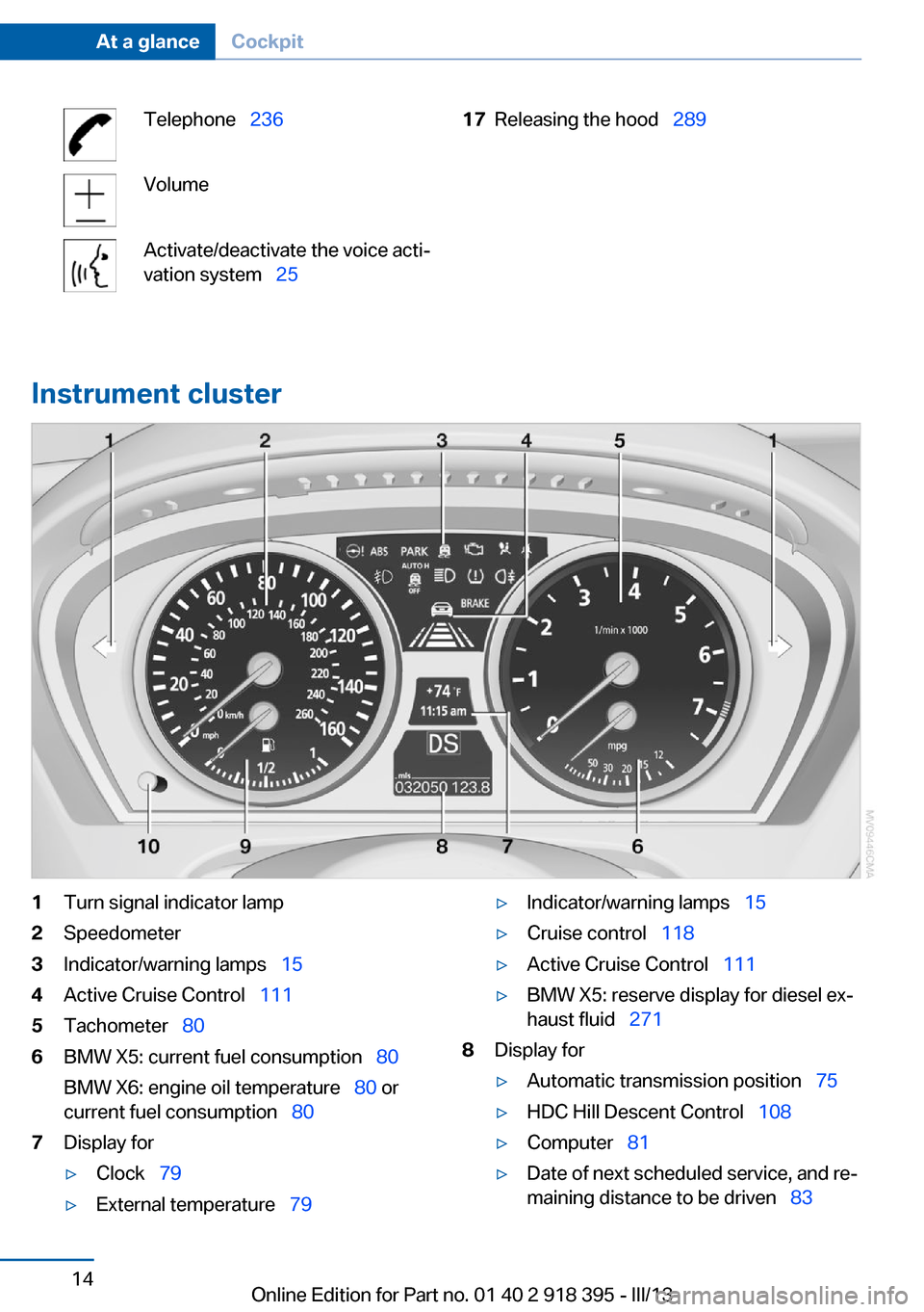
Instrument cluster
1Turn signal indicator lamp2Speedometer3Indicator/warning lamps 154Active Cruise Control 1115Tachometer 806BMW X5: current fuel consumption 80
BMW X6: engine oil temperature 80 or
current fuel consumption 807Display for▷Clock 79▷External temperature 79▷Indicator/warning lamps 15▷Cruise control 118▷Active Cruise Control 111▷BMW X5: reserve display for diesel ex‐
haust fluid 2718Display for▷Automatic transmission position 75▷HDC Hill Descent Control 108▷Computer 81▷Date of next scheduled service, and re‐
maining distance to be driven 83Seite 14At a glanceCockpit14
Online Edition for Part no. 01 40 2 918 395 - III/13
Page 15 of 345
▷Odometer and trip odometer 79▷High-beam Assistant 92▷ Check Control message
present 85▷Adaptive Drive: sport chassis and sus‐
pension tuning 1099Fuel gauge 8110Resetting the trip odometer 79
Viewing service requirement display 80Indicator/warning lamps
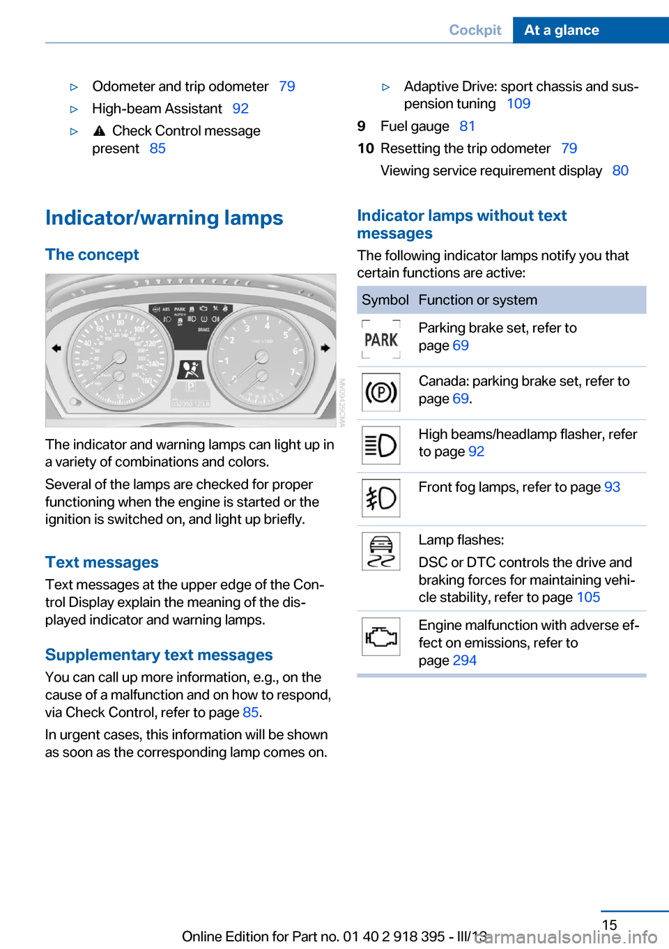
The concept
The indicator and warning lamps can light up in
a variety of combinations and colors.
Several of the lamps are checked for proper
functioning when the engine is started or the
ignition is switched on, and light up briefly.
Text messages Text messages at the upper edge of the Con‐
trol Display explain the meaning of the dis‐
played indicator and warning lamps.
Supplementary text messages
You can call up more information, e.g., on the
cause of a malfunction and on how to respond,
via Check Control, refer to page 85.
In urgent cases, this information will be shown
as soon as the corresponding lamp comes on.
Indicator lamps without text
messages
The following indicator lamps notify you that
certain functions are active:SymbolFunction or systemParking brake set, refer to
page 69Canada: parking brake set, refer to
page 69.High beams/headlamp flasher, refer
to page 92Front fog lamps, refer to page 93Lamp flashes:
DSC or DTC controls the drive and
braking forces for maintaining vehi‐
cle stability, refer to page 105Engine malfunction with adverse ef‐
fect on emissions, refer to
page 294Seite 15CockpitAt a glance15
Online Edition for Part no. 01 40 2 918 395 - III/13
Page 42 of 345
start the engine: the engine cannot be started.
The remote control is not in the vehicle or has
a malfunction. Take the remote control with
you inside the vehicle or have it checked. If
necessary, insert another remote control into
the ignition switch.
The warning lamp in the instrumentcluster lights up while the engine is
running: the remote control is no lon‐
ger inside the vehicle.
After switching off the engine, the engine can
only be started again within approx. 10 sec‐
onds if no door has been opened.
The indicator lamp in the instrument
cluster comes on and a message ap‐
pears on the Control Display: replace
the remote control battery.
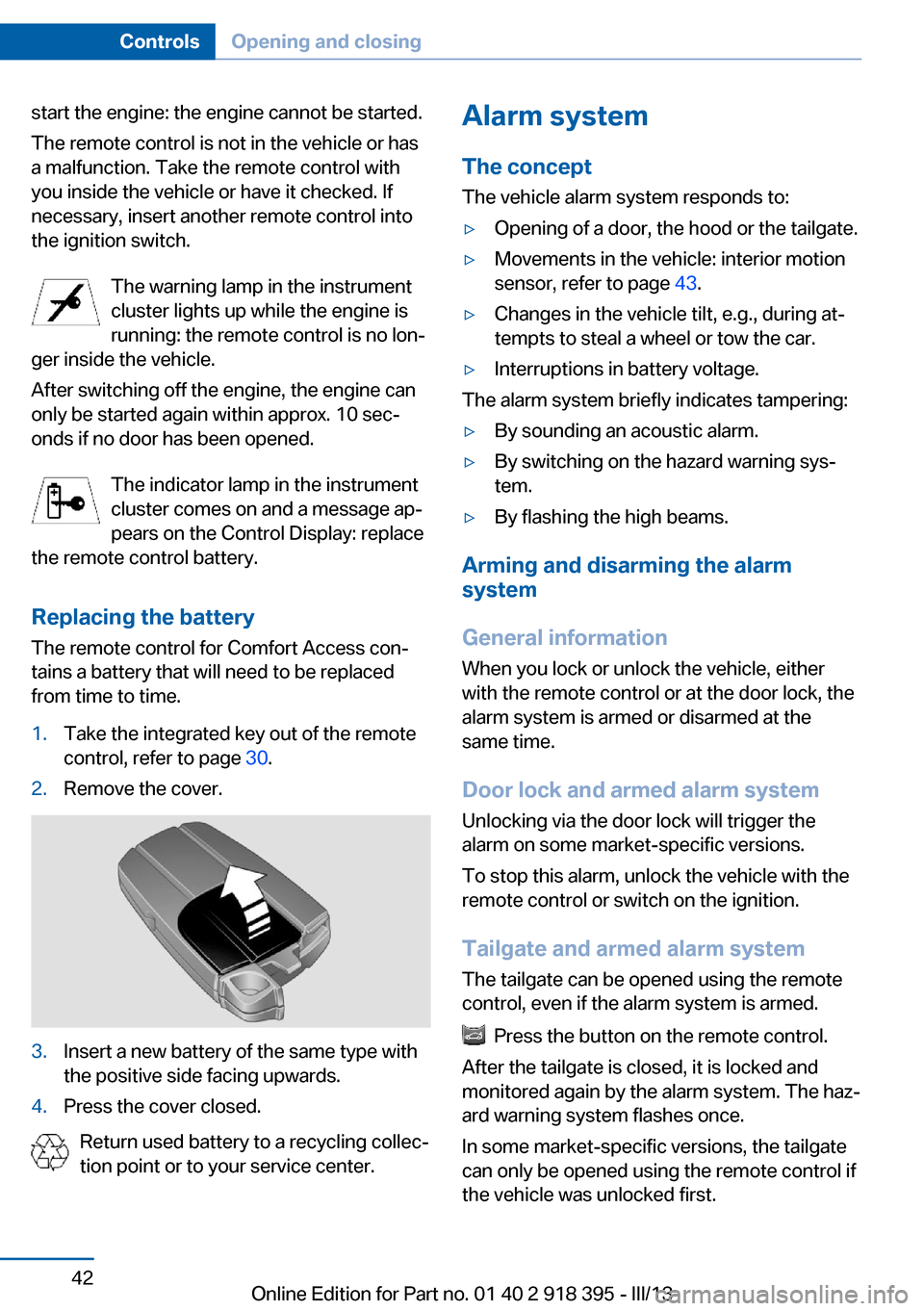
Replacing the battery
The remote control for Comfort Access con‐
tains a battery that will need to be replaced
from time to time.1.Take the integrated key out of the remote
control, refer to page 30.2.Remove the cover.3.Insert a new battery of the same type with
the positive side facing upwards.4.Press the cover closed.
Return used battery to a recycling collec‐
tion point or to your service center.
Alarm system
The conceptThe vehicle alarm system responds to:▷Opening of a door, the hood or the tailgate.▷Movements in the vehicle: interior motion
sensor, refer to page 43.▷Changes in the vehicle tilt, e.g., during at‐
tempts to steal a wheel or tow the car.▷Interruptions in battery voltage.
The alarm system briefly indicates tampering:
▷By sounding an acoustic alarm.▷By switching on the hazard warning sys‐
tem.▷By flashing the high beams.
Arming and disarming the alarm
system
General information
When you lock or unlock the vehicle, either
with the remote control or at the door lock, the
alarm system is armed or disarmed at the
same time.
Door lock and armed alarm systemUnlocking via the door lock will trigger the
alarm on some market-specific versions.
To stop this alarm, unlock the vehicle with the
remote control or switch on the ignition.
Tailgate and armed alarm system
The tailgate can be opened using the remote
control, even if the alarm system is armed.
Press the button on the remote control.
After the tailgate is closed, it is locked and
monitored again by the alarm system. The haz‐
ard warning system flashes once.
In some market-specific versions, the tailgate
can only be opened using the remote control if
the vehicle was unlocked first.
Seite 42ControlsOpening and closing42
Online Edition for Part no. 01 40 2 918 395 - III/13
Page 55 of 345
Unbuckling the belt1.Hold the belt firmly.2.Press the red button in the belt buckle.3.Guide the belt back into its reel.
The shoulder strap's anchorage point will be
correct for adult seat occupants of every build
if the seat is correctly adjusted, refer to
page 49.
The two rear safety belt buckles integrated
into the rear seat are for passengers sitting on
the left and right. The belt buckle embossed
with the word CENTER is intended exclusively
for use by passengers riding in the center posi‐
tion.
Safety belt reminder for the driver's
and front passenger seat
The indicator lamp lights up and a
signal sounds. In addition, a message
appears on the Control Display.
Check whether the safety belt has been fas‐
tened correctly.
The safety belt reminder is active at speeds
above approx. 5 mph/8 km/h. It can also be ac‐
tivated if objects are placed on the front pas‐
senger seat.
Damage to safety belts In the case of strain caused by accidents or
damage:
Have the safety belts, including the safety belt
tensioners, replaced and have the belt anchors
checked.
Checking and replacing safety belts
Have the work performed only by your
service center; otherwise, it cannot be ensured
that this safety feature will function properly.◀
Belt-force limiter
The effect of the belt-force limiter on the driv‐
er's seat is dependent on the position of the
driver's seat.
To maintain the long-term accuracy of this
function, the driver's seat must be calibrated if
a corresponding message is displayed on the
Control Display.
Calibrating driver's seat The warning lamp lights up. A mes‐
sage also appears on the Control Dis‐
play. Please calibrate the driver's
seat.1.Move the driver's seat forward until it
stops.2.Move the driver's seat forward again. It
briefly moves toward the front in the proc‐
ess.3.Set the desired seating position again.
The calibration is completed when the mes‐
sage on the Control Display disappears.
Should this message continue to be displayed,
repeat the calibration. If the message does not
disappear even after repeated calibration, have
the system checked as soon as possible.
Do not carry out calibration while the ve‐
hicle is moving
Never carry out calibration while the vehicle is
moving, as this can cause accidents.
Make sure that no persons or objects become
wedged during the calibration process, as this
can cause injuries or damage.◀
Head restraints Correctly adjusted head restraints
A correctly adjusted head restraint reduces the
risk of spinal injury in the event of an accident.
Adjusting the head restraint
Correctly adjust the head restraints of all
occupied seats; otherwise, there is an in‐
creased risk of injury in an accident.◀
Seite 55AdjustingControls55
Online Edition for Part no. 01 40 2 918 395 - III/13
Page 72 of 345
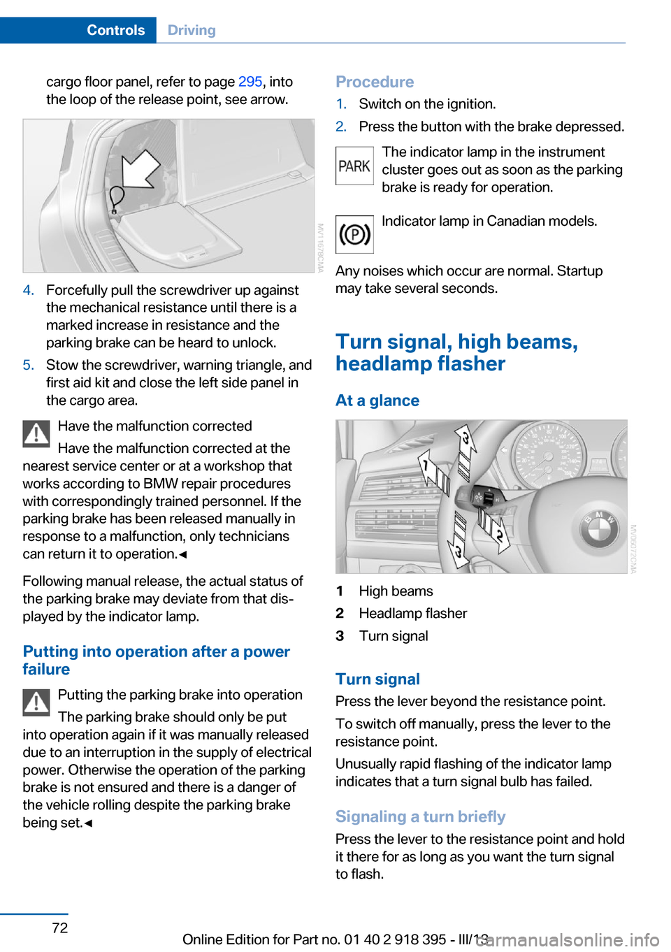
cargo floor panel, refer to page 295, into
the loop of the release point, see arrow.4.Forcefully pull the screwdriver up against
the mechanical resistance until there is a
marked increase in resistance and the
parking brake can be heard to unlock.5.Stow the screwdriver, warning triangle, and
first aid kit and close the left side panel in
the cargo area.
Have the malfunction corrected
Have the malfunction corrected at the
nearest service center or at a workshop that
works according to BMW repair procedures
with correspondingly trained personnel. If the
parking brake has been released manually in
response to a malfunction, only technicians
can return it to operation.◀
Following manual release, the actual status of
the parking brake may deviate from that dis‐
played by the indicator lamp.
Putting into operation after a power failure
Putting the parking brake into operation
The parking brake should only be put
into operation again if it was manually released
due to an interruption in the supply of electrical
power. Otherwise the operation of the parking
brake is not ensured and there is a danger of
the vehicle rolling despite the parking brake
being set.◀
Procedure1.Switch on the ignition.2.Press the button with the brake depressed.
The indicator lamp in the instrument
cluster goes out as soon as the parking
brake is ready for operation.
Indicator lamp in Canadian models.
Any noises which occur are normal. Startup
may take several seconds.
Turn signal, high beams,
headlamp flasher
At a glance
1High beams2Headlamp flasher3Turn signal
Turn signal
Press the lever beyond the resistance point.
To switch off manually, press the lever to the
resistance point.
Unusually rapid flashing of the indicator lamp
indicates that a turn signal bulb has failed.
Signaling a turn briefly
Press the lever to the resistance point and hold
it there for as long as you want the turn signal
to flash.
Seite 72ControlsDriving72
Online Edition for Part no. 01 40 2 918 395 - III/13
Page 85 of 345
Check Control
The concept The Check Control monitors vehicle functions
and alerts you to any malfunctions in the sys‐
tems monitored.
A Check Control message consists of indicator and warning lamps in the instrument cluster
and, in some circumstances, an acoustic signal
and text messages at the top of the Control
Display.
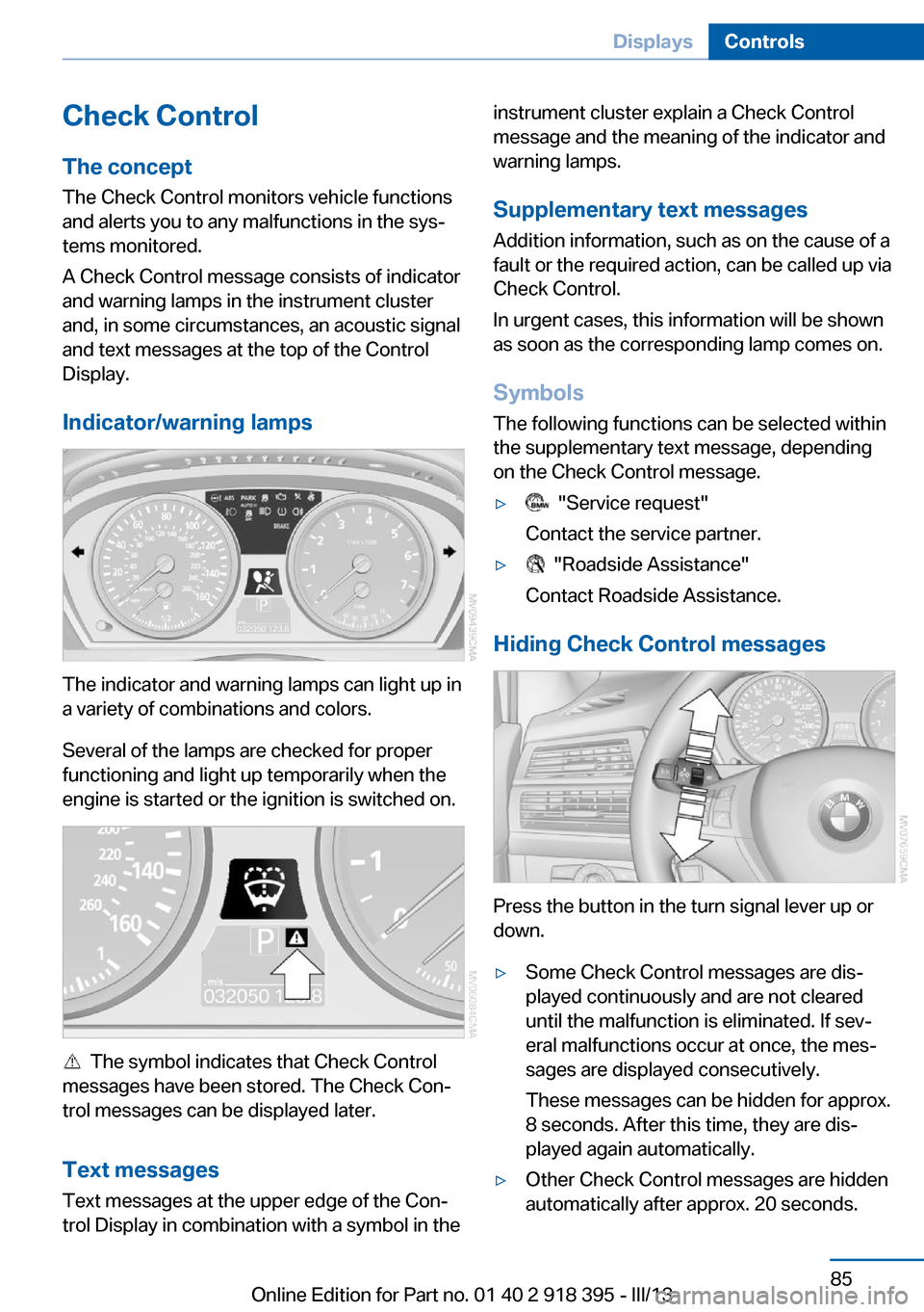
Indicator/warning lamps
The indicator and warning lamps can light up in
a variety of combinations and colors.
Several of the lamps are checked for proper
functioning and light up temporarily when the
engine is started or the ignition is switched on.
The symbol indicates that Check Control
messages have been stored. The Check Con‐
trol messages can be displayed later.
Text messages Text messages at the upper edge of the Con‐
trol Display in combination with a symbol in the
instrument cluster explain a Check Control
message and the meaning of the indicator and
warning lamps.
Supplementary text messages
Addition information, such as on the cause of a
fault or the required action, can be called up via
Check Control.
In urgent cases, this information will be shown
as soon as the corresponding lamp comes on.
Symbols
The following functions can be selected within
the supplementary text message, depending
on the Check Control message.▷ "Service request"
Contact the service partner.▷ "Roadside Assistance"
Contact Roadside Assistance.
Hiding Check Control messages
Press the button in the turn signal lever up or
down.
▷Some Check Control messages are dis‐
played continuously and are not cleared
until the malfunction is eliminated. If sev‐
eral malfunctions occur at once, the mes‐
sages are displayed consecutively.
These messages can be hidden for approx.
8 seconds. After this time, they are dis‐
played again automatically.▷Other Check Control messages are hidden
automatically after approx. 20 seconds.Seite 85DisplaysControls85
Online Edition for Part no. 01 40 2 918 395 - III/13
Page 96 of 345
▷Make sure that the front passenger is sit‐
ting correctly, i.e., keeps his or her feet and
legs in the footwell; otherwise, leg injuries
can occur if the front airbag is triggered.▷Do not place slip covers, seat cushions or
other objects on the front passenger seat
that are not approved specifically for seats
with integrated side airbags.▷Do not hang pieces of clothing, such as
jackets, over the backrests.▷Make sure that occupants keep their heads
away from the side airbag and do not rest
against the head airbag; otherwise, injuries
can occur if the airbags are triggered.▷Do not remove the airbag restraint system.▷Do not remove the steering wheel.▷Do not apply adhesive materials to the air‐
bag cover panels, cover them or modify
them in any way.▷Never modify either the individual compo‐
nents or the wiring in the airbag system.
This also applies to steering wheel covers,
the dashboard, the seats, the roof pillars
and the sides of the headliner.◀
Even when all instructions are followed closely,
injury from contact with the airbags cannot be
ruled out in certain situations.
The ignition and inflation noise may lead to
short-term and, in most cases, temporary
hearing impairment in sensitive individuals.
In the case of a malfunction, deactivation
and after triggering of the airbags
Do not touch the individual components imme‐
diately after the system has been triggered;
otherwise, there is the danger of burns.
Only have the airbags checked, repaired or dis‐
mantled and the airbag generator scrapped by
your service center or a workshop that has the
necessary authorization for handling explo‐
sives.
Non-professional attempts to service the sys‐
tem could lead to failure in an emergency or
undesired triggering of the airbag, either of
which could result in injury.◀
Warnings and information on the airbags are
also found on the sun visors.
Automatic deactivation of the frontpassenger airbags
The occupation of the seat is detected by eval‐
uating the impression on the occupied seat
surface of the front passenger seat.
The front and side airbags on the front passen‐
ger side are activated or deactivated accord‐
ingly by the system.
The indicator lamp above the interior rearview
mirror shows the current status of the front
passenger airbags, deactivated or activated,
refer to Front passenger airbag indicator lamp
below.
Leave feet in the footwell
Make sure that the front passenger
keeps his or her feet in the footwell; otherwise,
the front passenger airbags may not function
properly.◀
Child restraint fixing system in the front
passenger seat
Before transporting a child on the front pas‐
senger seat, refer to the safety notes and in‐
structions under Children on the front passen‐
ger seat, refer to page 61.◀
Malfunction of the automatic
deactivation system
When transporting older children and adults,
the front passenger airbags may be deacti‐
vated in certain sitting positions. In this case,
the indicator lamp for the front passenger air‐ bags lights up.
In this case, change the sitting position so that
the front passenger airbags are activated and
the indicator lamp goes out.Seite 96ControlsSafety96
Online Edition for Part no. 01 40 2 918 395 - III/13
Page 102 of 345
Check the tire inflation pressure and reset the
system.
Malfunction The small warning lamp flashes inyellow and then lights up continu‐
ously; the larger warning lamp comes
on in yellow. On the Control Display,
the tires are shown in gray and a message ap‐
pears. No flat tire can be detected.
Display in the following situations:▷If a wheel without TPM electronics is fitted,
for instance a compact wheel: have the
service center check it if necessary.▷Malfunction: have the system checked by
your service center.▷TPM could not be fully reset. Reset the
system again.▷Disturbance by systems or devices with
the same radio frequency: after leaving the
area of the disturbance, the system auto‐
matically becomes active again.
Declaration according to NHTSA/
FMVSS 138 Tire Pressure Monitoring
Systems
Each tire, including the spare (if provided)
should be checked monthly when cold and in‐
flated to the inflation pressure recommended
by the vehicle manufacturer on the vehicle
placard or tire inflation pressure label (If your
vehicle has tires of a different size than the size
indicated on the vehicle placard or tire inflation
pressure label, you should determine the
proper tire inflation pressure for those tires.).
As an added safety feature, your vehicle has
been equipped with a tire pressure monitoring
system (TPMS) that illuminates a low tire pres‐
sure telltale when one or more of your tires is
significantly under-inflated. Accordingly, when
the low tire pressure telltale illuminates, you
should stop and check your tires as soon as
possible, and inflate them to the proper pres‐
sure. Driving on a significantly under-inflated
tire causes the tire to overheat and can lead to
tire failure. Under-inflation also reduces fuel ef‐
ficiency and tire tread life, and may affect the
vehicle's handling and stopping ability.
Please note that the TPMS is not a substitute
for proper tire maintenance, and it is the driv‐
er's responsibility to maintain correct tire pres‐
sure, even if under-inflation has not reached
the level to trigger illumination of the TPMS
low tire pressure telltale.
Your vehicle has also been equipped with a
TPMS malfunction indicator to indicate when
the system is not operating properly. The
TPMS malfunction indicator is combined with
the low tire pressure telltale. When the system
detects a malfunction, the telltale will flash for
approximately one minute and then remain
continuously illuminated. This sequence will
continue upon subsequent vehicle startups as
long as the malfunction exists. When the mal‐
function indicator is illuminated, the system
may not be able to detect or signal low tire
pressure as intended. TPMS malfunctions may
occur for a variety of reasons, including the in‐
stallation of replacement or alternate tires or
wheels on the vehicle that prevent the TPMS
from functioning properly. Always check the
TPMS malfunction telltale after replacing one
or more tires or wheels on your vehicle to en‐
sure that the replacement or alternate tires and
wheels allow the TPMS to continue to function
properly.
Lane departure warning
The concept This system issues a warning at speeds above
approx. 40 mph/65 km/h if the vehicle is about
to leave the lane on roads with lane markings.
The steering wheel begins vibrating lightly.
The time when the warning is issued may vary
with the current driving situation.
The system does not issue a warning if the
turn signal is set before leaving the lane.Seite 102ControlsSafety102
Online Edition for Part no. 01 40 2 918 395 - III/13
Page 292 of 345
Further information on approved oil types can
be obtained from the service center.
Alternative oil types If the approved engine oils are not available, up
to 1 US quart/liter of an oil with the following
specification can be used:Gasoline engineAPI SM or a higher quality standardDiesel engineAPI ILSAC GF-5
Oil change
An oil change should be carried out by the
service center only.
Coolant
General information Danger of burns from hot engine
Do not open the cooling system while
the engine is hot; otherwise, escaping coolant
may cause burns.◀
Suitable additives
Only use suitable additives; otherwise,
engine damage may occur. The additives are
harmful to your health.◀
Coolant consists of water and additives.
Not all commercially available additives are
suitable for your vehicle. Ask your service cen‐
ter for suitable additives.
Checking the coolant level1.Do not open the hood until the engine has
cooled down.2.Turn the expansion tank cap counterclock‐
wise slightly to allow any accumulated
pressure to escape; then continue turning
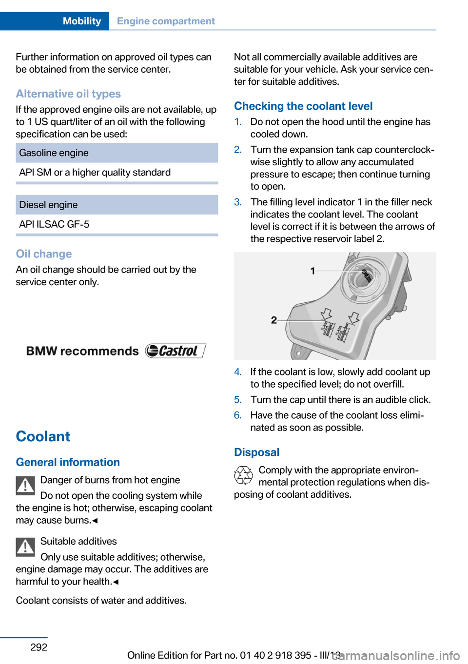
to open.3.The filling level indicator 1 in the filler neck
indicates the coolant level. The coolant
level is correct if it is between the arrows of
the respective reservoir label 2.4.If the coolant is low, slowly add coolant up
to the specified level; do not overfill.5.Turn the cap until there is an audible click.6.Have the cause of the coolant loss elimi‐
nated as soon as possible.
Disposal
Comply with the appropriate environ‐
mental protection regulations when dis‐
posing of coolant additives.
Seite 292MobilityEngine compartment292
Online Edition for Part no. 01 40 2 918 395 - III/13
Page 294 of 345
Maintenance and repair should be performed
by your service center. Make sure to have reg‐
ular maintenance procedures recorded in the
vehicle's Service and Warranty Information
Booklet for US models, and in the Warranty
and Service Guide Booklet for Canadian mod‐
els. These entries are proof of regular mainte‐
nance.
Socket for OBD Onboard
Diagnosis
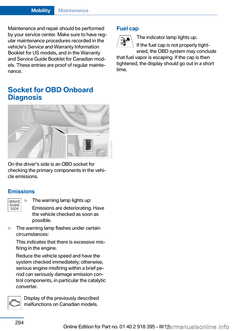
On the driver's side is an OBD socket for
checking the primary components in the vehi‐
cle emissions.
Emissions
▷The warning lamp lights up:
Emissions are deteriorating. Have
the vehicle checked as soon as
possible.▷The warning lamp flashes under certain
circumstances:
This indicates that there is excessive mis‐
firing in the engine.
Reduce the vehicle speed and have the
system checked immediately; otherwise,
serious engine misfiring within a brief pe‐
riod can seriously damage emission con‐
trol components, in particular the catalytic
converter.
Display of the previously described
malfunctions on Canadian models.
Fuel cap
The indicator lamp lights up.
If the fuel cap is not properly tight‐
ened, the OBD system may conclude
that fuel vapor is escaping. If the cap is then
tightened, the display should go out in a short
time.Seite 294MobilityMaintenance294
Online Edition for Part no. 01 40 2 918 395 - III/13