BMW X5 2014 F15 Owner's Manual
Manufacturer: BMW, Model Year: 2014, Model line: X5, Model: BMW X5 2014 F15Pages: 265, PDF Size: 6.2 MB
Page 171 of 265
▷Seat heating.
Maximum coolingPress the button.
The system is set to the lowest tem‐
perature, maximum air flow and air circulation
mode.
Air flows out of the vents for the upper body
region. Open them for this purpose.
Air is cooled as quickly as possible:
▷At an external temperature of approx.
32 ℉/0 ℃.▷When the engine is running.
Parked-car ventilation/
heating
The concept The parked-car ventilation ventilates the vehi‐
cle interior and lowers its temperature, if nec‐
essary.
The parked-car heating warms the vehicle in‐
terior, making snow and ice easier to remove.
With the ignition switched off, the air is auto‐
matically routed to the windshield, to the side
windows, and into the footwell.
The systems can be switched on and off di‐
rectly or by using two preset departure times.
The switch-on time is automatically deter‐
mined based on the temperature. The systems
promptly switch on before the selected depar‐
ture time.
Operation takes place on the iDrive or the re‐ mote control.
Hints Parked-car heating in enclosed areas
Do not operate the parked-car heating in
enclosed areas, as breathing of the harmful ex‐
haust fumes may lead to loss of consciousness
and death. The exhaust gases contain carbon
monoxide, an odorless and colorless but highly
toxic gas. Switch off the parked-car heating
when refueling.◀
Operation of the parked-car heating
When parked-car heating is in operation,
high temperatures can occur under the car
body. Before the parked-car heating is
switched on, make sure that no flammable ma‐
terials, such as hay, leaves, grass, etc. are un‐
der the vehicle. Such contact could lead to a
fire, and with it the risk of serious personal in‐
jury as well as property damage.◀
At external temperatures below 32 ℉/0 ℃, wa‐
ter vapor occurs that emerges from below the
vehicle.
Functional requirements
Parked-car ventilation▷With remote control or when the departure
time is preselected: depends on internal,
external and set temperature.▷Direct operation via iDrive: any external
temperature.▷In direct mode via remote control: external
temperature above approx. 59 ℉/15 ℃.
Open the vents to allow air to flow out.
Parked-car heating
▷With remote control or when the departure
time is preselected: depends on internal,
external and set temperature.▷Direct operation via iDrive: any external
temperature.▷In direct mode via remote control: external
temperature below approx. 59 ℉/15 ℃.▷The battery is sufficiently charged.▷The fuel tank is filled to above the reserve
range.
If the parked-car heating has not been used for
several months, it may be necessary to switch
the system on again after several minutes.
Seite 171Climate controlControls171
Online Edition for Part no. 01 40 2 926 740 - X/13
Page 172 of 265
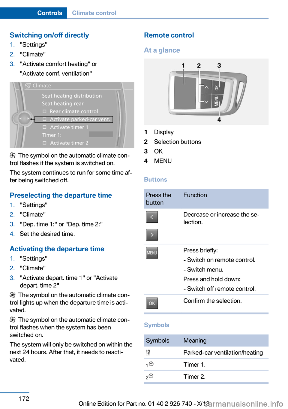
Switching on/off directly1."Settings"2."Climate"3."Activate comfort heating" or
"Activate comf. ventilation"
The symbol on the automatic climate con‐
trol flashes if the system is switched on.
The system continues to run for some time af‐
ter being switched off.
Preselecting the departure time
1."Settings"2."Climate"3."Dep. time 1:" or "Dep. time 2:"4.Set the desired time.
Activating the departure time
1."Settings"2."Climate"3."Activate depart. time 1" or "Activate
depart. time 2"
The symbol on the automatic climate con‐
trol lights up when the departure time is acti‐
vated.
The symbol on the automatic climate con‐
trol flashes when the system has been
switched on.
The system will only be switched on within the
next 24 hours. After that, it needs to reacti‐
vated.
Remote control
At a glance1Display2Selection buttons3OK4MENU
Buttons
Press the
buttonFunctionDecrease or increase the se‐
lection.Press briefly:
- Switch on remote control.
- Switch menu.
Press and hold down:
- Switch off remote control.Confirm the selection.
Symbols
SymbolsMeaning Parked-car ventilation/heating Timer 1. Timer 2.Seite 172ControlsClimate control172
Online Edition for Part no. 01 40 2 926 740 - X/13
Page 173 of 265
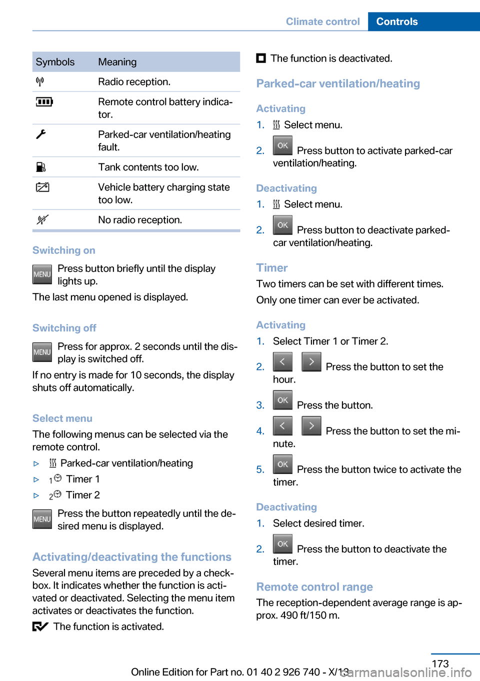
SymbolsMeaning Radio reception. Remote control battery indica‐
tor. Parked-car ventilation/heating
fault. Tank contents too low. Vehicle battery charging state
too low. No radio reception.
Switching on
Press button briefly until the display
lights up.
The last menu opened is displayed.
Switching off Press for approx. 2 seconds until the dis‐
play is switched off.
If no entry is made for 10 seconds, the display
shuts off automatically.
Select menu
The following menus can be selected via the
remote control.
▷ Parked-car ventilation/heating▷ Timer 1▷ Timer 2
Press the button repeatedly until the de‐
sired menu is displayed.
Activating/deactivating the functions Several menu items are preceded by a check‐
box. It indicates whether the function is acti‐
vated or deactivated. Selecting the menu item
activates or deactivates the function.
The function is activated.
The function is deactivated.
Parked-car ventilation/heating Activating1. Select menu.2. Press button to activate parked-car
ventilation/heating.
Deactivating
1. Select menu.2. Press button to deactivate parked-
car ventilation/heating.
Timer
Two timers can be set with different times.
Only one timer can ever be activated.
Activating
1.Select Timer 1 or Timer 2.2. Press the button to set the
hour.3. Press the button.4. Press the button to set the mi‐
nute.5. Press the button twice to activate the
timer.
Deactivating
1.Select desired timer.2. Press the button to deactivate the
timer.
Remote control range
The reception-dependent average range is ap‐
prox. 490 ft/150 m.
Seite 173Climate controlControls173
Online Edition for Part no. 01 40 2 926 740 - X/13
Page 174 of 265
The range is greatest if the remote control is
kept horizontally toward the front.
Frequencies
The remote control may not function properly
if it experiences interference from other sys‐
tems or devices that use the same frequency.
Replacing the batteries
Replace the batteries if a check control mes‐
sage is displayed or the battery indicator
flashes.
No rechargeable batteries
Do not use rechargeable batteries, as
damage may result from the substances in the
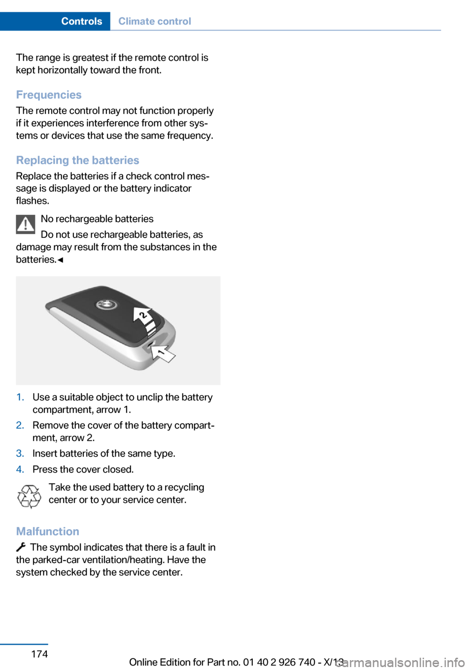
batteries.◀1.Use a suitable object to unclip the battery
compartment, arrow 1.2.Remove the cover of the battery compart‐
ment, arrow 2.3.Insert batteries of the same type.4.Press the cover closed.
Take the used battery to a recycling
center or to your service center.
Malfunction
The symbol indicates that there is a fault in
the parked-car ventilation/heating. Have the
system checked by the service center.
Seite 174ControlsClimate control174
Online Edition for Part no. 01 40 2 926 740 - X/13
Page 175 of 265
Interior equipmentVehicle equipmentAll standard, country-specific and optional
equipment that is offered in the model series is
described in this chapter. Therefore, equip‐
ment is also described that is not available in a
vehicle, e. g., because of the selected optional
equipment or country variant. This also applies
for safety-related functions and systems.
Universal garage door
opener
The concept
The universal garage door opener can operate
up to 3 functions of remote-controlled sys‐
tems such as garage door drives or lighting
systems. The universal garage door opener re‐
places up to 3 different hand-held transmitters.
To operate the remote control, the buttons on
the interior rearview mirror must be program‐
med with the desired functions. The hand-held
transmitter for the particular system is required
in order to program the remote control.
During programming
During programming and before activat‐
ing a device using the integrated universal re‐
mote control, ensure that there are no people,
animals, or objects in the range of movement
of the remote-controlled device; otherwise,
there is a risk of injury or damage.
Also follow the safety instructions of the hand-
held transmitter.◀
Before selling the vehicle, delete the stored
functions for the sake of security.
Compatibility If this symbol is printed on the packag‐
ing or in the instructions of the system
to be controlled, the system is gener‐ally compatible with the universal garage door
opener.
If you have any questions, please contact:▷Your service center.▷www.homelink.com on the Internet.
HomeLink is a registered trademark of John‐
son Controls, Inc.
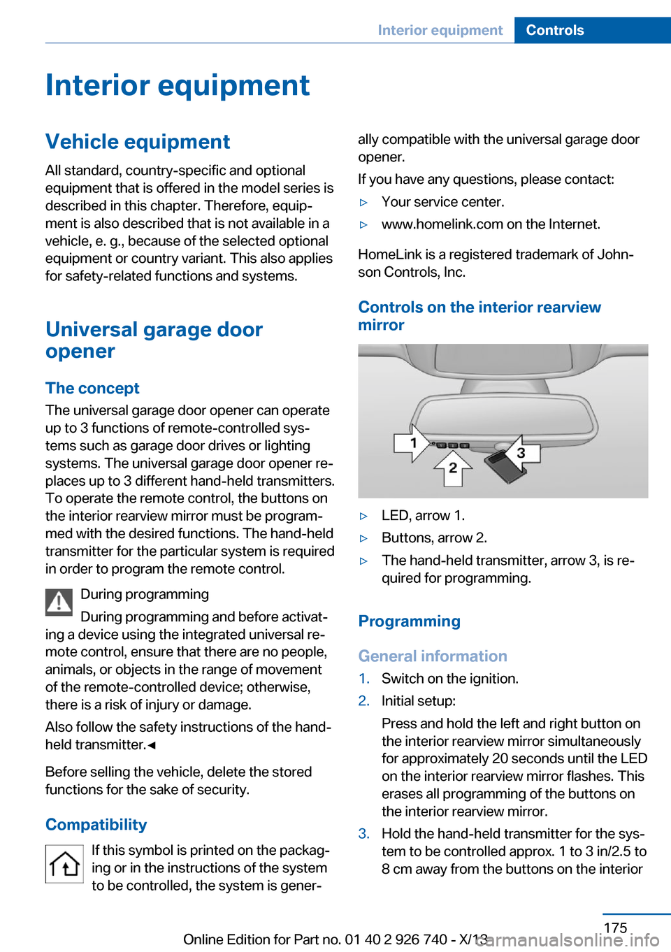
Controls on the interior rearview
mirror
▷LED, arrow 1.▷Buttons, arrow 2.▷The hand-held transmitter, arrow 3, is re‐
quired for programming.
Programming
General information
1.Switch on the ignition.2.Initial setup:
Press and hold the left and right button on
the interior rearview mirror simultaneously
for approximately 20 seconds until the LED
on the interior rearview mirror flashes. This
erases all programming of the buttons on
the interior rearview mirror.3.Hold the hand-held transmitter for the sys‐
tem to be controlled approx. 1 to 3 in/2.5 to
8 cm away from the buttons on the interiorSeite 175Interior equipmentControls175
Online Edition for Part no. 01 40 2 926 740 - X/13
Page 176 of 265
rearview mirror. The required distance de‐
pends on the manual transmitter.4.Simultaneously press and hold the button
of the desired function on the hand-held
transmitter and the button to be program‐
med on the interior rearview mirror. The
LED on the interior rearview mirror will be‐
gin flashing slowly.5.Release both buttons as soon as the LED
flashes more rapidly. When the LED is
flashing faster, this indicates that the but‐
ton on the interior rearview mirror has been
programmed.
If the LED does not flash faster after at
least 60 seconds, change the distance be‐
tween the interior rearview mirror and the
hand-held transmitter and repeat the step.
Several more attempts at different distan‐
ces may be necessary. Wait at least
15 seconds between attempts.
Canada: if programming with the hand-
held transmitter was interrupted, hold
down the interior rearview mirror button
and repeatedly press and release the
hand-held transmitter button for 2 sec‐
onds.6.To program other functions on other but‐
tons, repeat steps 3 to 5.
The systems can be controlled using the inte‐
rior rearview mirror buttons.
Special feature of the alternating-
code wireless system
If you are unable to operate the system after
repeated programming, please check if the
system to be controlled features an alternat‐
ing-code system.
Read the system's operating manual, or press
the programmed button on the interior rear‐
view mirror longer. If the LED on the interior
rearview mirror starts flashing rapidly and then
stays lit constantly for 2 seconds, the system
features an alternating-code system. Flashing
and continuous illumination of the LED will re‐
peat for approximately 20 seconds.
For systems with an alternating-code system,
the universal garage door opener and the sys‐
tem also have to be synchronized.
Please read the operating manual of the sys‐
tem being set up for information on how to
synchronize the system.
Synchronizing is easier with the aid of a sec‐
ond person.
To synchronize:1.Park the vehicle within range of the re‐
mote-controlled system.2.Program the relevant button on the interior
rearview mirror as described.3.Locate and press the synchronizing button
on the system being programmed. You
have approx. 30 seconds for the next step.4.Hold down the programmed button on the
interior rearview mirror for approximately
3 seconds and then release it. If necessary,
repeat this work step up to three times in
order to finish synchronization. Once syn‐
chronization is complete, the programmed
function will be carried out.
Reprogramming individual buttons
1.Switch on the ignition.2.Press and hold the interior rearview mirror
button to be programmed.3.As soon as the interior rearview mirror LED
starts flashing slowly, hold the hand-held
transmitter for the system to be controlled
approx. 1 to 3 in/2.5 to 8 cm away from the
buttons on the interior rearview mirror. The
required distance depends on the manual
transmitter.4.Likewise, press and hold the button of the
desired function on the hand-held trans‐
mitter.5.Release both buttons as soon as the inte‐
rior rearview mirror LED flashes more rap‐
idly. When the LED is flashing faster, thisSeite 176ControlsInterior equipment176
Online Edition for Part no. 01 40 2 926 740 - X/13
Page 177 of 265
indicates that the button on the interior
rearview mirror has been programmed.
The system can then be controlled by the
button on the interior rearview mirror.
If the LED does not flash faster after at
least 60 seconds, change the distance and
repeat the step. Several more attempts at
different distances may be necessary. Wait
at least 15 seconds between attempts.
Canada: if programming with the hand-
held transmitter was interrupted, hold
down the interior rearview mirror button
and repeatedly press and release the
hand-held transmitter button for 2 sec‐
onds.
Controls
Before operation
Before operating a system using the
integrated universal remote control, ensure
that there are no people, animals, or objects
within the range of movement of the remote- controlled system; otherwise, there is a risk of
injury or damage.
Also follow the safety instructions of the hand-
held transmitter.◀
The system, such as the garage door, can be
operated using the button on the interior rear‐
view mirror while the engine is running or when
the ignition is started. To do this, hold down
the button within receiving range of the system
until the function is activated. The interior rear‐ view mirror LED stays lit while the wireless sig‐
nal is being transmitted.
Deleting stored functions Press and hold the left and right button on the
interior rearview mirror simultaneously for ap‐
proximately 20 seconds until the LED flashes
rapidly. All stored functions are deleted. The
functions cannot be deleted individually.
Ashtray
Front
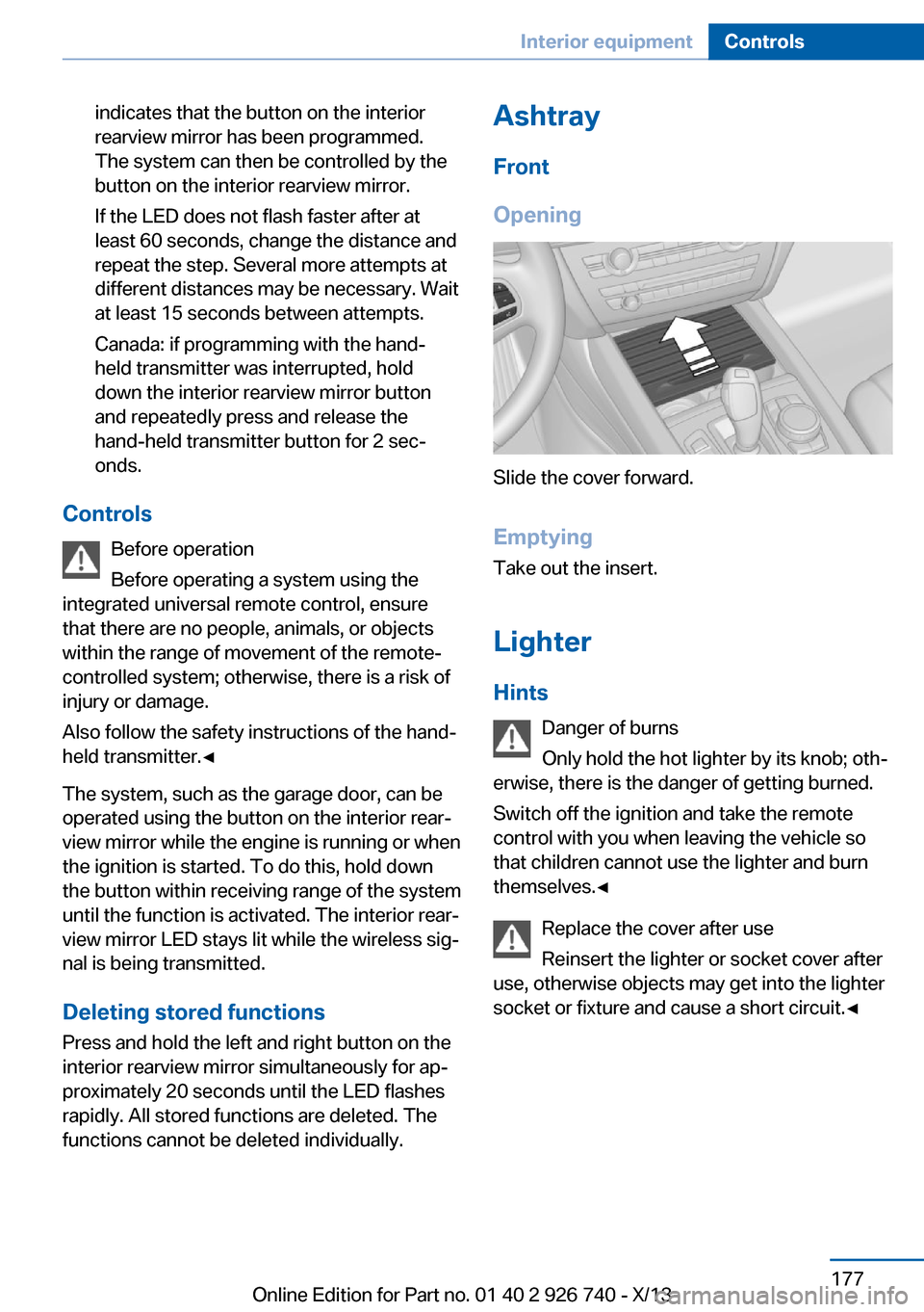
Opening
Slide the cover forward.
Emptying Take out the insert.
Lighter Hints Danger of burns
Only hold the hot lighter by its knob; oth‐
erwise, there is the danger of getting burned.
Switch off the ignition and take the remote
control with you when leaving the vehicle so
that children cannot use the lighter and burn
themselves.◀
Replace the cover after use
Reinsert the lighter or socket cover after
use, otherwise objects may get into the lighter
socket or fixture and cause a short circuit.◀
Seite 177Interior equipmentControls177
Online Edition for Part no. 01 40 2 926 740 - X/13
Page 178 of 265
Front
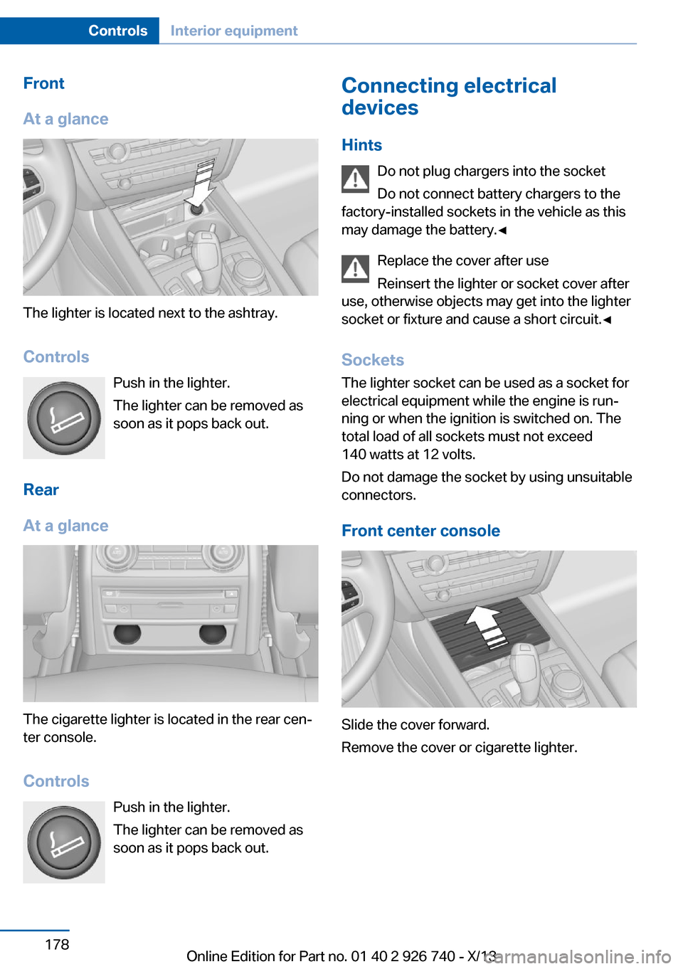
At a glance
The lighter is located next to the ashtray.
Controls Push in the lighter.
The lighter can be removed as
soon as it pops back out.
Rear
At a glance
The cigarette lighter is located in the rear cen‐
ter console.
Controls Push in the lighter.
The lighter can be removed as
soon as it pops back out.
Connecting electrical
devices
Hints Do not plug chargers into the socket
Do not connect battery chargers to the
factory-installed sockets in the vehicle as this
may damage the battery.◀
Replace the cover after use
Reinsert the lighter or socket cover after
use, otherwise objects may get into the lighter
socket or fixture and cause a short circuit.◀
Sockets
The lighter socket can be used as a socket for
electrical equipment while the engine is run‐
ning or when the ignition is switched on. The
total load of all sockets must not exceed
140 watts at 12 volts.
Do not damage the socket by using unsuitable
connectors.
Front center console
Slide the cover forward.
Remove the cover or cigarette lighter.
Seite 178ControlsInterior equipment178
Online Edition for Part no. 01 40 2 926 740 - X/13
Page 179 of 265
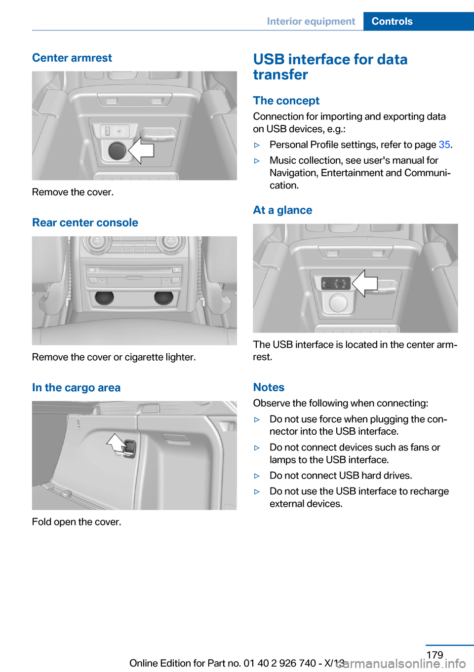
Center armrest
Remove the cover.
Rear center console
Remove the cover or cigarette lighter.
In the cargo area
Fold open the cover.
USB interface for data
transfer
The concept Connection for importing and exporting data
on USB devices, e.g.:▷Personal Profile settings, refer to page 35.▷Music collection, see user's manual for
Navigation, Entertainment and Communi‐
cation.
At a glance
The USB interface is located in the center arm‐
rest.
Notes Observe the following when connecting:
▷Do not use force when plugging the con‐
nector into the USB interface.▷Do not connect devices such as fans or
lamps to the USB interface.▷Do not connect USB hard drives.▷Do not use the USB interface to recharge
external devices.Seite 179Interior equipmentControls179
Online Edition for Part no. 01 40 2 926 740 - X/13
Page 180 of 265
Cargo area
Cargo cover
Hints Hook the cargo cover on both sides
Hook the cargo cover on both sides to
prevent damaging the cover.◀
Do not deposit heavy objects
Do not deposit heavy or hard objects on
the cargo cover. Otherwise, they may pose a risk to occupants, such as during braking and
avoidance maneuvers.◀
Do not let the trunk cover snap back into
place
Do not allow the trunk cover to snap back into
place; this can damage it.◀
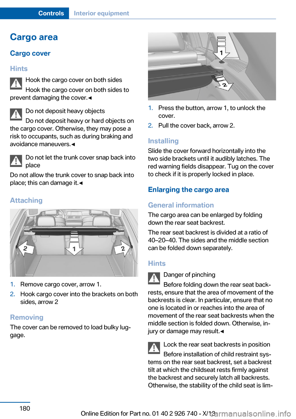
Attaching1.Remove cargo cover, arrow 1.2.Hook cargo cover into the brackets on both
sides, arrow 2
Removing
The cover can be removed to load bulky lug‐
gage.
1.Press the button, arrow 1, to unlock the
cover.2.Pull the cover back, arrow 2.
Installing
Slide the cover forward horizontally into the
two side brackets until it audibly latches. The
red warning fields disappear. Tug on the cover
to check if it is properly locked in place.
Enlarging the cargo area
General information
The cargo area can be enlarged by folding
down the rear seat backrest.
The rear seat backrest is divided at a ratio of
40–20–40. The sides and the middle section
can be folded down separately.
Hints Danger of pinching
Before folding down the rear seat back‐
rests, ensure that the area of movement of the backrests is clear. In particular, ensure that no
one is located in or reaches into the area of
movement of the rear seat backrests when the
middle section is folded down. Otherwise, in‐
jury or damage may result.◀
Lock the rear seat backrests in position
Before installation of child restraint sys‐
tems on the rear seat backrest, set a backrest
tilt at which the childseat rests firmly against
the backrest and securely latch all backrests.
Otherwise, the stability of the child seat is lim‐
Seite 180ControlsInterior equipment180
Online Edition for Part no. 01 40 2 926 740 - X/13