locking BMW X5 2014 F15 User Guide
[x] Cancel search | Manufacturer: BMW, Model Year: 2014, Model line: X5, Model: BMW X5 2014 F15Pages: 265, PDF Size: 6.2 MB
Page 56 of 265
To protect the occupants, the belt locking trig‐
gers early. Slowly guide the belt out of the
holder when applying it.
Although airbags enhance safety by providing
added protection, they are not a substitute for
safety belts.▷The shoulder strap's anchorage point will
be correct for adult seat occupants of ev‐
ery build if the seat is correctly adjusted.▷The two outer safety belt buckles,
integrated into the 2nd row of seats, are for
passengers sitting on the left and right.▷The center belt buckle of the 2nd row of
seats is solely intended for the center pas‐
senger.▷The safety belt buckles, integrated into the
3rd row of seats, are for passengers sitting
on the left and right.
One person per safety belt
Never allow more than one person to
wear a single safety belt. Never allow infants or
small children to ride on a passenger's lap.◀
Putting on the belt
Lay the belt, without twisting, snugly
across the lap and shoulders, as close to the
body as possible. Make sure that the belt lies
low around the hips in the lap area and does
not press on the abdomen. Otherwise, the belt
can slip over the hips in the lap area in a frontal
impact and injure the abdomen.
The safety belt must not lie across the neck,
rub on sharp edges, be routed over breakable
objects, or be pinched.◀
Reduction of restraining effect
Avoid wearing bulky clothing, and pull
the shoulder belt periodically to readjust the
tension. Make sure that the belt is not jammed;
otherwise, the belt can be damaged and the
restraining effect reduced.◀
Buckling the belt
Make sure you hear the latch plate engage in
the belt buckle.
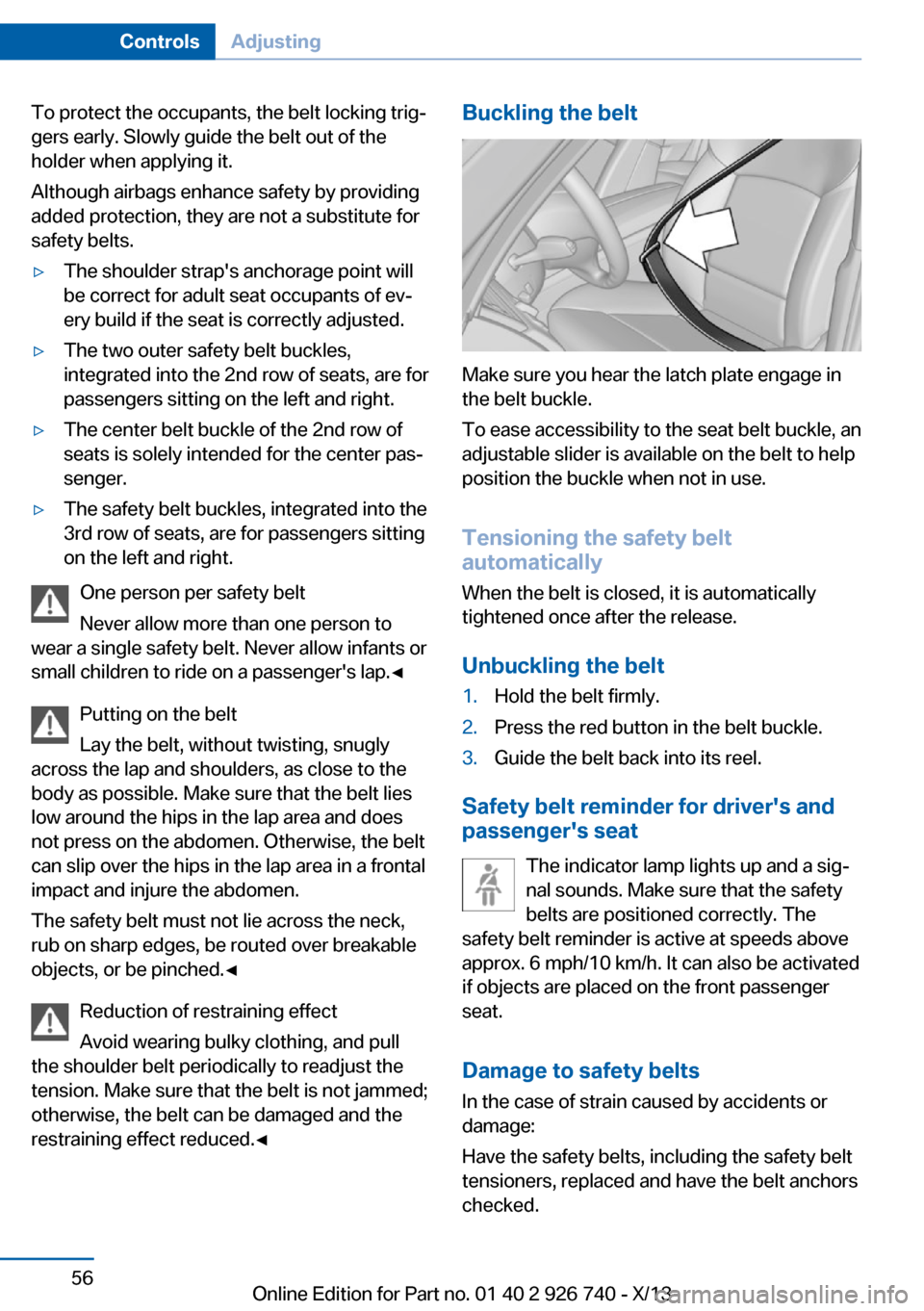
To ease accessibility to the seat belt buckle, an
adjustable slider is available on the belt to help
position the buckle when not in use.
Tensioning the safety belt
automatically
When the belt is closed, it is automatically
tightened once after the release.
Unbuckling the belt
1.Hold the belt firmly.2.Press the red button in the belt buckle.3.Guide the belt back into its reel.
Safety belt reminder for driver's and
passenger's seat
The indicator lamp lights up and a sig‐
nal sounds. Make sure that the safety
belts are positioned correctly. The
safety belt reminder is active at speeds above
approx. 6 mph/10 km/h. It can also be activated
if objects are placed on the front passenger
seat.
Damage to safety belts In the case of strain caused by accidents or
damage:
Have the safety belts, including the safety belt
tensioners, replaced and have the belt anchors
checked.
Seite 56ControlsAdjusting56
Online Edition for Part no. 01 40 2 926 740 - X/13
Page 64 of 265
Lock the rear seat backrests in position
Before installation of child restraint sys‐
tems on the rear seat backrest, set a backrest
tilt at which the childseat rests firmly against
the backrest and securely latch all backrests.
Otherwise, the stability of the child seat is lim‐
ited, and there is an increased risk of injury be‐
cause of unexpected movement of the rear
seat backrest.◀
Lock seats of the second row of seats
When equipped with a third row of seats:
when a child restraint system is installed on
the second row of seats, make sure that this
seat is correctly locked; otherwise, there is an
increased risk of injury for the child in the event
of an accident.◀
Only approved child restraint systems on
the third row of seats
On the third row of seats install only approved
child restraint systems; otherwise the protec‐
tive effect is not guaranteed and there is an in‐
creased risk of injury for the child in the event
of an accident.◀
On the front passenger seat
Deactivating airbags
After installing a child restraint fixing system in
the front passenger seat, make sure that the
front, knee and side airbags on the front pas‐
senger side are deactivated.
Deactivate the front passenger airbags auto‐
matically, refer to page 106.
Deactivating the front passenger airbags
If a child restraint fixing system is used in
the front passenger seat, the front passenger
airbags must be deactivated; otherwise, there
is an increased risk of injury to the child when
the airbags are triggered, even with a child re‐
straint fixing system.◀Seat position and height
Before installing a child restraint fixing system,
move the front passenger seat as far back as
possible and adjust its height to the highest
position to obtain the best possible position for
the belt and to offer optimal protection in the
event of an accident.
Do not change the seat position and height af‐
ter this.
Backrest width Adjustable backrest width: before installing a
child restraint fixing system in the front pas‐
senger seat, open the backrest width com‐
pletely. Do not change the backrest width
again and do not call up a memory position.
Backrest width for the child seat
Before installing a child restraint fixing
system in the front passenger seat, the back‐
rest width must be opened completely. Do not
change the adjustment after this; otherwise,
the stability of the child seat will be reduced.◀
Child seat security
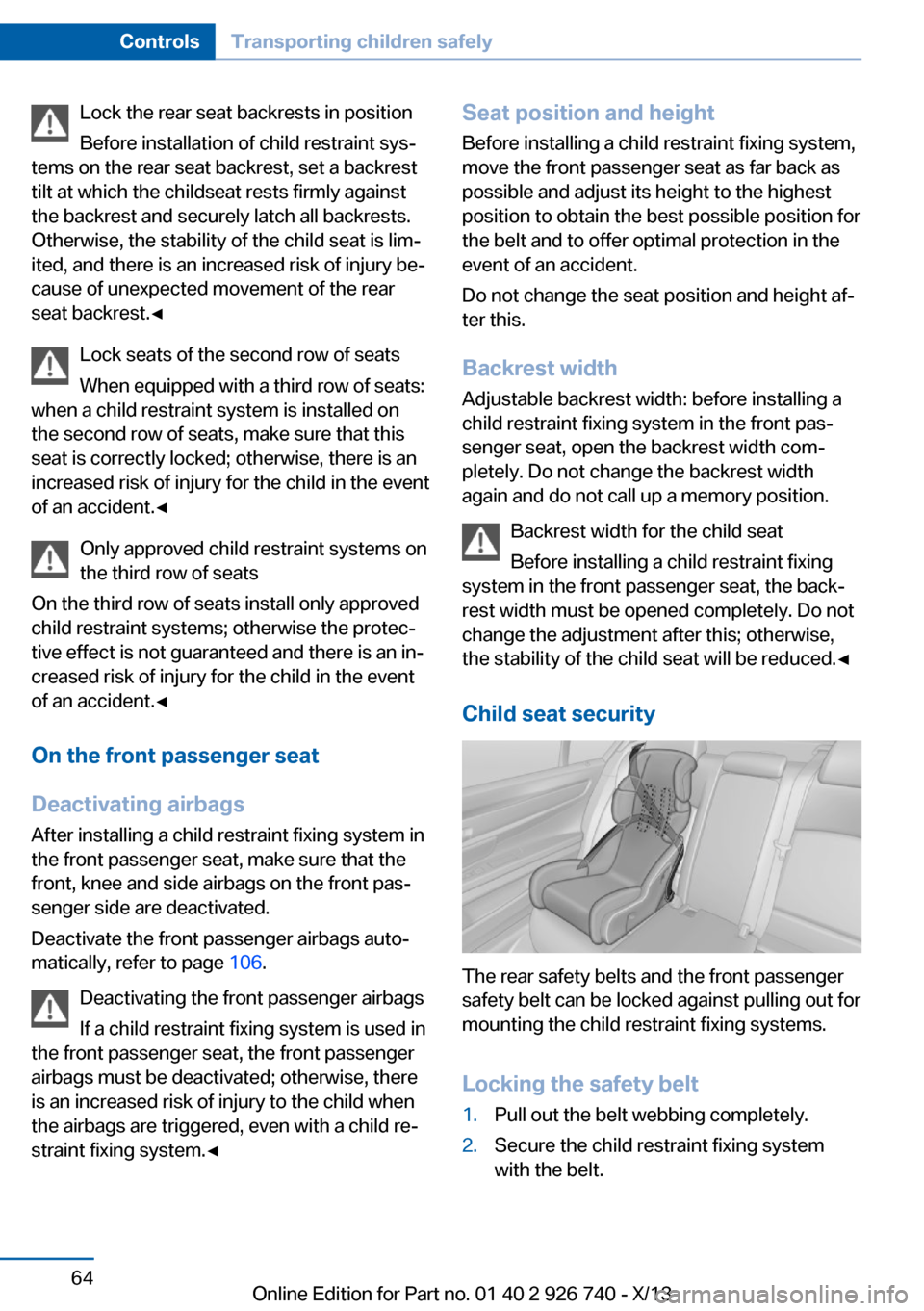
The rear safety belts and the front passenger
safety belt can be locked against pulling out for
mounting the child restraint fixing systems.
Locking the safety belt
1.Pull out the belt webbing completely.2.Secure the child restraint fixing system
with the belt.Seite 64ControlsTransporting children safely64
Online Edition for Part no. 01 40 2 926 740 - X/13
Page 65 of 265
3.Allow the belt webbing to be pulled in and
pull it taut against the child restraint fixing
system. The safety belt is locked.
Unlocking the safety belt
1.Unbuckle the belt buckle.2.Remove the child restraint fixing system.3.Allow the belt webbing to be pulled in com‐
pletely.
LATCH child restraint fixing
system
LATCH: Lower Anchors and Tether for CHil‐dren.
Note Manufacturer's information for LATCH
child restraint fixing systems
To mount and use the LATCH child restraint
fixing systems, observe the operating and
safety information from the system manufac‐
turer; otherwise, the level of protection may be
reduced.◀
Mounts for the lower LATCH anchors The lower anchors may be used to attach the
CRS to the vehicle seat up to a combined child
and CRS weight of 65 lb/30 kg when the child
is restrained by the internal harnesses.
Correctly engage the lower LATCH an‐
chors
Make sure that the lower LATCH anchors have
properly engaged and that the child restraint
fixing system is resting snugly against the
backrest; otherwise, the degree of protection
offered may be reduced.◀
Before mounting the LATCH child restraint fix‐
ing system, pull the belt away from the child
restraint fixing system.
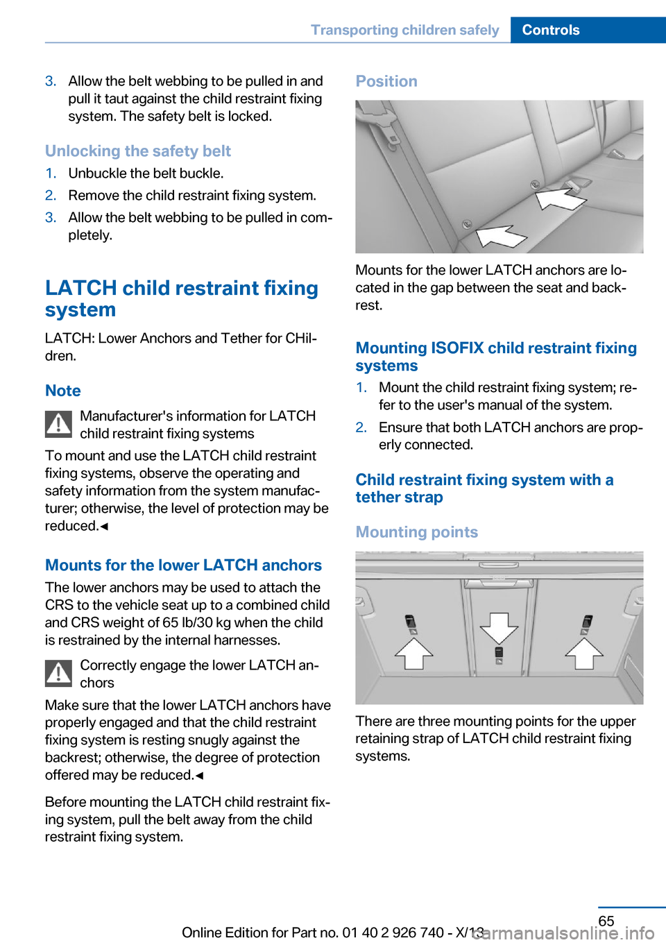
Position
Mounts for the lower LATCH anchors are lo‐
cated in the gap between the seat and back‐
rest.
Mounting ISOFIX child restraint fixing systems
1.Mount the child restraint fixing system; re‐
fer to the user's manual of the system.2.Ensure that both LATCH anchors are prop‐
erly connected.
Child restraint fixing system with a
tether strap
Mounting points
There are three mounting points for the upper
retaining strap of LATCH child restraint fixing
systems.
Seite 65Transporting children safelyControls65
Online Edition for Part no. 01 40 2 926 740 - X/13
Page 66 of 265
Note
Mounting eyes
Only use the mounting eyes for the up‐
per retaining strap to secure child restraint fix‐
ing systems; otherwise, the mounting eyes
could be damaged.◀
Retaining strap guide
Retaining strap
Make sure that the upper retaining strap
is not routed over the head restraints or sharp
edges and is free of twisting on its way to the
upper mounting point; otherwise, the belt can‐
not properly secure the child restraint fixing
system in an accident.◀
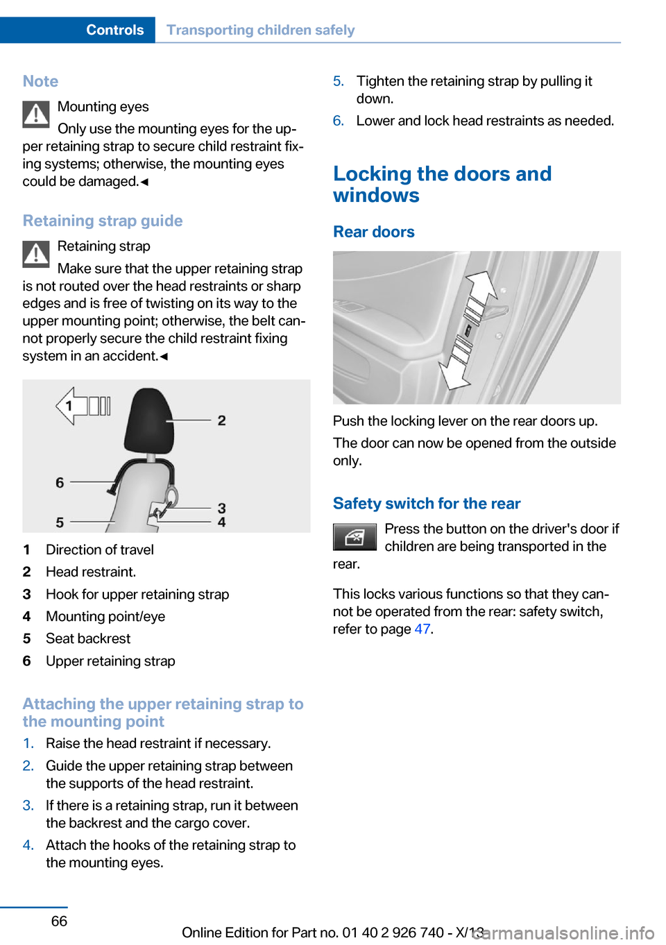
1Direction of travel2Head restraint.3Hook for upper retaining strap4Mounting point/eye5Seat backrest6Upper retaining strap
Attaching the upper retaining strap to
the mounting point
1.Raise the head restraint if necessary.2.Guide the upper retaining strap between
the supports of the head restraint.
3.If there is a retaining strap, run it between
the backrest and the cargo cover.
4.Attach the hooks of the retaining strap to
the mounting eyes.
5.Tighten the retaining strap by pulling it
down.
6.Lower and lock head restraints as needed.
Locking the doors and
windows
Rear doors
Push the locking lever on the rear doors up.
The door can now be opened from the outside
only.
Safety switch for the rear
Press the button on the driver's door if
children are being transported in the
rear.
This locks various functions so that they can‐
not be operated from the rear: safety switch,
refer to page 47.
Seite 66ControlsTransporting children safely66
Online Edition for Part no. 01 40 2 926 740 - X/13
Page 67 of 265
DrivingVehicle equipment
All standard, country-specific and optional
equipment that is offered in the model series is
described in this chapter. Therefore, equip‐
ment is also described that is not available in a
vehicle, e. g., because of the selected optional
equipment or country variant. This also applies
for safety-related functions and systems.
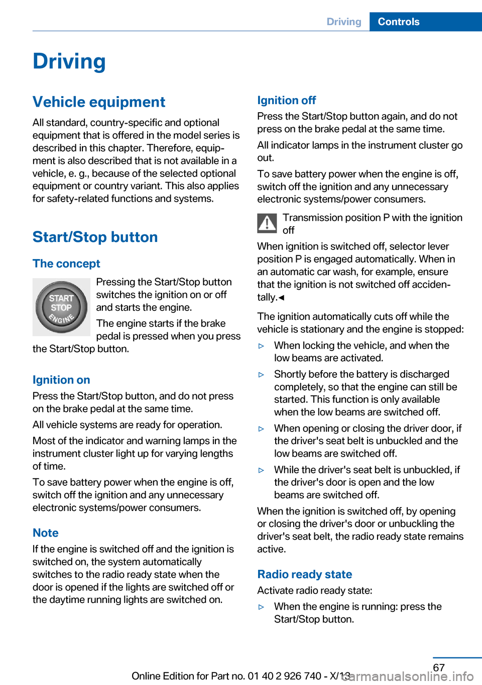
Start/Stop button The concept Pressing the Start/Stop button
switches the ignition on or off
and starts the engine.
The engine starts if the brake
pedal is pressed when you press
the Start/Stop button.
Ignition onPress the Start/Stop button, and do not press
on the brake pedal at the same time.
All vehicle systems are ready for operation.
Most of the indicator and warning lamps in the
instrument cluster light up for varying lengths
of time.
To save battery power when the engine is off,
switch off the ignition and any unnecessary
electronic systems/power consumers.
Note If the engine is switched off and the ignition is
switched on, the system automatically
switches to the radio ready state when the
door is opened if the lights are switched off or
the daytime running lights are switched on.Ignition off
Press the Start/Stop button again, and do not
press on the brake pedal at the same time.
All indicator lamps in the instrument cluster go
out.
To save battery power when the engine is off,
switch off the ignition and any unnecessary
electronic systems/power consumers.
Transmission position P with the ignition
off
When ignition is switched off, selector lever
position P is engaged automatically. When in
an automatic car wash, for example, ensure
that the ignition is not switched off acciden‐
tally.◀
The ignition automatically cuts off while the
vehicle is stationary and the engine is stopped:▷When locking the vehicle, and when the
low beams are activated.▷Shortly before the battery is discharged
completely, so that the engine can still be
started. This function is only available
when the low beams are switched off.▷When opening or closing the driver door, if
the driver's seat belt is unbuckled and the
low beams are switched off.▷While the driver's seat belt is unbuckled, if
the driver's door is open and the low
beams are switched off.
When the ignition is switched off, by opening
or closing the driver's door or unbuckling the
driver's seat belt, the radio ready state remains
active.
Radio ready state
Activate radio ready state:
▷When the engine is running: press the
Start/Stop button.Seite 67DrivingControls67
Online Edition for Part no. 01 40 2 926 740 - X/13
Page 68 of 265
Some electronic systems/power consumers
remain ready for operation.
The radio ready state switches off automati‐
cally:▷After approx. 8 minutes.▷When the vehicle is locked using the cen‐
tral locking system.▷Shortly before the battery is discharged
completely, so that the engine can still be
started.
Starting the engine
Hints Enclosed areas
Do not let the engine run in enclosed
areas, since breathing in exhaust fumes may
lead to loss of consciousness and death. The
exhaust gases contain carbon monoxide, an
odorless and colorless, but highly toxic gas.◀
Unattended vehicle
Do not leave the vehicle unattended with
the engine running; doing so poses a risk of
danger.
Before leaving the vehicle with the engine run‐
ning, set the parking brake and place the trans‐
mission in selector lever position P or neutral
to prevent the vehicle from moving.◀
Repeated starting in quick succession
Avoid repeated unsuccessful attempts to
start the vehicle or starting the vehicle several
times in quick succession. Otherwise, the fuel
is not burned or is inadequately burned, posing
a risk of overheating and damage to the cata‐
lytic converter.◀
Do not wait for the engine to warm-up while
the vehicle remains stationary. Start driving at
moderate engine speeds.
Diesel engine
If the engine is cold and temperatures are be‐
low approx. 32 ℉/0 ℃, the start process may
be delayed somewhat due to automatic pre‐
heating.
A Check Control message is displayed.
Automatic transmission
Starting the engine1.Depress the brake pedal.2.Press the Start/Stop button.
The ignition is activated automatically for a
certain time and is stopped as soon as the en‐
gine starts.
Engine stop
Hints Take the remote control with you
Take the remote control with you when
leaving the vehicle so that children, for exam‐
ple, cannot start the engine.◀
Set the parking brake and further secure
the vehicle as required
Set the parking brake firmly when parking; oth‐
erwise, the vehicle could roll. On steep upward
and downward inclines, further secure the ve‐
hicle, for example, by turning the steering
wheel in the direction of the curb. ◀
Before driving into a car wash In order for the vehicle to be able to roll into a
car wash, pay attention to the information re‐
garding Washing in automatic car washes, re‐
fer to page 244.
Seite 68ControlsDriving68
Online Edition for Part no. 01 40 2 926 740 - X/13
Page 73 of 265
DrivingAutomatic Hold is activated: the vehicle is au‐
tomatically secured against rolling after brak‐
ing to a standstill.
The indicator lamp lights up green.
Step on the accelerator pedal to drive
off.
The brake is released automatically.
The indicator lamp goes out.
Lower lamp: indicator lamp in Canadian mod‐
els
Before driving into a car wash
Before driving into the car wash, deacti‐
vate Automatic Hold; otherwise, the parking
brake will be set when the vehicle is stationary
and the vehicle will no longer be able to roll.◀
Parking The parking brake is automatically set if the
engine is switched off while the vehicle is be‐
ing held by Automatic Hold.
The indicator lamp changes from green
to red.
The parking brake is not set if the en‐
gine is switched off while the vehicle is coasting to a halt. Automatic Hold is
deactivated.
Lower lamp: indicator lamp in Canadian mod‐
els
Automatic Hold remains activated during the
engine stop brought about by the Auto Start/
Stop function.
Take the remote control with you
Take the remote control with you when
leaving the vehicle so that children, for exam‐
ple, cannot release the parking brake.◀
Malfunction
In the event of a failure or malfunction of the
parking brake, secure the vehicle against roll‐ing using a wheel chock, for example, when
leaving it.
Manual release
The parking brake can be released manually in
the event of a power failure or electrical fault.
Before releasing, secure the vehicle
against rolling
Before releasing the parking brake manually,
and whenever you park the vehicle with the
parking brake released, ensure that position P
of the automatic transmission is engaged.
Secure the vehicle in a manner appropriate to
the inclination of the road, e.g., with a wheel
chock; otherwise, there is the danger of an ac‐
cident and injuries if the vehicle rolls uninten‐
tionally.◀
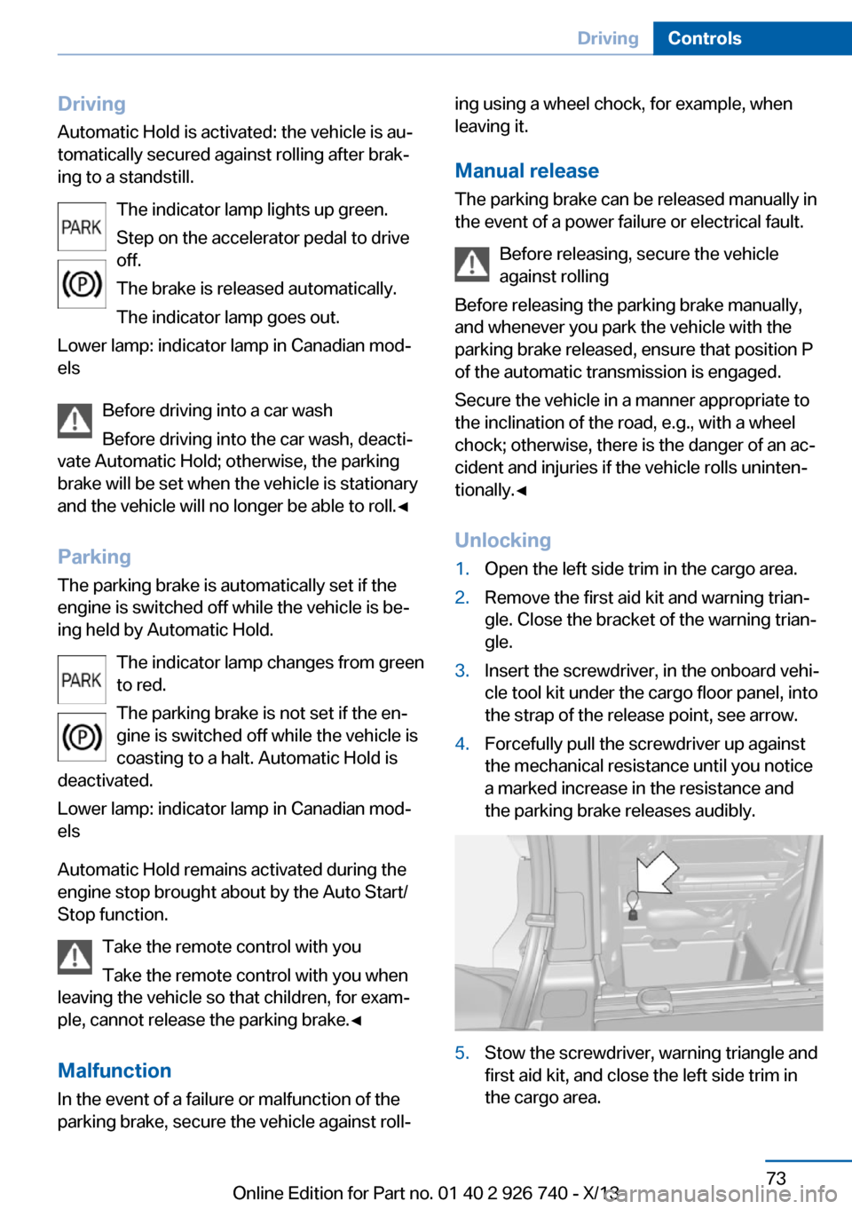
Unlocking1.Open the left side trim in the cargo area.2.Remove the first aid kit and warning trian‐
gle. Close the bracket of the warning trian‐
gle.3.Insert the screwdriver, in the onboard vehi‐
cle tool kit under the cargo floor panel, into
the strap of the release point, see arrow.4.Forcefully pull the screwdriver up against
the mechanical resistance until you notice
a marked increase in the resistance and
the parking brake releases audibly.5.Stow the screwdriver, warning triangle and
first aid kit, and close the left side trim in
the cargo area.Seite 73DrivingControls73
Online Edition for Part no. 01 40 2 926 740 - X/13
Page 131 of 265
Driving stability control systemsVehicle equipmentAll standard, country-specific and optional
equipment that is offered in the model series is
described in this chapter. Therefore, equip‐
ment is also described that is not available in a
vehicle, e. g., because of the selected optional
equipment or country variant. This also applies
for safety-related functions and systems.
Antilock Brake System ABS ABS prevents locking of the wheels during
braking.
The vehicle remains steerable even during full
brake applications, thus increasing active
safety.
ABS is operational every time you start the en‐
gine.
Brake assistant
When you apply the brakes rapidly, this system
automatically produces the maximum braking
force boost. This then reduces braking dis‐ tance to a minimum during full braking. This
system utilizes all of the benefits provided by ABS.
Do not reduce the pressure on the brake pedal
for the duration of the full braking.
When equipped with Driving Assistant Plus or
with Active Cruise Control with Stop & Go
function, ACC is supported by the braking in‐
tervention if there is a possible risk of collision.
To do this, the braking force is automatically increased if the braking pressure is insufficient
when the brakes are applied.Drive-off assistant
This system supports driving away on gradi‐
ents. The parking brake is not required.1.Hold the vehicle in place with the foot
brake.2.Release the foot brake and drive away
without delay.
After the foot brake is released, the vehicle is
held in place for approx. 2 seconds.
Depending on the vehicle load or when a trailer
is being used, the vehicle may roll back
slightly.
Driving off without delay
After releasing the foot brake, start driv‐
ing without delay, since the drive-off assistant
will not hold the vehicle in place for more than
approx. 2 seconds and the vehicle will begin
rolling back.◀
Automatic Differential Brake
The system controls the driving force by auto‐
matic braking intervention on individual
wheels. The function corresponds to a differ‐
ential lock: the system detects if a wheel be‐
gins to spin, because of loose road surface, for
example, and automatically brakes it.
The driving force is diverted to the wheel with
better traction.
As a result, the engine force is transferred
more efficiently to the wheels during accelera‐
tions.
Seite 131Driving stability control systemsControls131
Online Edition for Part no. 01 40 2 926 740 - X/13
Page 182 of 265
Storage compartmentsVehicle equipmentAll standard, country-specific and optional
equipment that is offered in the model series is
described in this chapter. Therefore, equip‐
ment is also described that is not available in a
vehicle, e. g., because of the selected optional
equipment or country variant. This also applies
for safety-related functions and systems.
Notes No loose objects in the passenger com‐
partment
Do not stow any objects in the passenger
compartment without securing them; other‐
wise, they may present a danger to occupants
for instance during braking and avoidance ma‐
neuvers.◀
Do not place anti-slip mats on the dash‐
board
Do not place anti-slip mats on the dashboard.
The mat materials could damage the dash‐
board.◀
Storage compartments
The following storage compartments are avail‐
able in the vehicle interior:▷Glove compartment on the front passenger
side, refer to page 182.▷Glove compartment on the driver's side,
refer to page 183.▷Compartments in the doors, refer to
page 183.▷Storage compartment on the center arm‐
rest, refer to page 183.▷Center armrest, refer to page 183▷Glasses compartment, refer to page 184.Glove compartment
Front passenger side
Note Close the glove compartment again im‐
mediately
Close the glove compartment immediately af‐
ter use while driving; otherwise, injury may oc‐
cur during accidents.◀
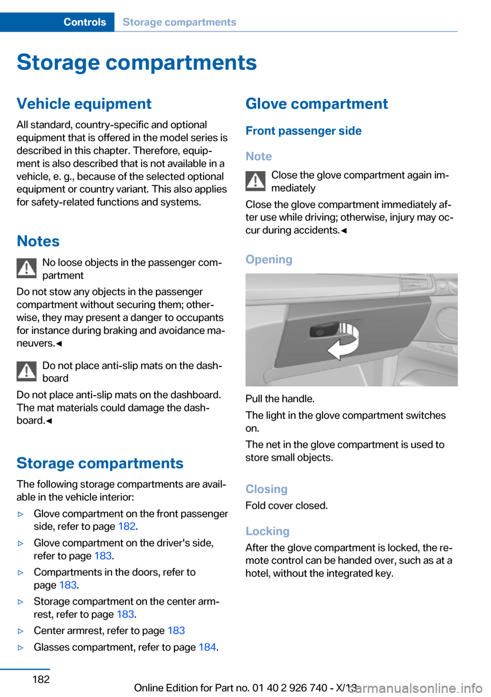
Opening
Pull the handle.
The light in the glove compartment switches
on.
The net in the glove compartment is used to
store small objects.
Closing Fold cover closed.
Locking After the glove compartment is locked, the re‐
mote control can be handed over, such as at a
hotel, without the integrated key.
Seite 182ControlsStorage compartments182
Online Edition for Part no. 01 40 2 926 740 - X/13
Page 204 of 265
RefuelingVehicle equipment
All standard, country-specific and optional
equipment that is offered in the model series is
described in this chapter. Therefore, equip‐
ment is also described that is not available in a
vehicle, e. g., because of the selected optional
equipment or country variant. This also applies
for safety-related functions and systems.
Hints Refuel promptly
Refuel no later than at a range of
30 miles/50 km, or operation of the engine is
not ensured and damage may occur.◀
Diesel engines The filler neck is designed for refueling at die‐
sel fuel pumps.
Fuel cap
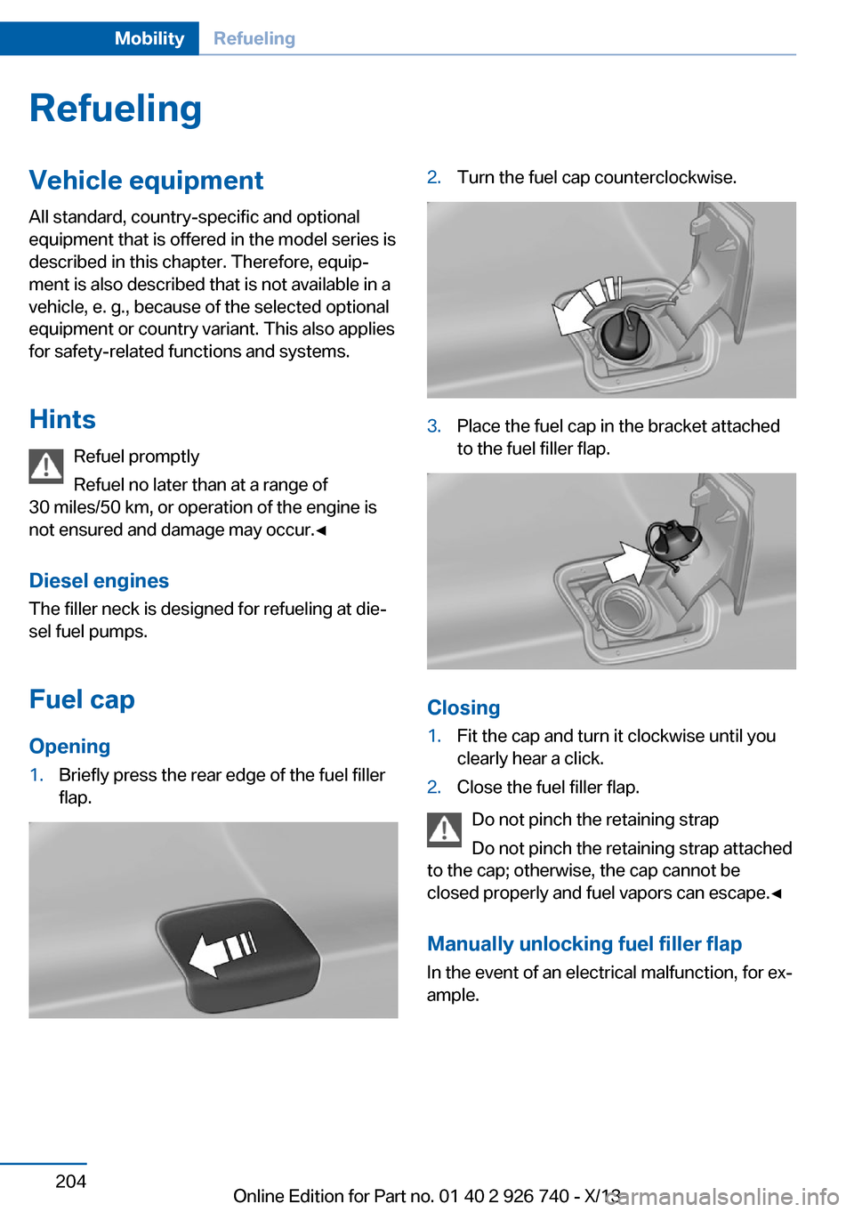
Opening1.Briefly press the rear edge of the fuel filler
flap.2.Turn the fuel cap counterclockwise.3.Place the fuel cap in the bracket attached
to the fuel filler flap.
Closing
1.Fit the cap and turn it clockwise until you
clearly hear a click.2.Close the fuel filler flap.
Do not pinch the retaining strap
Do not pinch the retaining strap attached
to the cap; otherwise, the cap cannot be
closed properly and fuel vapors can escape.◀
Manually unlocking fuel filler flap In the event of an electrical malfunction, for ex‐
ample.
Seite 204MobilityRefueling204
Online Edition for Part no. 01 40 2 926 740 - X/13