ESP BMW X5 2015 F15 Owners Manual
[x] Cancel search | Manufacturer: BMW, Model Year: 2015, Model line: X5, Model: BMW X5 2015 F15Pages: 275, PDF Size: 6.46 MB
Page 229 of 275
Engine compartmentVehicle features and optionsThis chapter describes all standard, country-
specific and optional features offered with the
series. It also describes features that are not
necessarily available in your car, e. g., due tothe selected options or country versions. This
also applies to safety-related functions and
systems. The respectively applicable country
provisions must be observed when using the
respective features and systems.
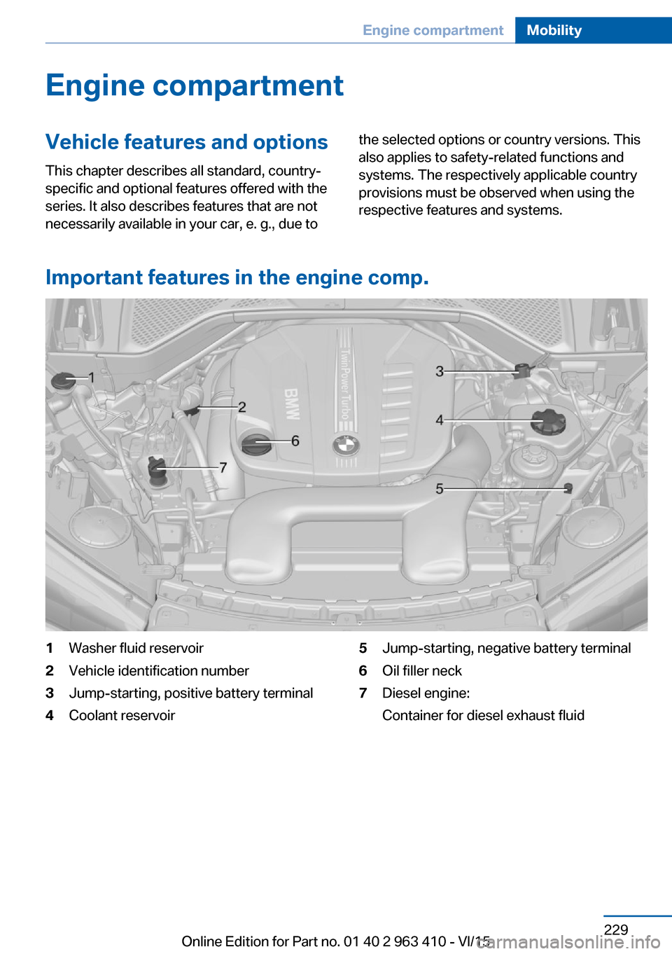
Important features in the engine comp.
1Washer fluid reservoir2Vehicle identification number3Jump-starting, positive battery terminal4Coolant reservoir5Jump-starting, negative battery terminal6Oil filler neck7Diesel engine:
Container for diesel exhaust fluidSeite 229Engine compartmentMobility229
Online Edition for Part no. 01 40 2 963 410 - VI/15
Page 232 of 275
Engine oilVehicle features and options
This chapter describes all standard, country-
specific and optional features offered with the
series. It also describes features that are not
necessarily available in your car, e. g., due to
the selected options or country versions. This
also applies to safety-related functions and
systems. The respectively applicable country
provisions must be observed when using the
respective features and systems.
General information The engine oil consumption is dependent on
the driving style and driving conditions.
The engine oil consumption can increase in
the following situations, for example:▷Sporty driving style.▷Break-in of the engine.▷Idling of the engine.▷With use of engine oil types that are not
approved.
Therefore, regularly check the engine oil level
after refueling.
The vehicle is equipped with electronic oil
measurement.
The electronic oil measurement has two meas‐
uring principles:
▷Status display▷Detailed measurementElectronic oil measurement
Status display
The concept
The engine oil level is monitored electronically
while driving and shown on the Control Dis‐
play.
If the engine oil level reaches the minimum
level, a check control message is displayed.
Requirements
A current measured value is available after ap‐
prox. 30 minutes of driving. During a shorter
trip, the status of the last, sufficiently long trip
is displayed.
With frequent short-distance trips, regularly
perform a detailed measurement.
Displaying the engine oil level
On the Control Display:1."Vehicle info"2."Vehicle status"3. "Engine oil level"
Engine oil level display messages
CAUTION
A too low engine oil level causes engine
damage. There is risk of property damage. Im‐
mediately add engine oil.◀
Take care not to add too much engine oil. CAUTION
Too much engine oil can damage the en‐
gine or the catalytic converter. There is risk of
property damage. Do not add too much engine
oil. Have too much engine oil siphoned off by a
dealer’s service center or another qualified
service center or repair shop.◀
Seite 232MobilityEngine oil232
Online Edition for Part no. 01 40 2 963 410 - VI/15
Page 236 of 275
CoolantVehicle features and optionsThis chapter describes all standard, country-
specific and optional features offered with the
series. It also describes features that are not
necessarily available in your car, e. g., due to
the selected options or country versions. This
also applies to safety-related functions and
systems. The respectively applicable country
provisions must be observed when using the
respective features and systems.
Information WARNING
With the engine hot and the cooling sys‐
tem open, coolant can escape and lead to
burns. There is risk of injuries. Only open the
cooling system with the engine cooled down.◀
WARNING
Additives are harmful and incorrect addi‐
tives can damage the engine. There is risk of
injuries and risk of property damage. Avoid the
contact of articles of clothing, skin or eyes with
additives. Do not swallow any additives. Use
suitable additives only.◀
Coolant consists of water and additives.
Not all commercially available additives are
suitable for the vehicle. Information about suit‐
able additives is available from a dealer’s serv‐
ice center or another qualified service center or
repair shop.
Coolant level
General information
If there is no Min. and Max. mark in the filler
neck of the coolant reservoir, have the coolant
level checked if needed by your dealer’s serv‐ice center or another qualified service center or
repair shop and add coolant as needed.
Overview
Depending on the engine installation, the cool‐
ant reservoir is located on the right side or the
left side of the engine compartment.
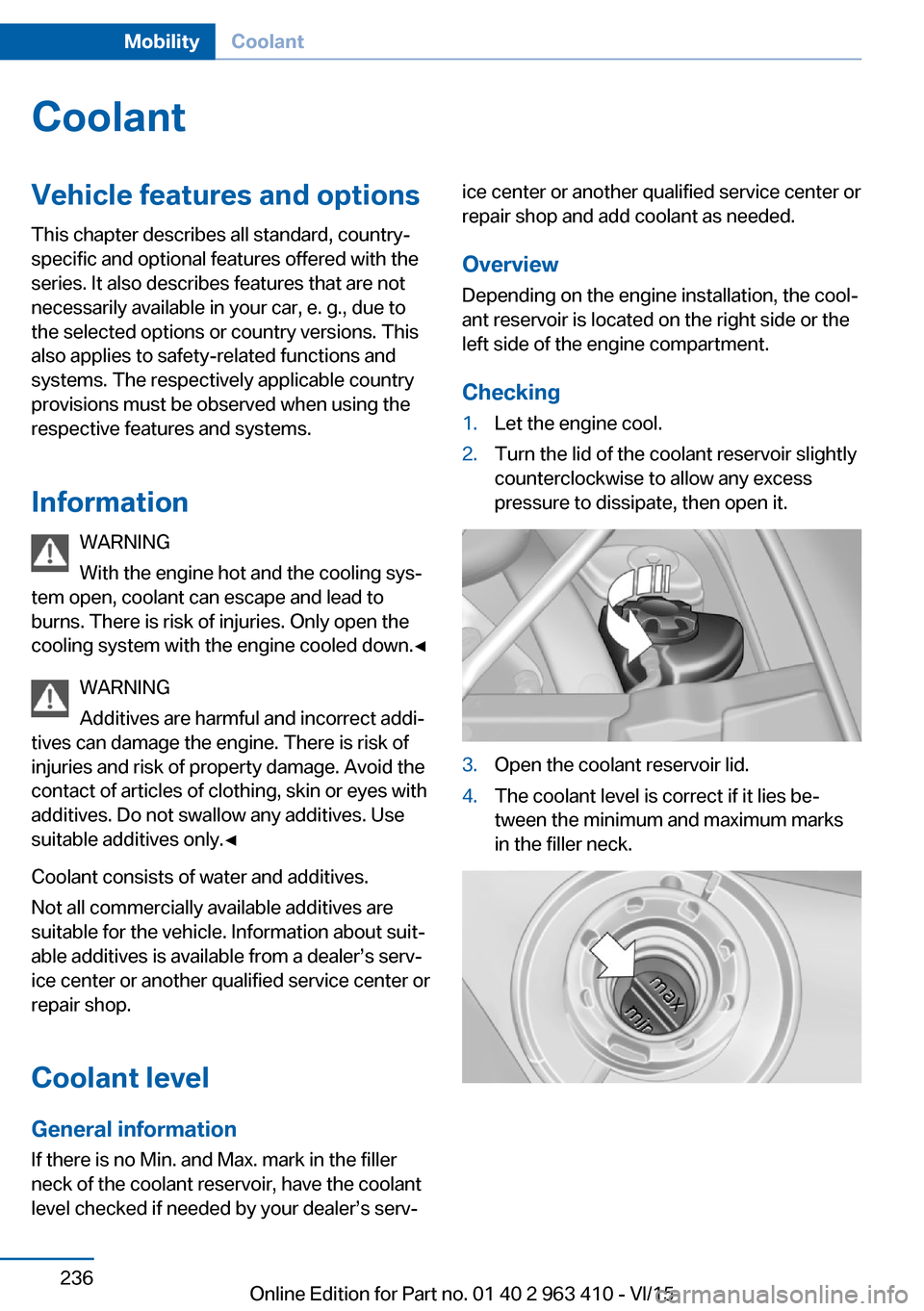
Checking1.Let the engine cool.2.Turn the lid of the coolant reservoir slightly
counterclockwise to allow any excess
pressure to dissipate, then open it.3.Open the coolant reservoir lid.4.The coolant level is correct if it lies be‐
tween the minimum and maximum marks
in the filler neck.Seite 236MobilityCoolant236
Online Edition for Part no. 01 40 2 963 410 - VI/15
Page 238 of 275
MaintenanceVehicle features and options
This chapter describes all standard, country-
specific and optional features offered with the
series. It also describes features that are not
necessarily available in your car, e. g., due to
the selected options or country versions. This
also applies to safety-related functions and
systems. The respectively applicable country
provisions must be observed when using the
respective features and systems.
BMW maintenance system The maintenance system indicates required
maintenance measures, and thereby provides
support in maintaining road safety and the op‐
erational reliability of the vehicle.
In some cases scopes and intervals may vary
according to the country-specific version. Re‐
placement work, spare parts, fuels and lubri‐
cants and wear materials are calculated sepa‐
rately. Further information is available from a
dealer’s service center or another qualified
service center or repair shop.
Condition Based ServiceCBS
Sensors and special algorithms take into ac‐
count the driving conditions of your vehicle.
Based on this, Condition Based Service recog‐
nizes the maintenance requirements.
The system makes it possible to adapt the
amount of maintenance corresponding to your
user profile.
Detailed information on service requirements,
refer to page 95, can be displayed on the Con‐
trol Display.Service data in the remote control
Information on the required maintenance is
continuously stored in the remote control. The dealer’s service center can read this data out
and suggest an optimized maintenance scope
for your vehicle.
Therefore, hand the service advisor the remote
control with which the vehicle was driven most
recently.
Storage periods Storage periods during which the vehicle bat‐
tery was disconnected are not taken into ac‐
count.
If this occurs, have a dealer's service center or
another qualified service center or repair shop
update the time-dependent maintenance pro‐
cedures, such as checking brake fluid and, if
necessary, changing the engine oil and the mi‐
crofilter/activated-charcoal filter.
Service and WarrantyInformation Booklet for US
models and Warranty and
Service Guide Booklet for
Canadian models
Please consult your Service and Warranty In‐
formation Booklet for US models and Warranty
and Service Guide Booklet for Canadian mod‐
els for additional information on service re‐
quirements.
The manufacturer of your vehicle recommends
that maintenance and repair be performed by a
dealer’s service center or another qualified
service center or repair shop. Records of regu‐
lar maintenance and repair work should be re‐
tained.Seite 238MobilityMaintenance238
Online Edition for Part no. 01 40 2 963 410 - VI/15
Page 240 of 275
Replacing componentsVehicle features and optionsThis chapter describes all standard, country-
specific and optional features offered with the
series. It also describes features that are not
necessarily available in your car, e. g., due to
the selected options or country versions. This
also applies to safety-related functions and
systems. The respectively applicable country
provisions must be observed when using the
respective features and systems.
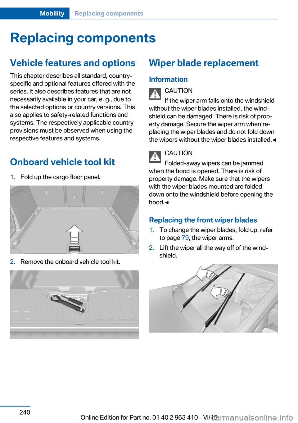
Onboard vehicle tool kit1.Fold up the cargo floor panel.2.Remove the onboard vehicle tool kit.Wiper blade replacement Information CAUTION
If the wiper arm falls onto the windshield
without the wiper blades installed, the wind‐
shield can be damaged. There is risk of prop‐
erty damage. Secure the wiper arm when re‐
placing the wiper blades and do not fold down
the wipers without the wiper blades installed.◀
CAUTION
Folded-away wipers can be jammed
when the hood is opened. There is risk of
property damage. Make sure that the wipers
with the wiper blades mounted are folded
down onto the windshield before opening the
hood.◀
Replacing the front wiper blades1.To change the wiper blades, fold up, refer
to page 79, the wiper arms.2.Lift the wiper all the way off of the wind‐
shield.Seite 240MobilityReplacing components240
Online Edition for Part no. 01 40 2 963 410 - VI/15
Page 242 of 275
placement be performed by a dealer’s service
center or another qualified service center or re‐
pair shop.◀
Light-emitting diodes (LEDs)
Some items of equipment use light-emitting
diodes installed behind a cover as a light
source.
These light-emitting diodes, which are related
to conventional lasers, are officially designated
as Class 1 light-emitting diodes.
WARNING
Too intensive brightness can irritate or
damage the retina of the eye. There is risk of
injuries. Do not look directly into the headlights
or other light sources for an extended period of
time. Do not remove the LED covers.◀
Headlight glass
Condensation can form on the inside of the ex‐
ternal lights in cool or humid weather. When
driving with the lights switched on, the con‐
densation evaporates after a short time. The
headlight glass does not need to be changed.
If despite driving with the lights switched on,
increasing humidity forms, e. g. water droplets
in the lamp, the manufacturer of your vehicle
recommends having it checked by a dealer’s
service center or another qualified service cen‐
ter or repair shop.
Headlight setting The headlight adjustments can be affected by
changing lights and bulbs. After the headlight
adjustment was changed, have it checked and,
if necessary, corrected by a dealer’s service
center or another qualified service center or re‐
pair shop.Front lights, bulb replacement
Xenon headlights
Information
Because of the long service life of these bulbs,
the likelihood of failure is very low. Switching
the lights on and off frequently shortens their
service life.
If a bulb fails, turn on the front fog lights and
continue the trip with great care. Comply with local regulations.
DANGER
There can be high voltage in the lighting
system. There is danger to life. The manufac‐
turer of your vehicle recommends that the work on the lighting system including bulb re‐
placement be performed by a dealer’s service
center or another qualified service center or re‐
pair shop.◀
For checking and adjusting headlamp aim,
contact a dealer’s service center or another
qualified service center or repair shop.
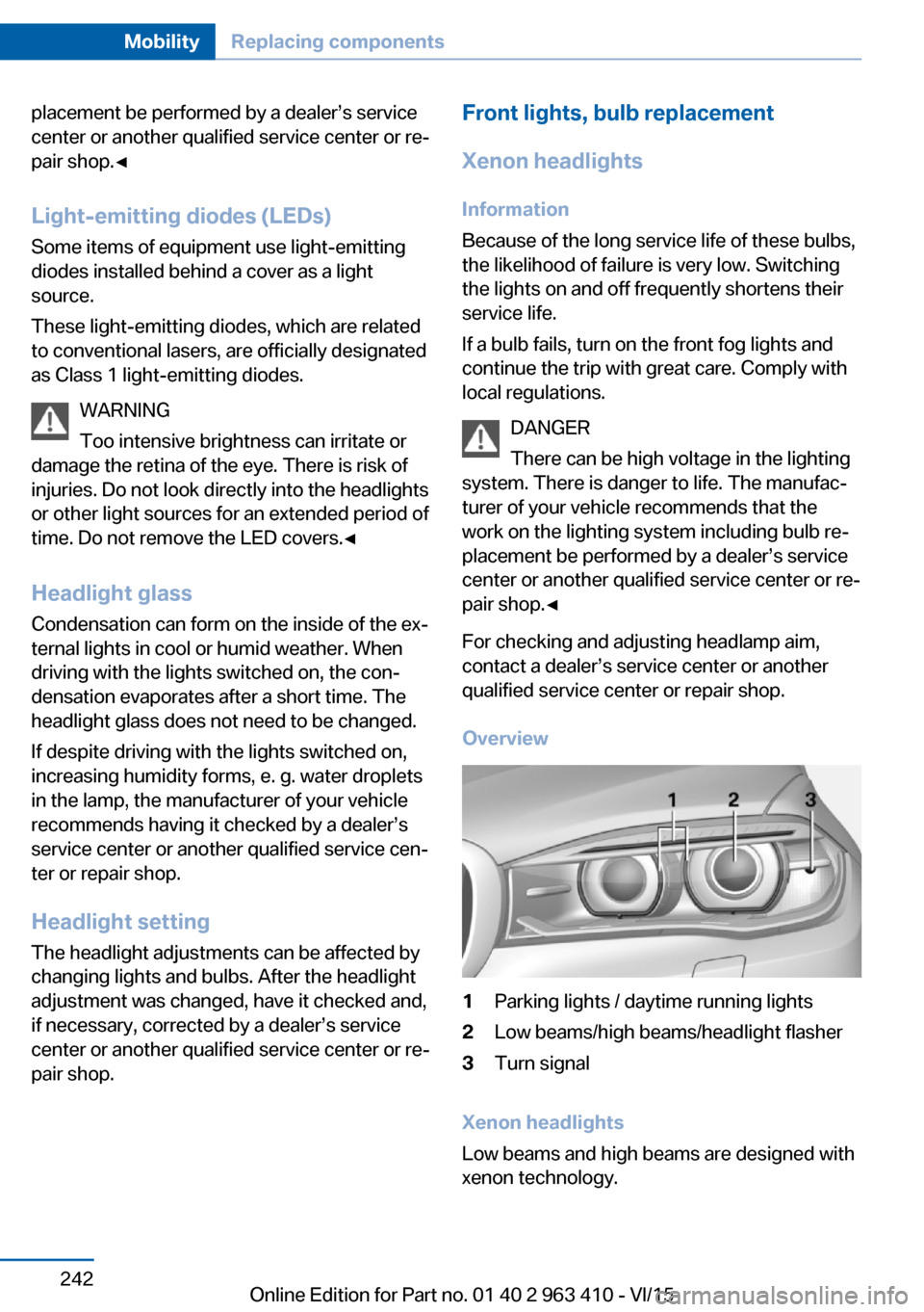
Overview1Parking lights / daytime running lights2Low beams/high beams/headlight flasher3Turn signal
Xenon headlights
Low beams and high beams are designed with
xenon technology.
Seite 242MobilityReplacing components242
Online Edition for Part no. 01 40 2 963 410 - VI/15
Page 248 of 275
Breakdown assistanceVehicle features and options
This chapter describes all standard, country-
specific and optional features offered with the
series. It also describes features that are not
necessarily available in your car, e. g., due to
the selected options or country versions. This
also applies to safety-related functions and
systems. The respectively applicable country
provisions must be observed when using the
respective features and systems.
Hazard warning flashers
The button is located in the center console.
Intelligent Emergency
Request
The concept In case of an emergency, an Emergency Re‐
quest can be made through this system.
General information
Only press the SOS button in an emergency.
For technical reasons, the Emergency Request
cannot be guaranteed under unfavorable con‐
ditions.
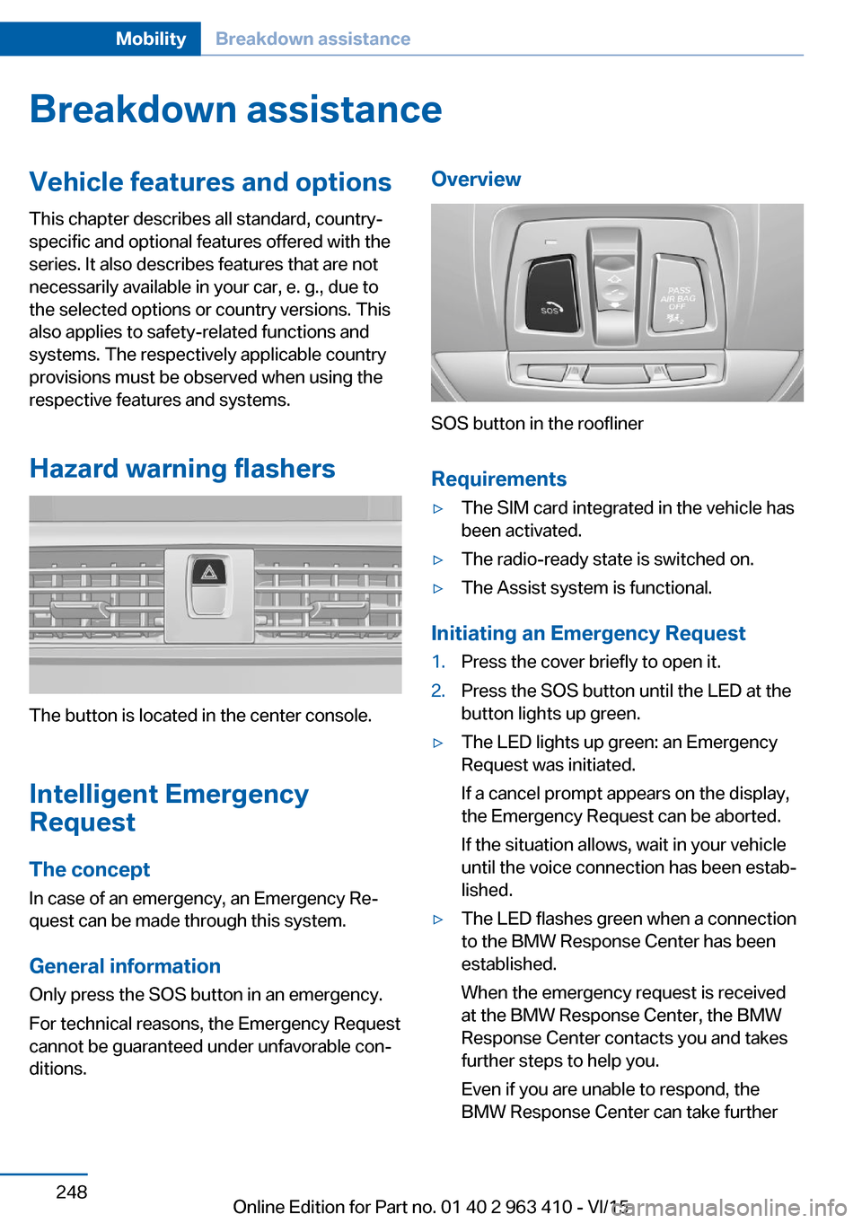
Overview
SOS button in the roofliner
Requirements
▷The SIM card integrated in the vehicle has
been activated.▷The radio-ready state is switched on.▷The Assist system is functional.
Initiating an Emergency Request
1.Press the cover briefly to open it.2.Press the SOS button until the LED at the
button lights up green.▷The LED lights up green: an Emergency
Request was initiated.
If a cancel prompt appears on the display,
the Emergency Request can be aborted.
If the situation allows, wait in your vehicle
until the voice connection has been estab‐
lished.▷The LED flashes green when a connection
to the BMW Response Center has been
established.
When the emergency request is received
at the BMW Response Center, the BMW
Response Center contacts you and takes
further steps to help you.
Even if you are unable to respond, the
BMW Response Center can take furtherSeite 248MobilityBreakdown assistance248
Online Edition for Part no. 01 40 2 963 410 - VI/15
Page 249 of 275
steps to help you under certain circum‐
stances.
For this, data are transmitted to the BMW
Response Center which serve to deter‐
mine the necessary rescue measures. E. g.
the current position of the vehicle, if it can
be established.▷If the LED is flashing green, but the BMW
Response Center can no longer be heard
via the speaker, you can nevertheless still
be heard at the BMW Response Center.
Initiating an Emergency Request
automatically
Under certain conditions, an Emergency Re‐
quest is automatically initiated immediately af‐
ter a severe accident. Automatic Collision Noti‐
fication is not affected by pressing the SOS
button.
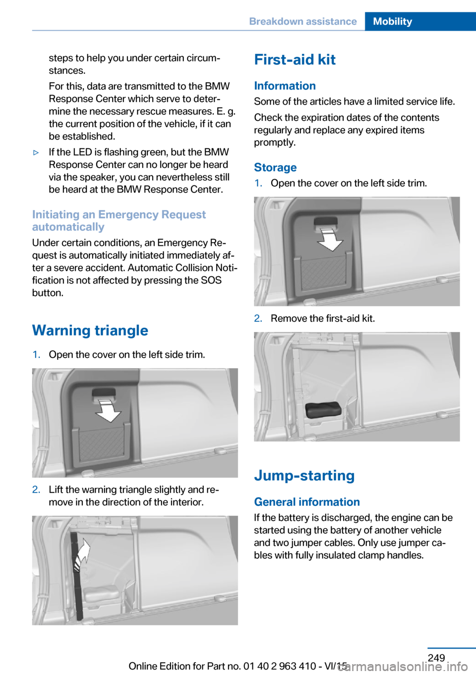
Warning triangle
1.Open the cover on the left side trim.2.Lift the warning triangle slightly and re‐
move in the direction of the interior.First-aid kit
Information
Some of the articles have a limited service life.
Check the expiration dates of the contents
regularly and replace any expired items
promptly.
Storage1.Open the cover on the left side trim.2.Remove the first-aid kit.
Jump-starting
General information If the battery is discharged, the engine can be
started using the battery of another vehicle
and two jumper cables. Only use jumper ca‐
bles with fully insulated clamp handles.
Seite 249Breakdown assistanceMobility249
Online Edition for Part no. 01 40 2 963 410 - VI/15
Page 250 of 275
InformationDANGER
Contact with live components can lead to
an electric shock. There is risk of injuries or
danger to life. Do not touch any components
that are under voltage.◀
To prevent personal injury or damage to both
vehicles, adhere strictly to the following proce‐
dure.
Preparation CAUTION
In the case of body contact between the
two vehicles, a short circuit can occur during
jump-starting. There is risk of property dam‐
age. Make sure that no body contact occurs.◀1.Check whether the battery of the other ve‐
hicle has a voltage of 12 volts. This infor‐
mation can be found on the battery.2.Switch off the engine of the assisting vehi‐
cle.3.Switch off any electronic systems/power
consumers in both vehicles.
Starting aid terminals
WARNING
If the jumper cables are connected in the
incorrect order, sparks formation can occur.
There is risk of injuries. Pay attention to the
correct order during connection.◀
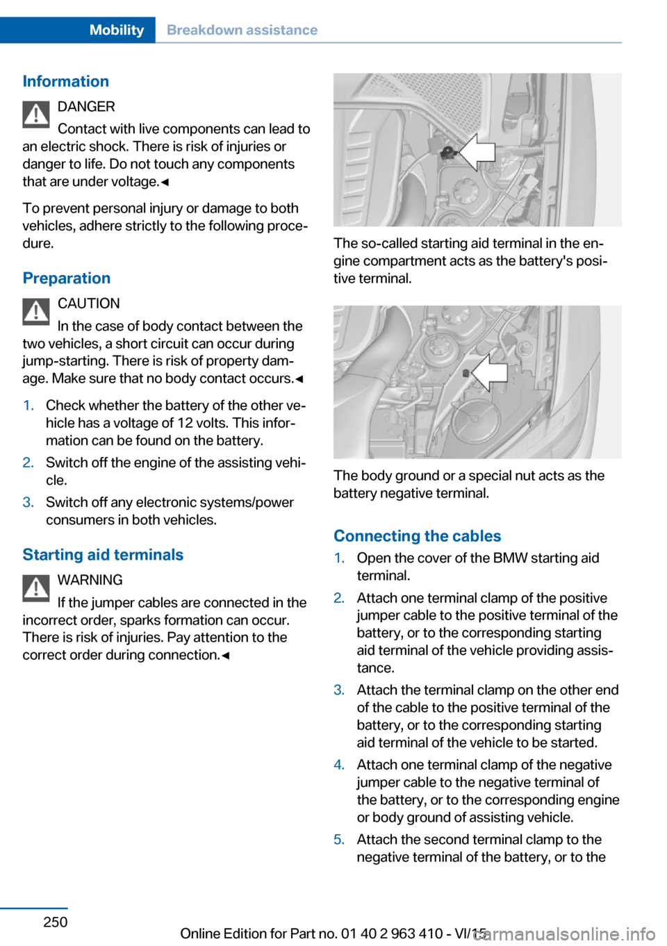
The so-called starting aid terminal in the en‐
gine compartment acts as the battery's posi‐
tive terminal.
The body ground or a special nut acts as the
battery negative terminal.
Connecting the cables
1.Open the cover of the BMW starting aid
terminal.2.Attach one terminal clamp of the positive
jumper cable to the positive terminal of the
battery, or to the corresponding starting
aid terminal of the vehicle providing assis‐
tance.3.Attach the terminal clamp on the other end
of the cable to the positive terminal of the
battery, or to the corresponding starting
aid terminal of the vehicle to be started.4.Attach one terminal clamp of the negative
jumper cable to the negative terminal of
the battery, or to the corresponding engine
or body ground of assisting vehicle.5.Attach the second terminal clamp to the
negative terminal of the battery, or to theSeite 250MobilityBreakdown assistance250
Online Edition for Part no. 01 40 2 963 410 - VI/15
Page 251 of 275
corresponding engine or body ground of
the vehicle to be started.
Starting the engine
Never use spray fluids to start the engine.
1.Start the engine of the assisting vehicle
and let it run for several minutes at an in‐
creased idle speed.
If the vehicle to be started has a diesel en‐
gine: let the engine of the assisting vehicle
run for approx. 10 minutes.2.Start the engine of the vehicle that is to be
started in the usual way.
If the first starting attempt is not success‐
ful, wait a few minutes before making an‐
other attempt in order to allow the dis‐
charged battery to recharge.3.Let both engines run for several minutes.4.Disconnect the jumper cables in the re‐
verse order.
Check the battery and recharge if needed.
Tow-starting and towing Information WARNING
Due to system limits, individual functions
can malfunction during tow-starting/towing
with the Intelligent Safety systems activated,
e.g. approach control warning with light brak‐
ing function. There is risk of an accident.
Switch all Intelligent Safety systems off prior to
tow-starting/towing.◀
Transporting the vehicle
Information CAUTION
The vehicle can be damaged when tow‐
ing the vehicle with a single lifted axle. There is
risk of property damage. The vehicle should
only be transported on a loading platform.◀
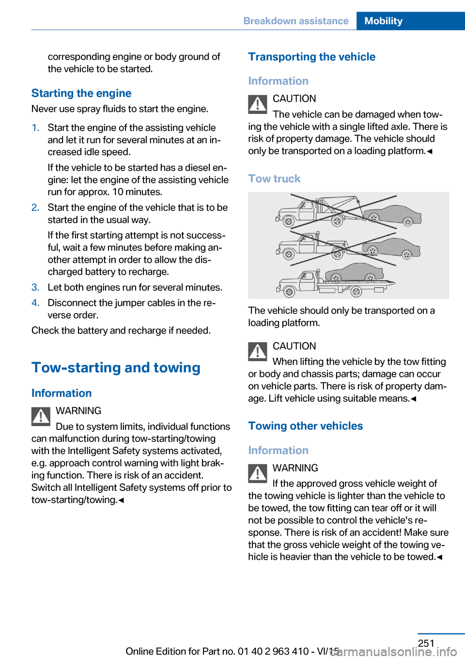
Tow truck
The vehicle should only be transported on a
loading platform.
CAUTION
When lifting the vehicle by the tow fitting
or body and chassis parts; damage can occur
on vehicle parts. There is risk of property dam‐
age. Lift vehicle using suitable means.◀
Towing other vehicles
Information WARNING
If the approved gross vehicle weight of
the towing vehicle is lighter than the vehicle to
be towed, the tow fitting can tear off or it will
not be possible to control the vehicle's re‐
sponse. There is risk of an accident! Make sure
that the gross vehicle weight of the towing ve‐
hicle is heavier than the vehicle to be towed.◀
Seite 251Breakdown assistanceMobility251
Online Edition for Part no. 01 40 2 963 410 - VI/15