Level BMW X5 2015 F15 User Guide
[x] Cancel search | Manufacturer: BMW, Model Year: 2015, Model line: X5, Model: BMW X5 2015 F15Pages: 275, PDF Size: 6.46 MB
Page 115 of 275
longer and the self-steering properties will
change. There is risk of an accident.
Drive moderately and do not exceed a speed of
50 mph/80 km/h.◀
Final tire failure
Vibrations or loud noises while driving can indi‐
cate the final failure of a tire.
Reduce speed and stop; otherwise, pieces of
the tire could come loose and cause an acci‐
dent.
Do not continue driving. Contact a dealer’s
service center or another qualified service cen‐
ter or repair shop.
Required tire inflation pressure check
message
A Check Control message is displayed in the
following situations▷The system has detected a wheel change,
but no reset was done.▷Inflation was not carried out according to
specifications.▷The tire inflation pressure has fallen below
the level of the last confirmation.
In this case:
▷Check the tire pressure and correct as
needed.▷Carry out a reset of the system after a tire
change.
System limits
The system does not function properly if a re‐
set has not been carried out, e.g., a flat tire is
reported though tire inflation pressures are
correct.
The tire inflation pressure depends on the
tire's temperature. Driving or exposure to the
sun will increase the tire's temperature, thus
increasing the tire inflation pressure. The tire
inflation pressure is reduced when the tire
temperature falls again. These circumstances
may cause a warning when temperatures fall
very sharply.
The system cannot indicate sudden serious
tire damage caused by external circumstances.
Malfunction The yellow warning lamp flashes and
then lights up continuously. A Check
Control message is displayed. No flat
tire or loss of tire inflation pressure can be de‐
tected.
Examples and recommendations in the follow‐
ing situations:▷A wheel without TPM electronics is
mounted: Have it checked by a dealer’s
service center or another qualified service
center or repair shop as needed.▷Malfunction: Have system checked by a
dealer’s service center or another qualified
service center or repair shop.▷TPM was unable to complete the reset.
Reset the system again.▷Interference through systems or devices
with the same radio frequency: After leav‐
ing the area of the interference, the system
automatically becomes active again.
Declaration according to NHTSA/
FMVSS 138 Tire Pressure Monitoring
System
Each tire, including the spare (if provided)
should be checked monthly when cold and in‐
flated to the inflation pressure recommended
by the vehicle manufacturer on the vehicle
placard or tire inflation pressure label. (If your
vehicle has tires of a different size than the size
indicated on the vehicle placard or tire inflation
pressure label, you should determine the
proper tire inflation pressure for those tires.)
As an added safety feature, your vehicle has
been equipped with a tire pressure monitoring
system (TPMS) that illuminates a low tire pres‐
sure telltale when one or more of your tires is
significantly under-inflated. Accordingly, when
Seite 115SafetyControls115
Online Edition for Part no. 01 40 2 963 410 - VI/15
Page 116 of 275
the low tire pressure telltale illuminates, you
should stop and check your tires as soon as
possible, and inflate them to the proper pres‐
sure. Driving on a significantly under-inflated
tire causes the tire to overheat and can lead to
tire failure. Under-inflation also reduces fuel ef‐
ficiency and tire tread life, and may affect the
vehicle's handling and stopping ability. Please
note that the TPMS is not a substitute for
proper tire maintenance, and it is the driver's
responsibility to maintain correct tire pressure,
even if under-inflation has not reached the
level to trigger illumination of the TPMS low
tire pressure telltale. Your vehicle has also
been equipped with a TPMS malfunction indi‐
cator to indicate when the system is not oper‐
ating properly. The TPMS malfunction indica‐
tor is combined with the low tire pressure
telltale. When the system detects a malfunc‐
tion, the telltale will flash for approximately one
minute and then remain continuously illumi‐
nated. This sequence will continue upon sub‐
sequent vehicle start-ups as long as the mal‐
function exists. When the malfunction indicator
is illuminated, the system may not be able to
detect or signal low tire pressure as intended.
TPMS malfunctions may occur for a variety of
reasons, including the installation of replace‐
ment or alternate tires or wheels on the vehicle
that prevent the TPMS from functioning prop‐
erly. Always check the TPMS malfunction tell‐
tale after replacing one or more tires or wheels
on your vehicle to ensure that the replacement
or alternate tires and wheels allow the TPMS
to continue to function properly.
FTM Flat Tire Monitor The conceptThe system detects tire inflation pressure losson the basis of rotation speed differences be‐
tween the individual wheels while driving.
In the event of a tire inflation pressure loss, the
diameter and therefore the rotational speed ofthe corresponding wheel changes. This will be
detected and reported as a flat tire.
The system does not measure the actual infla‐
tion pressure in the tires.
Functional requirements
The system must have been initialized when
the tire inflation pressure was correct; other‐
wise, reliable flagging of a flat tire is not as‐
sured. Initialize the system after each correc‐ tion of the tire inflation pressure and after
every tire or wheel change.
Status display
The current status of the Flat Tire Monitor can
be displayed on the Control Display, e.g.,
whether or not the FTM is active.
On the Control Display:1."Vehicle info"2."Vehicle status"3. "Flat Tire Monitor (FTM)"
The status is displayed.
Initialization
When initializing the once set inflation tire
pressures serve as reference values in order to
detect a flat tire. Initialization is started by con‐
firming the tire inflation pressures.
Do not initialize the system when driving with
snow chains.
On the Control Display:
1."Vehicle info"2."Vehicle status"3. "Perform reset"4.Start the engine - do not drive off.5.Start the initialization with "Perform reset".6.Drive away.
The initialization is completed while driving,
which can be interrupted at any time.
The initialization automatically continues when
driving resumes.
Seite 116ControlsSafety116
Online Edition for Part no. 01 40 2 963 410 - VI/15
Page 119 of 275
Intelligent Safety button
Switching on/off Some Intelligent Safety systems are automati‐
cally active after every departure. Some Intelli‐
gent Safety systems activate according to the
last setting.
Press button briefly:▷The menu for the intelligent safety
system is displayed. The systems
are individually switched off ac‐
cording to their respective set‐
tings.▷LED lights up orange or goes out respec‐
tive to their individual settings.
Adjust as needed. Individual settings are
stored for the profile currently used.
Press button again:
▷All Intelligent Safety systems are
activated.▷The LED lights up green.
Hold down button:
▷All Intelligent Safety systems are
turned off.▷The LED goes out.
Front-end collision warning
Depending on the equipment, the collision
warning system consists of one of the follow‐
ing functions:
▷Front-end collision warning with City Brak‐
ing function, refer to page 119.▷Front-end collision warning with braking
function, refer to page 122Front-end collision warning
with City Braking function
The concept The system can help prevent accidents. If an
accident cannot be prevented, the system will
help reduce the collision speed.
The system sounds a warning before an immi‐
nent collision and actuates brakes independ‐
ently if needed.
The automatic braking intervention is done
with limited force and duration.
A camera in the area of the rearview mirror
controls the system.
The front-end collision warning is available
even if cruise control has been deactivated.
With the vehicle approaching another vehicle
intentionally, the collision warning and braking
are delayed in order to avoid false system re‐
actions.
General information
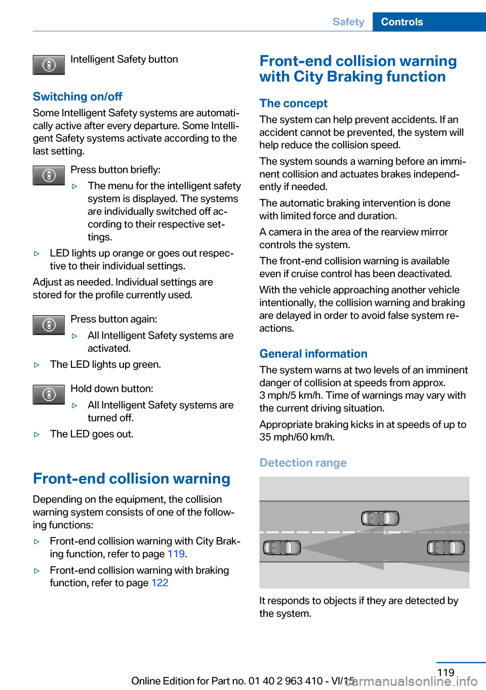
The system warns at two levels of an imminent
danger of collision at speeds from approx.
3 mph/5 km/h. Time of warnings may vary with
the current driving situation.
Appropriate braking kicks in at speeds of up to
35 mph/60 km/h.
Detection range
It responds to objects if they are detected by
the system.
Seite 119SafetyControls119
Online Edition for Part no. 01 40 2 963 410 - VI/15
Page 128 of 275
Warm objects have a light appearance and
cold objects a dark appearance.
The ability to detect an object depends on the
temperature difference between the object
and the background and on the level of heat
radiation emitted by the object. Objects that
are similar in temperature to the environment
or that radiate very little heat are difficult to de‐
tect.
For safety reasons, when driving at speeds
above approx. 3 mph/5 km/h and in low ambi‐
ent light, the image is only displayed when the
low beams are activated.
A still image is displayed at regular intervals for
a fraction of a second.
Pedestrian and animal detection
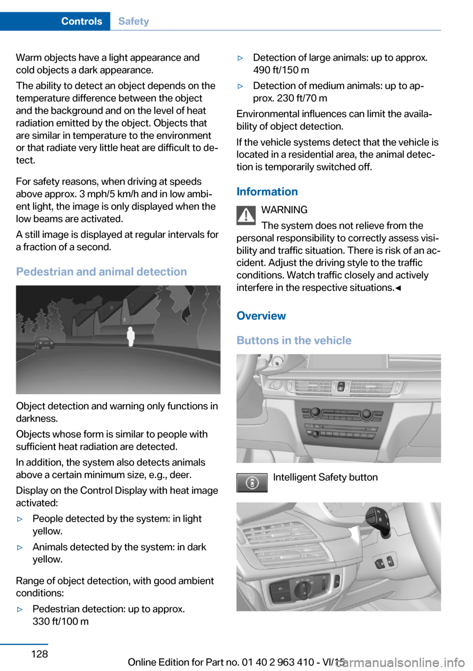
Object detection and warning only functions in
darkness.
Objects whose form is similar to people with
sufficient heat radiation are detected.
In addition, the system also detects animals
above a certain minimum size, e.g., deer.
Display on the Control Display with heat image
activated:
▷People detected by the system: in light
yellow.▷Animals detected by the system: in dark
yellow.
Range of object detection, with good ambient
conditions:
▷Pedestrian detection: up to approx.
330 ft/100 m▷Detection of large animals: up to approx.
490 ft/150 m▷Detection of medium animals: up to ap‐
prox. 230 ft/70 m
Environmental influences can limit the availa‐
bility of object detection.
If the vehicle systems detect that the vehicle is
located in a residential area, the animal detec‐
tion is temporarily switched off.
Information WARNING
The system does not relieve from the
personal responsibility to correctly assess visi‐
bility and traffic situation. There is risk of an ac‐
cident. Adjust the driving style to the traffic
conditions. Watch traffic closely and actively
interfere in the respective situations.◀
Overview
Buttons in the vehicle
Intelligent Safety button
Seite 128ControlsSafety128
Online Edition for Part no. 01 40 2 963 410 - VI/15
Page 141 of 275
Display in the instrument clusterThe selected speed is displayed
in the speedometer.▷Green: the system is actively
braking the vehicle.▷Orange: the system is on
standby.
Malfunction
A message is displayed in the instrument clus‐
ter. HDC is not available, e.g., due to elevated
brake temperatures.
Active Steering
Active Steering varies the steering angle of the
wheels in relation to the steering wheel move‐
ment as a function of the speed.
At lower speeds, for example during turning or
maneuvering, the steering angle is increased,
that is to say the steering becomes more di‐
rect.
At higher speeds, the steering angle is increas‐
ingly reduced.
This enables even more precise handling at
high speeds and more responsive steering
with reduced steering angle at low speeds.
Active roll stabilization The concept
The system reduces the lateral inclination of
the vehicle that occurs during rapid driving in
curves or during quick evasive maneuvers.
Driving stability and driving comfort are in‐
creased under all driving conditions. The sys‐
tem utilizes active stabilizer bars on the front
and rear axles that react immediately to all driv‐
ing situations.
Programs
The system offers two different programs.
Select the programs via the Driving Dynamics
Control, refer to page 142.
SPORT Sporty tuning for greater driving agility.
COMFORT
Comfort-oriented tuning for optimal comfort.
Vertical Dynamic Control The concept This system reduces undesirable vehicle mo‐
tion when using a dynamic driving style or trav‐
eling on uneven road surfaces.
The system enhances driving dynamics and
comfort fitting road surface and driving style.
Programs The system offers several different programs.
Select the programs via the Driving Dynamics
Control, refer to page 142.
SPORT/SPORT+
Consistently sporty control of the shock ab‐
sorbers for greater driving agility.
COMFORT/ECO PRO Balanced tuning.
Self-leveling suspension The concept
The self-leveling suspension keeps the vehicle
height and ground clearance constant. The
height of the vehicle at the rear axle is main‐
tained at a predefined level under all load con‐
ditions.Seite 141Driving stability control systemsControls141
Online Edition for Part no. 01 40 2 963 410 - VI/15
Page 158 of 275
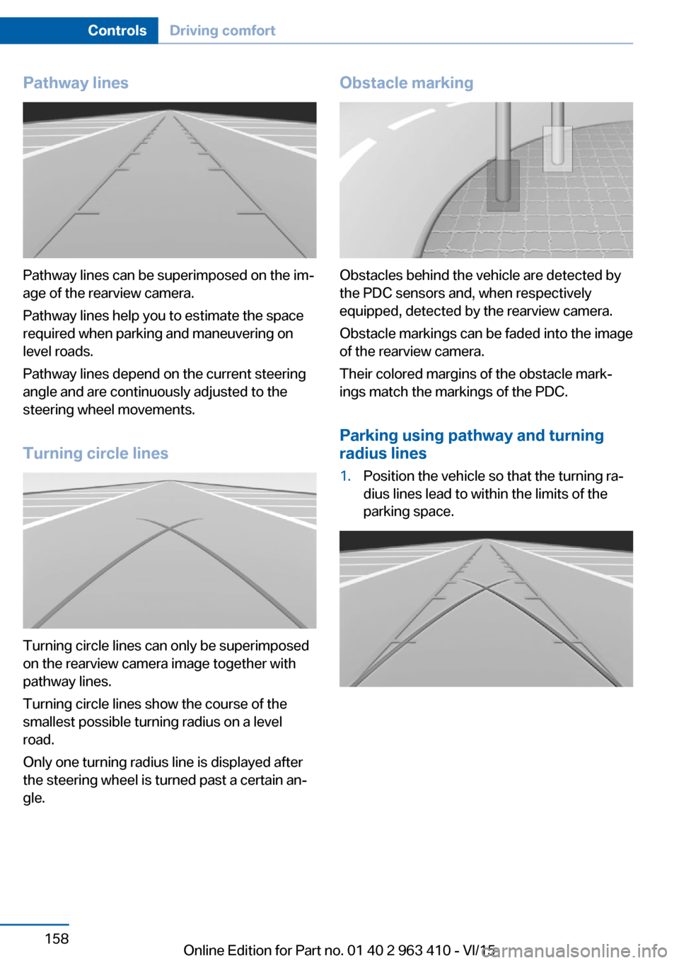
Pathway lines
Pathway lines can be superimposed on the im‐
age of the rearview camera.
Pathway lines help you to estimate the space
required when parking and maneuvering on
level roads.
Pathway lines depend on the current steering
angle and are continuously adjusted to the
steering wheel movements.
Turning circle lines
Turning circle lines can only be superimposed
on the rearview camera image together with
pathway lines.
Turning circle lines show the course of the
smallest possible turning radius on a level
road.
Only one turning radius line is displayed after
the steering wheel is turned past a certain an‐
gle.
Obstacle marking
Obstacles behind the vehicle are detected by
the PDC sensors and, when respectively
equipped, detected by the rearview camera.
Obstacle markings can be faded into the image
of the rearview camera.
Their colored margins of the obstacle mark‐
ings match the markings of the PDC.
Parking using pathway and turning
radius lines
1.Position the vehicle so that the turning ra‐
dius lines lead to within the limits of the
parking space.Seite 158ControlsDriving comfort158
Online Edition for Part no. 01 40 2 963 410 - VI/15
Page 179 of 275
USB interface for data
transfer
The concept Connection for importing and exporting data
on USB devices, e.g.:▷Personal Profile settings, refer to page 35.▷Music collection, see user's manual for
Navigation, Entertainment and Communi‐
cation.
Information
Observe the following when connecting:
▷Do not use force when plugging the con‐
nector into the USB interface.▷Do not connect devices such as fans or
lights to the USB interface.▷Do not connect USB hard drives.▷Do not use the USB interface for recharg‐
ing external devices.
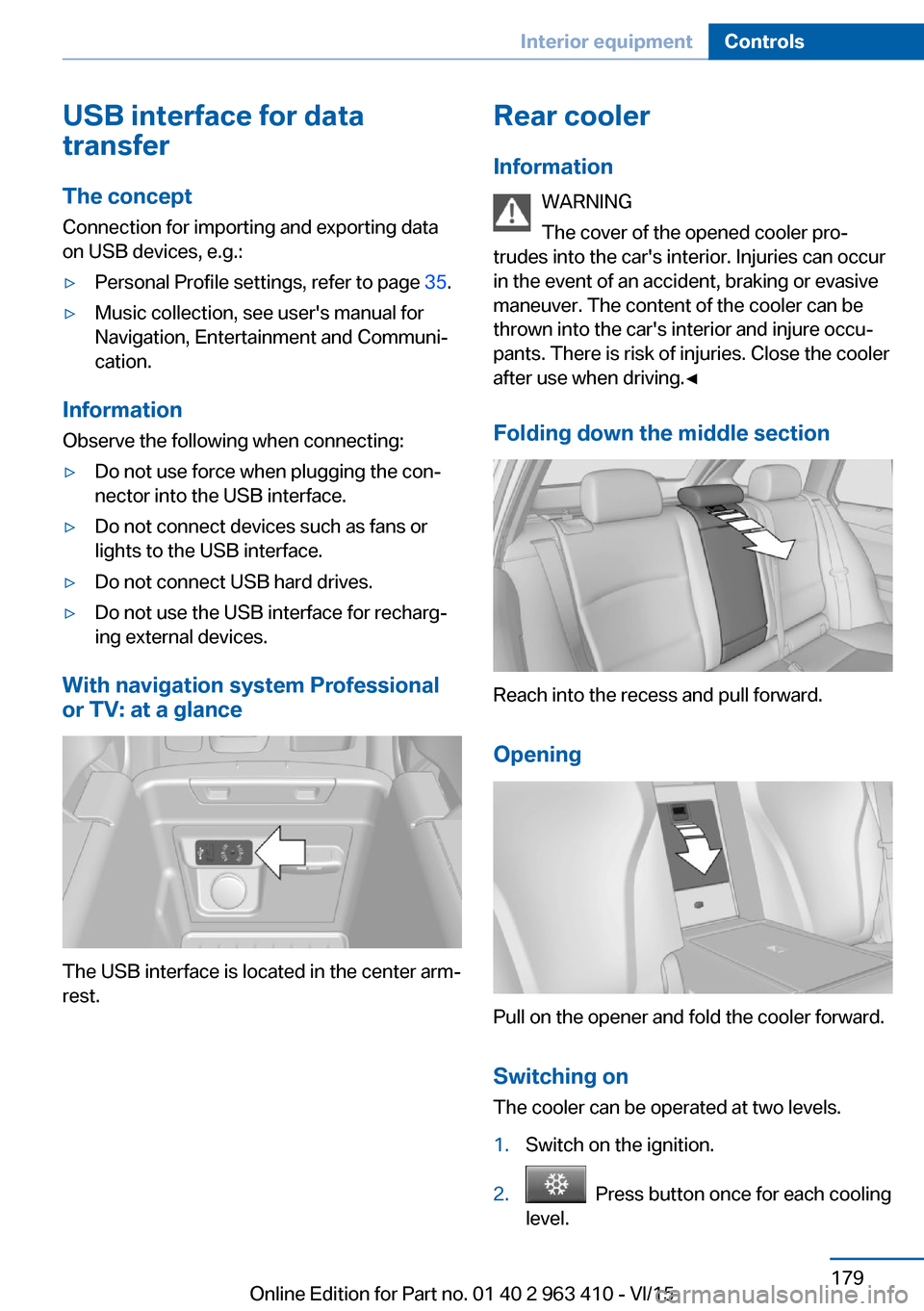
With navigation system Professional
or TV: at a glance
The USB interface is located in the center arm‐
rest.
Rear cooler
Information WARNING
The cover of the opened cooler pro‐
trudes into the car's interior. Injuries can occur
in the event of an accident, braking or evasive
maneuver. The content of the cooler can be
thrown into the car's interior and injure occu‐
pants. There is risk of injuries. Close the cooler
after use when driving.◀
Folding down the middle section
Reach into the recess and pull forward.
Opening
Pull on the opener and fold the cooler forward. Switching onThe cooler can be operated at two levels.
1.Switch on the ignition.2. Press button once for each cooling
level.
Seite 179Interior equipmentControls179
Online Edition for Part no. 01 40 2 963 410 - VI/15
Page 193 of 275
Hot exhaust systemWARNING
During driving operation, high tempera‐
tures can occur underneath the body, e.g.
caused by the exhaust gas system. If combus‐
tible materials, such as leaves or grass, come
in contact with hot parts of the exhaust gas
system, these materials can ignite. There is
risk of injuries or risk of property damage.
Do not remove the heat shields installed and
never apply undercoating to them. Make sure
that no combustible materials can come in
contact with hot vehicle parts in driving opera‐
tion, idle or during parking. Do not touch the
hot exhaust system.◀
Diesel particulate filter The diesel particulate filter collects soot parti‐
cles and burns them periodically at high tem‐
peratures.
During several minutes of cleaning the follow‐
ing may occur:▷Temporarily, the engine may run less
smoothly.▷Noises and a slight amount of smoke com‐
ing from the exhaust until shortly after the
engine is shut down.▷A somewhat higher engine speed is neces‐
sary to reach usual performance.
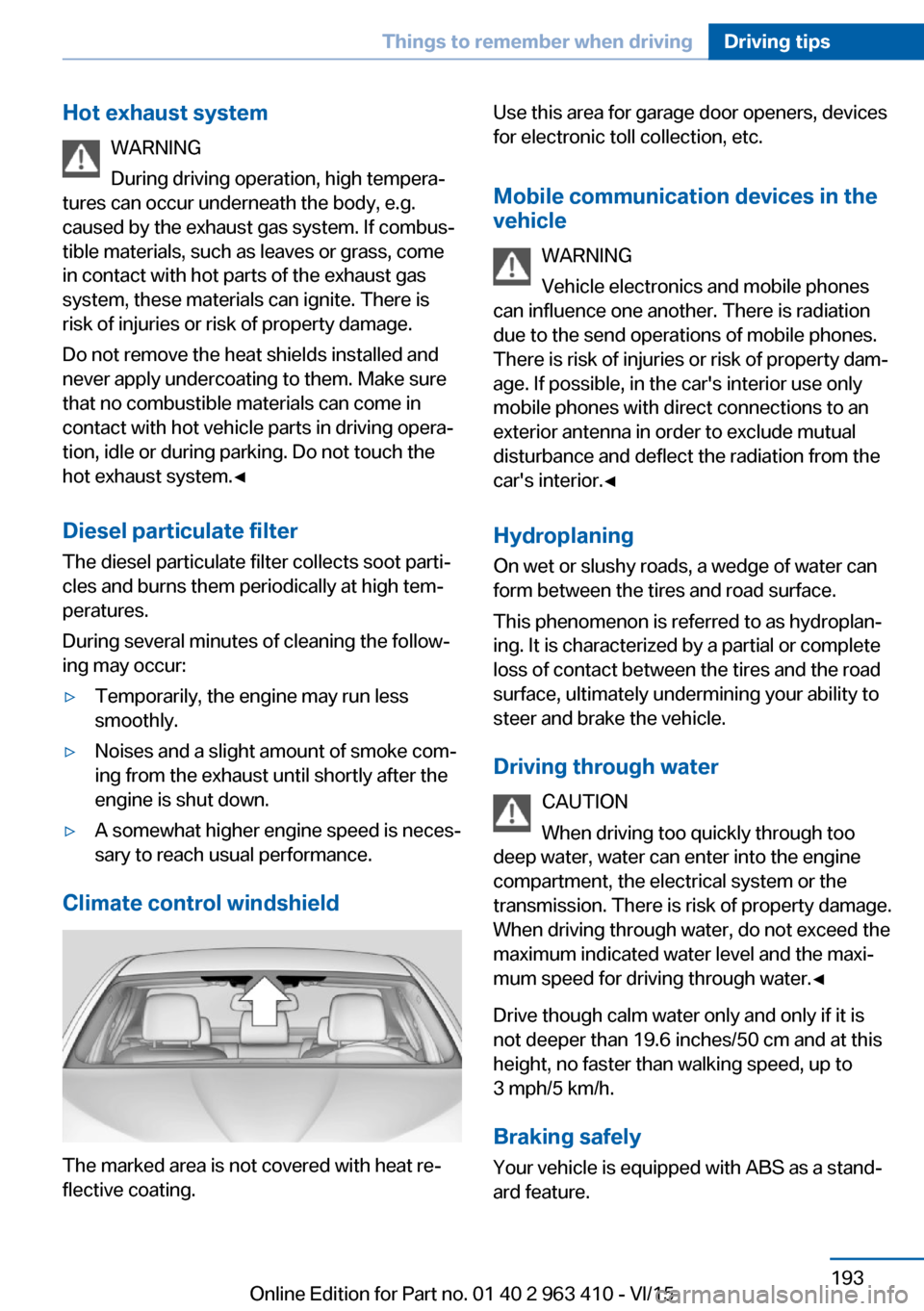
Climate control windshield
The marked area is not covered with heat re‐
flective coating.
Use this area for garage door openers, devices
for electronic toll collection, etc.
Mobile communication devices in the vehicle
WARNING
Vehicle electronics and mobile phones
can influence one another. There is radiation
due to the send operations of mobile phones.
There is risk of injuries or risk of property dam‐
age. If possible, in the car's interior use only
mobile phones with direct connections to an
exterior antenna in order to exclude mutual
disturbance and deflect the radiation from the
car's interior.◀
Hydroplaning
On wet or slushy roads, a wedge of water can
form between the tires and road surface.
This phenomenon is referred to as hydroplan‐
ing. It is characterized by a partial or complete
loss of contact between the tires and the road
surface, ultimately undermining your ability to
steer and brake the vehicle.
Driving through water CAUTION
When driving too quickly through too
deep water, water can enter into the engine
compartment, the electrical system or the
transmission. There is risk of property damage.
When driving through water, do not exceed the
maximum indicated water level and the maxi‐
mum speed for driving through water.◀
Drive though calm water only and only if it is
not deeper than 19.6 inches/50 cm and at this
height, no faster than walking speed, up to
3 mph/5 km/h.
Braking safely Your vehicle is equipped with ABS as a stand‐
ard feature.Seite 193Things to remember when drivingDriving tips193
Online Edition for Part no. 01 40 2 963 410 - VI/15
Page 212 of 275
To be able to start the engine as usual, there
must be an adequate Diesel exhaust fluid.
Warming up the system In order to warm the engine up to its operating
temperature after a cold start, the Steptronic
transmission may subsequently shift up to the
next higher gear.
Displays in the instrument cluster
Reserve indication
This display in the instrument cluster provides
information about the distance that can still be
driven with the current reserve level.
Do not continue driving to the limit of the re‐
maining travel distance. It is not possible to re‐
start the engine after switching it off.▷Lamp white: refill with Diesel
exhaust fluid at the next op‐
portunity.▷Lamp yellow: not enough
Diesel exhaust fluid present.
The remaining range is dis‐
played in the instrument
cluster. Immediately refill
with Diesel exhaust fluid, re‐
fer to page 212.
Diesel exhaust fluid on minimum
▷The remaining range is dis‐
played in the instrument
cluster: add Diesel exhaust
fluid. The engine will con‐
tinue to run as long as it is
not switched off and all
other operating conditions
are satisfied; sufficient fuel,
e.g.
System malfunction
A Check Control message is displayed when
there is a system not working.
Have the Diesel exhaust fluid
replenished
BMW recommends that the Diesel exhaust
fluid be added by the dealer’s service center
within the course of regular maintenance.
In addition it may be necessary to have the
fluid replenished several times under particular
circumstances, e.g., if the vehicle is driven in a
particularly sporty driving style or if it is driven
at high altitudes.
The Diesel exhaust fluid must be replenished
as soon as the reserve display appears in the
instrument cluster to avoid not being able to
restart the engine.
Diesel exhaust fluid at low
temperatures
Due to its physical properties, it is possible
that the Diesel exhaust fluid may also need to
be replenished between regular maintenance
appointments if it is exposed to temperatures
under + 23 ℉/- 5 ℃. In this case, add Diesel
exhaust fluid only immediately before driving
off.
At temperatures below + 12 ℉/- 11 ℃, the fill‐
ing level cannot be measured in some cases.
Replenishing Diesel exhaust fluid
yourself in exceptional cases
General information
You can replenish Diesel exhaust fluid yourself
in exceptional cases, e.g., to get to your sched‐
uled service.
Information WARNING
Small amounts of ammonia fumes can
escape when opening the Diesel exhaust fluid
container. Ammonia fumes have a pungent
odor and irritate skin, mucous membranes, and
eyes. There is risk of injuries. Do not inhale es‐
caping ammonia fumes. Avoid the contact of
articles of clothing, skin or eyes with Diesel ex‐Seite 212MobilityFuel212
Online Edition for Part no. 01 40 2 963 410 - VI/15
Page 214 of 275
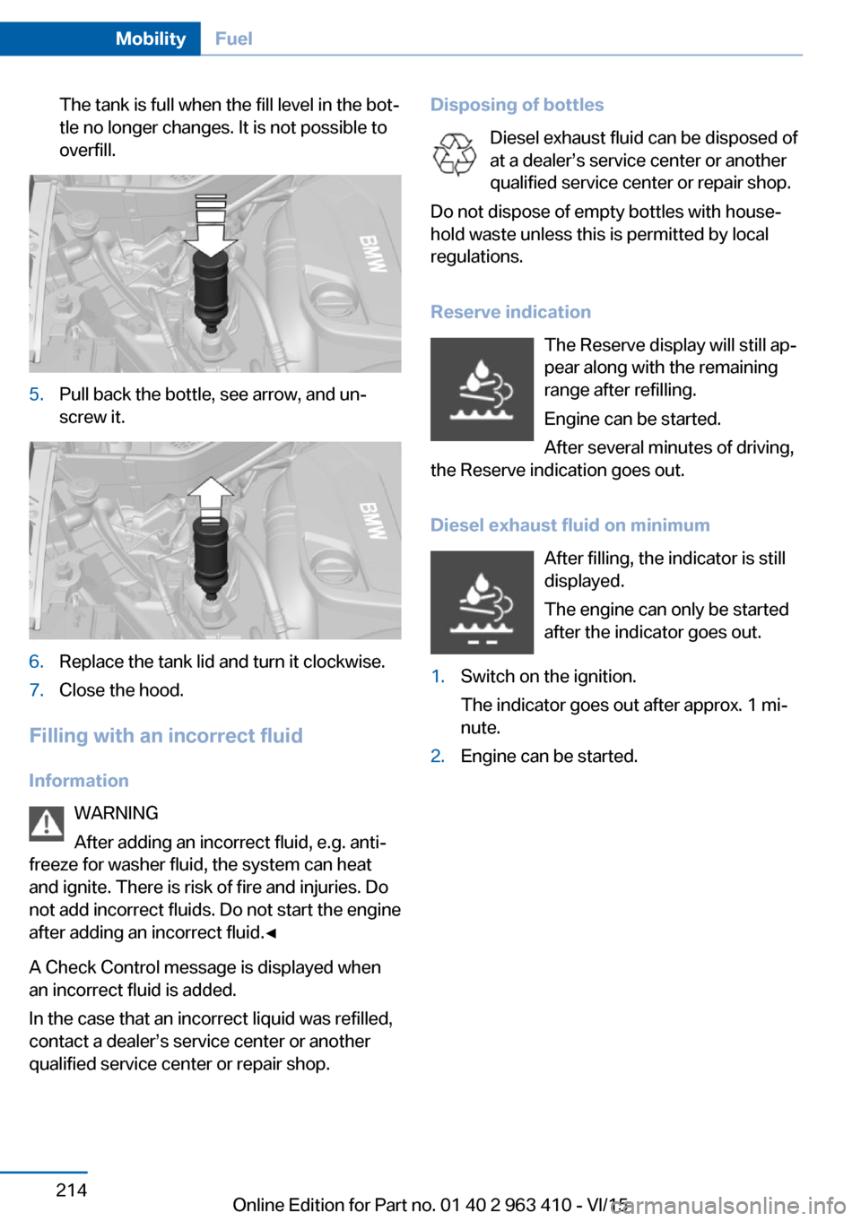
The tank is full when the fill level in the bot‐
tle no longer changes. It is not possible to
overfill.5.Pull back the bottle, see arrow, and un‐
screw it.6.Replace the tank lid and turn it clockwise.7.Close the hood.
Filling with an incorrect fluid
Information WARNING
After adding an incorrect fluid, e.g. anti‐
freeze for washer fluid, the system can heat
and ignite. There is risk of fire and injuries. Do
not add incorrect fluids. Do not start the engine
after adding an incorrect fluid.◀
A Check Control message is displayed when
an incorrect fluid is added.
In the case that an incorrect liquid was refilled,
contact a dealer’s service center or another
qualified service center or repair shop.
Disposing of bottles
Diesel exhaust fluid can be disposed of
at a dealer’s service center or another qualified service center or repair shop.
Do not dispose of empty bottles with house‐
hold waste unless this is permitted by local
regulations.
Reserve indication The Reserve display will still ap‐
pear along with the remaining
range after refilling.
Engine can be started.
After several minutes of driving,
the Reserve indication goes out.
Diesel exhaust fluid on minimum After filling, the indicator is still
displayed.
The engine can only be started
after the indicator goes out.1.Switch on the ignition.
The indicator goes out after approx. 1 mi‐
nute.2.Engine can be started.Seite 214MobilityFuel214
Online Edition for Part no. 01 40 2 963 410 - VI/15