Controls BMW X5 2015 F15 Workshop Manual
[x] Cancel search | Manufacturer: BMW, Model Year: 2015, Model line: X5, Model: BMW X5 2015 F15Pages: 275, PDF Size: 6.46 MB
Page 80 of 275
onds, until the wiper remains in a nearly
vertical position.
After the wipers are folded back down, the
wiper system must be reactivated.
1.Switch on the ignition.2.Push wiper lever down. Wipers move to
their resting position and are ready again
for operation.
Washer fluid
Information WARNING
Some antifreeze agents can contain
harmful substances and are flammable. There
is risk of fire and risk of injuries. Observe the
instructions on the containers. Keep antifreeze
away from ignition sources. Do not refill oper‐
ating materials into different bottles. Store op‐
erating materials out of reach of children.
United States: The washer fluid mixture ratio is
regulated by the U.S. EPA and many individual
states; do not exceed the allowable washer
fluid dilution ratio limits that apply. Follow the
usage instructions on the washer fluid con‐
tainer.
Use of BMW’s Windshield Washer Concen‐
trate or the equivalent is recommended.◀
WARNING
Improperly executed work under the
hood can damage components and lead to a
safety risk. There is risk of accidents or risk of
property damage. Have work under the hood
be executed by a dealer’s service center or an‐
other qualified service center or repair shop.◀
Washer fluid reservoir
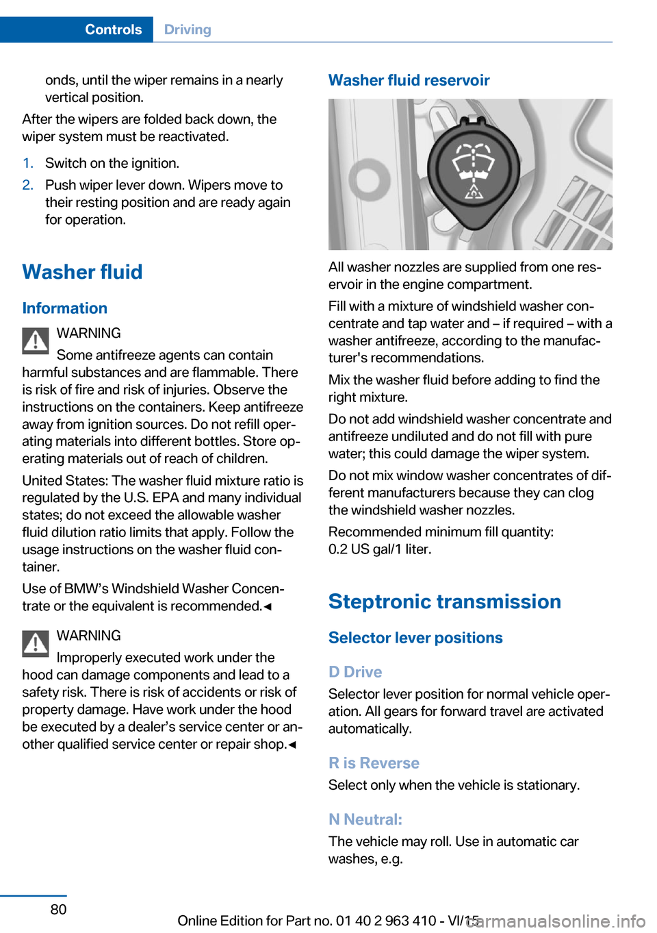
All washer nozzles are supplied from one res‐
ervoir in the engine compartment.
Fill with a mixture of windshield washer con‐
centrate and tap water and – if required – with a
washer antifreeze, according to the manufac‐
turer's recommendations.
Mix the washer fluid before adding to find the
right mixture.
Do not add windshield washer concentrate and
antifreeze undiluted and do not fill with pure
water; this could damage the wiper system.
Do not mix window washer concentrates of dif‐
ferent manufacturers because they can clog
the windshield washer nozzles.
Recommended minimum fill quantity:
0.2 US gal/1 liter.
Steptronic transmission
Selector lever positions
D Drive
Selector lever position for normal vehicle oper‐
ation. All gears for forward travel are activated
automatically.
R is Reverse
Select only when the vehicle is stationary.
N Neutral: The vehicle may roll. Use in automatic car
washes, e.g.
Seite 80ControlsDriving80
Online Edition for Part no. 01 40 2 963 410 - VI/15
Page 81 of 275
When the ignition is switched off, refer to
page 69, selector lever position P is engaged
automatically.
P Park Select only when the vehicle is stationary. The
drive wheels are blocked.
P is engaged automatically:▷After the engine is switched off when the
vehicle is in radio-ready state, refer to
page 69, or when the ignition is switched
off, refer to page 69, and when selector
lever position R or D is set.▷With the ignition off, if selector lever posi‐
tion N is set.▷If the driver's safety belt is released, the
driver's door is opened, and the brake
pedal is not pressed while the vehicle is
stationary and selector lever position D or
R is set.
Before exiting the vehicle, make sure that se‐
lector lever position P is set. Otherwise, the ve‐
hicle may begin to move.
Kickdown Kickdown is used to achieve maximum driving
performance. Step on the accelerator pedal
beyond the resistance point at the full throttle
position.
Engaging selector lever positions
General information To prevent the vehicle from creeping after you
select a gear, maintain pressure on the brake
pedal until you are ready to start.
▷It is not possible to shift out of selector
lever position P until the engine is running
and the brake is applied.▷With the vehicle is stationary, press on the
brake pedal before shifting out of selector
lever position P or N; otherwise, the shift
command will not be executed: shift lock.A block prevents the inadvertent switching to
selector lever position P or R or the inadvertent
change from selector lever position P.
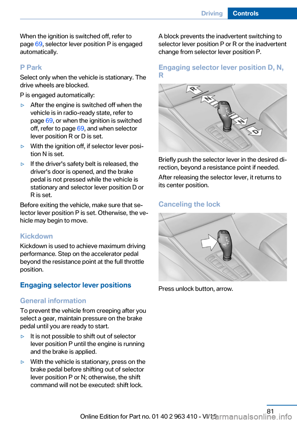
Engaging selector lever position D, N,
R
Briefly push the selector lever in the desired di‐
rection, beyond a resistance point if needed.
After releasing the selector lever, it returns to
its center position.
Canceling the lock
Press unlock button, arrow.
Seite 81DrivingControls81
Online Edition for Part no. 01 40 2 963 410 - VI/15
Page 82 of 275
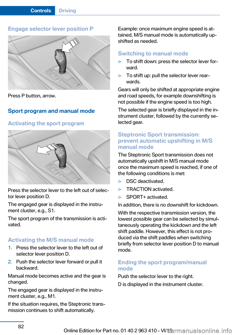
Engage selector lever position P
Press P button, arrow.
Sport program and manual mode
Activating the sport program
Press the selector lever to the left out of selec‐
tor lever position D.
The engaged gear is displayed in the instru‐
ment cluster, e.g., S1.
The sport program of the transmission is acti‐
vated.
Activating the M/S manual mode
1.Press the selector lever to the left out of
selector lever position D.2.Push the selector lever forward or pull it
backward.
Manual mode becomes active and the gear is
changed.
The engaged gear is displayed in the instru‐
ment cluster, e.g., M1.
If the situation requires, the Steptronic trans‐
mission continues to shift automatically.
Example: once maximum engine speed is at‐
tained, M/S manual mode is automatically up‐
shifted as needed.
Switching to manual mode▷To shift down: press the selector lever for‐
ward.▷To shift up: pull the selector lever rear‐
wards.
Gears will only be shifted at appropriate engine
and road speeds, for example downshifting is
not possible if the engine speed is too high.
The selected gear is briefly displayed in the in‐
strument cluster, followed by the currently se‐
lected gear.
Steptronic Sport transmission:
prevent automatic upshifting in M/S
manual mode
The Steptronic Sport transmission does not
automatically upshift in M/S manual mode
once the maximum speed is reached, if one of
the following conditions is met:
▷DSC deactivated.▷TRACTION activated.▷SPORT+ activated.
In addition, there is no downshift for kickdown.
With the respective transmission version, the
lowest possible gear can be selected by simul‐
taneously operating the kickdown and the left
shift paddle. However, this effect is not pro‐
duced via the shift paddles when switching
briefly from selector lever position D to manual
mode.
Ending the sport program/manual
mode
Push the selector lever to the right.
D is displayed in the instrument cluster.
Seite 82ControlsDriving82
Online Edition for Part no. 01 40 2 963 410 - VI/15
Page 83 of 275
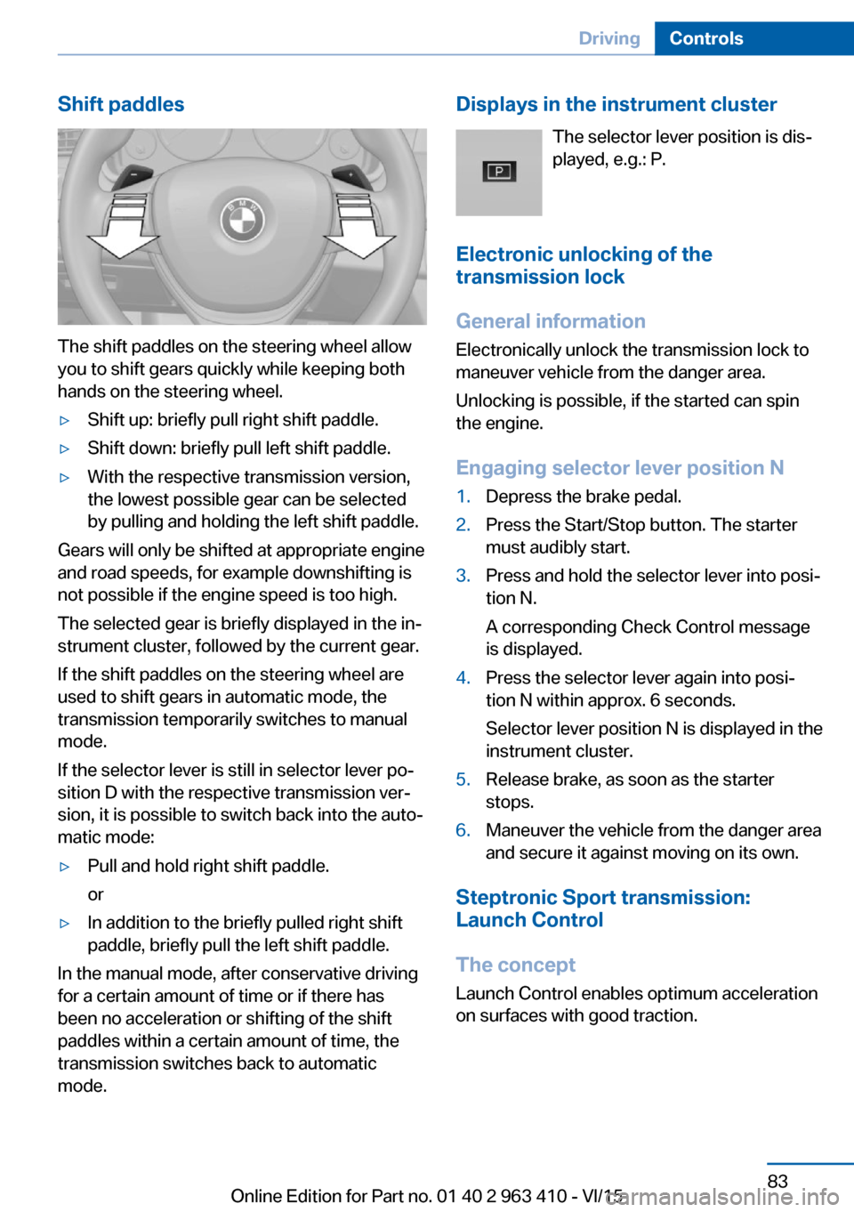
Shift paddles
The shift paddles on the steering wheel allow
you to shift gears quickly while keeping both
hands on the steering wheel.
▷Shift up: briefly pull right shift paddle.▷Shift down: briefly pull left shift paddle.▷With the respective transmission version,
the lowest possible gear can be selected
by pulling and holding the left shift paddle.
Gears will only be shifted at appropriate engine
and road speeds, for example downshifting is
not possible if the engine speed is too high.
The selected gear is briefly displayed in the in‐
strument cluster, followed by the current gear.
If the shift paddles on the steering wheel are
used to shift gears in automatic mode, the
transmission temporarily switches to manual
mode.
If the selector lever is still in selector lever po‐
sition D with the respective transmission ver‐
sion, it is possible to switch back into the auto‐
matic mode:
▷Pull and hold right shift paddle.
or▷In addition to the briefly pulled right shift
paddle, briefly pull the left shift paddle.
In the manual mode, after conservative driving
for a certain amount of time or if there has
been no acceleration or shifting of the shift
paddles within a certain amount of time, the
transmission switches back to automatic
mode.
Displays in the instrument cluster
The selector lever position is dis‐played, e.g.: P.
Electronic unlocking of the
transmission lock
General information
Electronically unlock the transmission lock to
maneuver vehicle from the danger area.
Unlocking is possible, if the started can spin
the engine.
Engaging selector lever position N1.Depress the brake pedal.2.Press the Start/Stop button. The starter
must audibly start.3.Press and hold the selector lever into posi‐
tion N.
A corresponding Check Control message
is displayed.4.Press the selector lever again into posi‐
tion N within approx. 6 seconds.
Selector lever position N is displayed in the
instrument cluster.5.Release brake, as soon as the starter
stops.6.Maneuver the vehicle from the danger area
and secure it against moving on its own.
Steptronic Sport transmission:
Launch Control
The concept Launch Control enables optimum accelerationon surfaces with good traction.
Seite 83DrivingControls83
Online Edition for Part no. 01 40 2 963 410 - VI/15
Page 84 of 275
General information
The use of Launch Control causes premature
component wear since this function represents
a very heavy load for the vehicle.
Do not use Launch Control during the break-in,
refer to page 192, period.
To increase vehicle stability, activate DSC again as soon as possible.
An experienced driver may be able to achieve
better acceleration values in DSC OFF mode.
Requirements
Launch Control is available when the engine is
warmed up, that is, after uninterrupted driving
of at least 6 miles/10 km.
To start with Launch Control do not steer the
steering wheel.
Start with launch controlWhile the engine is running:1. Press button or select Sport+ with
the Driving Dynamics Control.
TRACTION is displayed in the instrument
cluster and the indicator lamp for DSC OFF
lights up.2.Engage selector lever position S.3.With the left foot, forcefully press down on
the brake.4.Press and hold down the accelerator pedal
beyond the resistance point at the full
throttle position, kickdown.
A flag symbol is displayed in the instru‐
ment cluster.5.The starting engine speed adjusts. Within
3 seconds, release the brake.
Before using Launch Control, allow the trans‐
mission to cool down for approx. 5 minutes.
Launch Control adjusts to the surrounding
conditions, e.g., wet pavement, when used
again.
Seite 84ControlsDriving84
Online Edition for Part no. 01 40 2 963 410 - VI/15
Page 85 of 275
DisplaysVehicle features and optionsThis chapter describes all standard, country-
specific and optional features offered with the
series. It also describes features that are not
necessarily available in your car, e. g., due tothe selected options or country versions. This
also applies to safety-related functions and
systems. The respectively applicable country
provisions must be observed when using the
respective features and systems.
Overview, instrument cluster
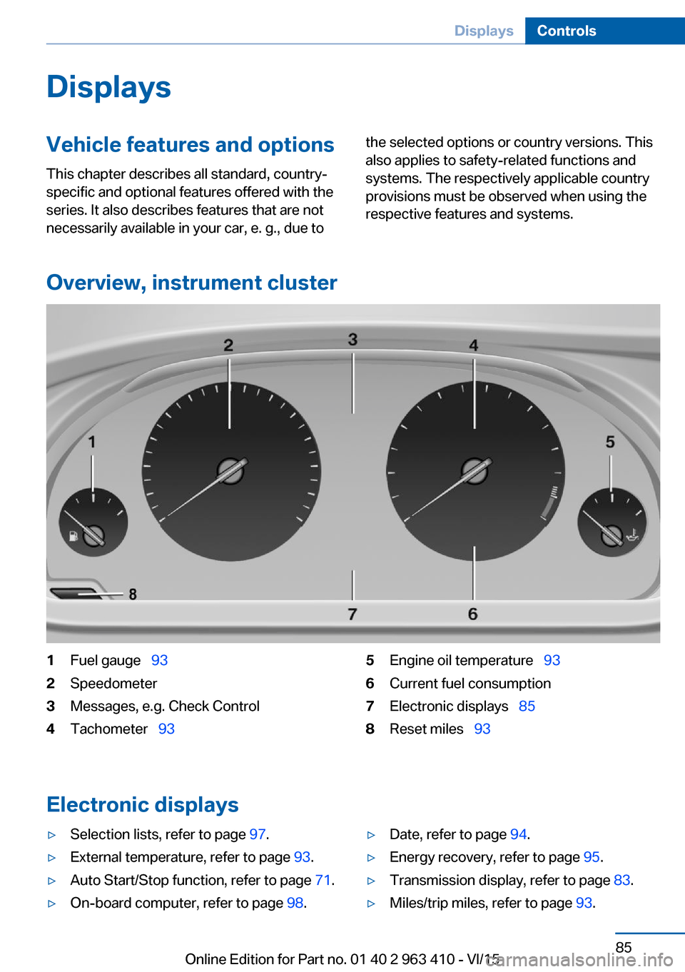
1Fuel gauge 932Speedometer3Messages, e.g. Check Control4Tachometer 935Engine oil temperature 936Current fuel consumption7Electronic displays 858Reset miles 93
Electronic displays
▷Selection lists, refer to page 97.▷External temperature, refer to page 93.▷Auto Start/Stop function, refer to page 71.▷On-board computer, refer to page 98.▷Date, refer to page 94.▷Energy recovery, refer to page 95.▷Transmission display, refer to page 83.▷Miles/trip miles, refer to page 93.Seite 85DisplaysControls85
Online Edition for Part no. 01 40 2 963 410 - VI/15
Page 86 of 275
▷Messages, e.g. Check Control, refer to
page 89.▷Current fuel consumption, refer to
page 94.▷Navigation display, see User's manual for
Navigation, Entertainment and Communi‐
cation.▷Range, refer to page 94.▷Status, Driving Dynamics Control, refer to
page 142.▷Service requirements, refer to page 95.▷Speed limit detection, refer to page 96.▷Time, refer to page 94.
Multifunctional instrument display
The concept
The instrument display is a variable display. In
the event of a program change, the display
rendition adapts to the respective program
through the Driving Dynamics Control. The
change of the display type can be deactivated
via iDrive.Some of the displays in the instrument display
may differ from the way they are shown in this
Owner's Manual.
Overview
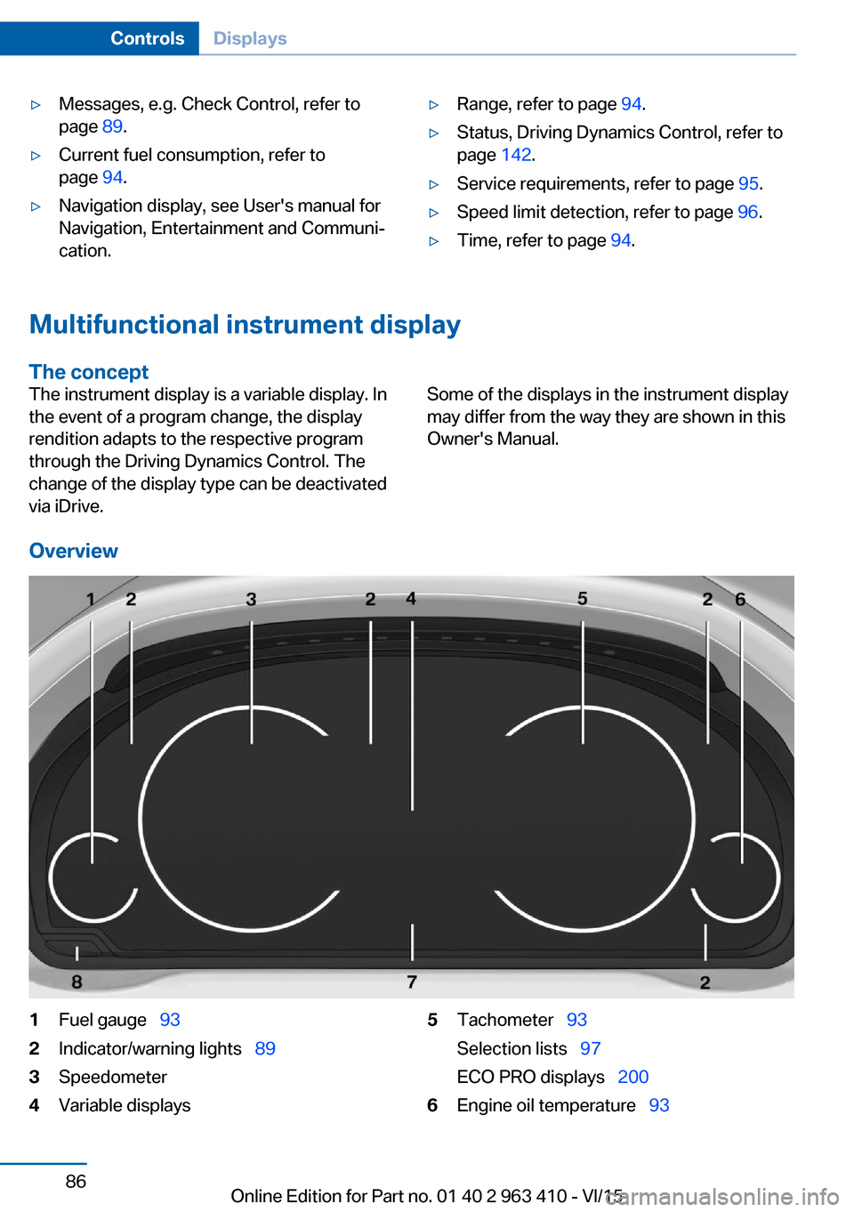
1Fuel gauge 932Indicator/warning lights 893Speedometer4Variable displays5Tachometer 93
Selection lists 97
ECO PRO displays 2006Engine oil temperature 93Seite 86ControlsDisplays86
Online Edition for Part no. 01 40 2 963 410 - VI/15
Page 87 of 275
7On-board computer 988Reset miles 93Switching the change of display on
and off
You can set whether the instrument display
automatically changes to the ECO PRO or
SPORT in the display when you switch driving
modes.
On the Control Display:1."Settings"2."Instrument cluster"3."ECO PRO Info"Or "Driving mode view"
With Professional Navigation System:
switching zoom function on/off
You can program whether the current speed is
to appear enlarged in the speedometer.
On the Control Display:
1."Settings"2."Instrument cluster"3."Magnifier function"
ECO PRO displays
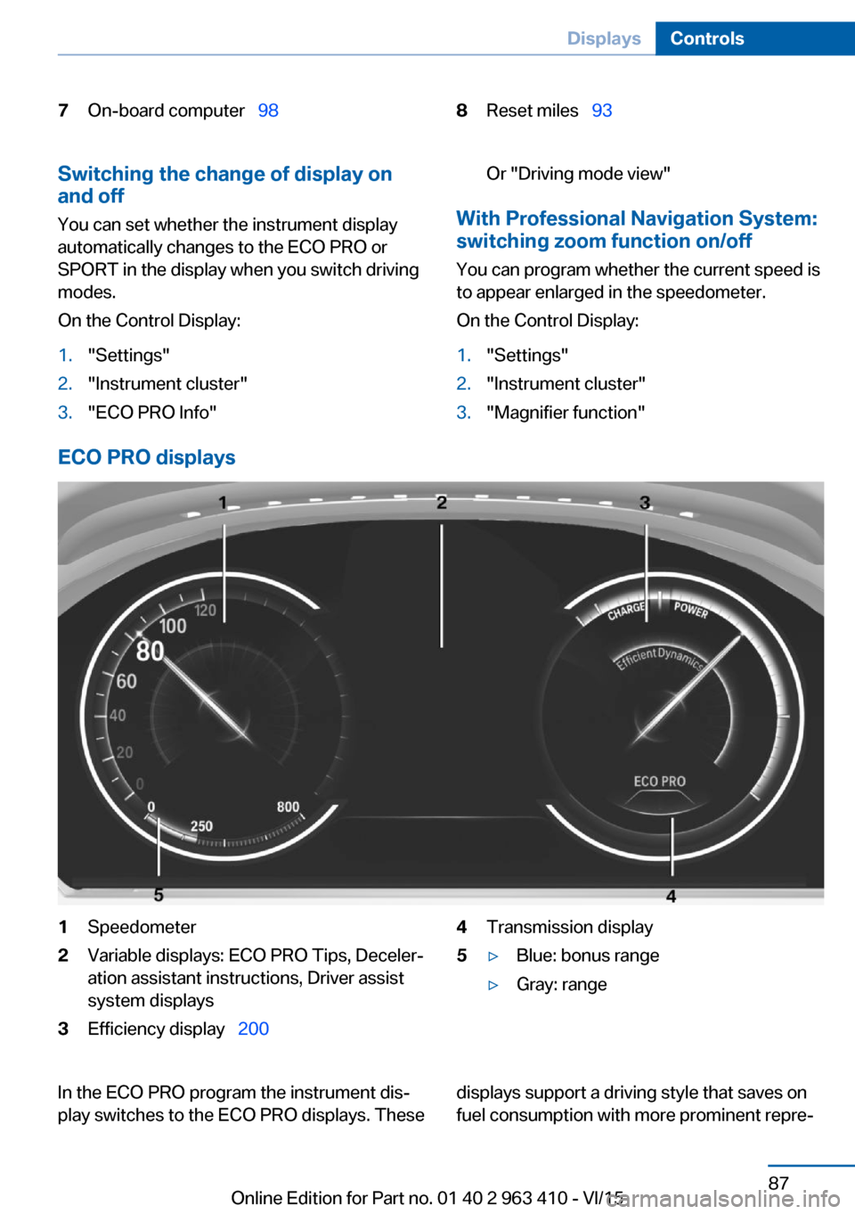
1Speedometer2Variable displays: ECO PRO Tips, Deceler‐
ation assistant instructions, Driver assist
system displays3Efficiency display 2004Transmission display5▷Blue: bonus range▷Gray: rangeIn the ECO PRO program the instrument dis‐
play switches to the ECO PRO displays. Thesedisplays support a driving style that saves on
fuel consumption with more prominent repre‐Seite 87DisplaysControls87
Online Edition for Part no. 01 40 2 963 410 - VI/15
Page 88 of 275
sentation of the efficiency display and various
ECO PRO tips.
Sport displays
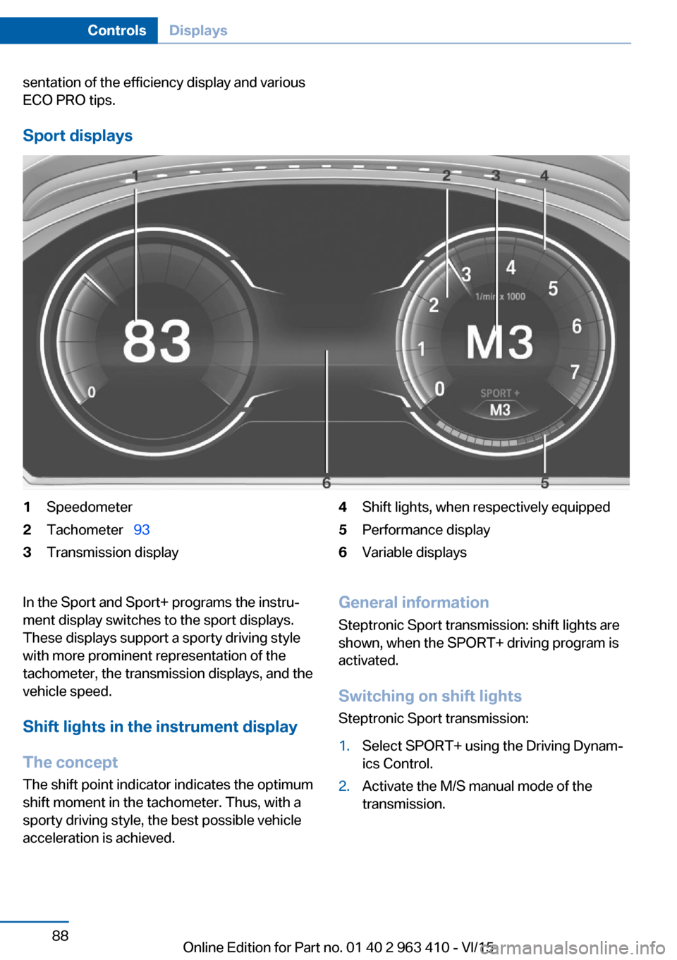
1Speedometer2Tachometer 933Transmission display4Shift lights, when respectively equipped5Performance display6Variable displaysIn the Sport and Sport+ programs the instru‐
ment display switches to the sport displays.
These displays support a sporty driving style
with more prominent representation of the
tachometer, the transmission displays, and the
vehicle speed.
Shift lights in the instrument display
The concept The shift point indicator indicates the optimum
shift moment in the tachometer. Thus, with a
sporty driving style, the best possible vehicle
acceleration is achieved.General information
Steptronic Sport transmission: shift lights are
shown, when the SPORT+ driving program is
activated.
Switching on shift lights Steptronic Sport transmission:1.Select SPORT+ using the Driving Dynam‐
ics Control.2.Activate the M/S manual mode of the
transmission.Seite 88ControlsDisplays88
Online Edition for Part no. 01 40 2 963 410 - VI/15
Page 89 of 275
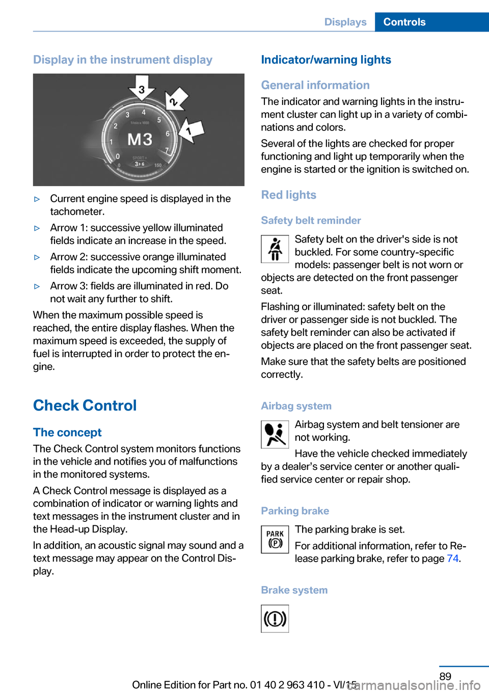
Display in the instrument display▷Current engine speed is displayed in the
tachometer.▷Arrow 1: successive yellow illuminated
fields indicate an increase in the speed.▷Arrow 2: successive orange illuminated
fields indicate the upcoming shift moment.▷Arrow 3: fields are illuminated in red. Do
not wait any further to shift.
When the maximum possible speed is
reached, the entire display flashes. When the
maximum speed is exceeded, the supply of
fuel is interrupted in order to protect the en‐
gine.
Check Control The conceptThe Check Control system monitors functions
in the vehicle and notifies you of malfunctions
in the monitored systems.
A Check Control message is displayed as a
combination of indicator or warning lights and
text messages in the instrument cluster and in
the Head-up Display.
In addition, an acoustic signal may sound and a
text message may appear on the Control Dis‐
play.
Indicator/warning lights
General information
The indicator and warning lights in the instru‐
ment cluster can light up in a variety of combi‐
nations and colors.
Several of the lights are checked for proper
functioning and light up temporarily when the
engine is started or the ignition is switched on.
Red lights
Safety belt reminder Safety belt on the driver's side is not
buckled. For some country-specific
models: passenger belt is not worn or
objects are detected on the front passenger
seat.
Flashing or illuminated: safety belt on the
driver or passenger side is not buckled. The
safety belt reminder can also be activated if
objects are placed on the front passenger seat.
Make sure that the safety belts are positioned
correctly.
Airbag system Airbag system and belt tensioner are
not working.
Have the vehicle checked immediately
by a dealer’s service center or another quali‐
fied service center or repair shop.
Parking brake The parking brake is set.
For additional information, refer to Re‐
lease parking brake, refer to page 74.
Brake systemSeite 89DisplaysControls89
Online Edition for Part no. 01 40 2 963 410 - VI/15