brake service light BMW X5 2015 F15 Owner's Manual
[x] Cancel search | Manufacturer: BMW, Model Year: 2015, Model line: X5, Model: BMW X5 2015 F15Pages: 275, PDF Size: 6.46 MB
Page 9 of 275
▷Operating mode of system components, fill
levels for instance.▷Status messages for the vehicle and from
its individual components, e.g., wheel rota‐
tion speed/vehicle speed, deceleration,
transverse acceleration.▷Malfunctions and faults in important sys‐
tem components, e.g., lights and brakes.▷Responses by the vehicle to special situa‐
tions such as airbag deployment or engag‐
ing the stability control system.▷Ambient conditions, such as temperature.
This data is purely technical in nature and is
used to detect and correct faults and to opti‐
mize vehicle functions. Motion profiles over
routes traveled cannot be created from this
data. When service offerings are used, e.g., re‐
pair services, service processes, warranty
claims, quality assurance, this technical infor‐
mation can be read out from the event and
fault memories by employees of the dealer’s
service center or another qualified service cen‐
ter or repair shop, including the manufacturer,
using special diagnostic tools. You can obtain
further information there if you need it. After an
error is corrected, the information in the fault
memory is deleted or overwritten on a continu‐
ous basis.
With the vehicle in use there are situations
where you can associate these technical data
with individuals if combined with other infor‐
mation, e.g., an accident report, damage to the
vehicle, eye witness accounts — possibly with
the assistance of an expert.
Additional functions that are contractually
agreed with the customer - such as vehicle
emergency locating - you can transmit certain
vehicle data from the vehicle.
Event Data Recorder EDR
This vehicle is equipped with an event data re‐
corder EDR. The main purpose of an EDR is to
record, in certain crash or near crash-like situa‐
tions, such as an air bag deployment or hitting
a road obstacle, data that will assist in under‐
standing how a vehicle’s systems performed.
The EDR is designed to record data related to
vehicle dynamics and safety systems for a
short period of time, typically 30 seconds or
less.
The EDR in this vehicle is designed to record
such data as:▷How various systems in your vehicle were
operating.▷Whether or not the driver and passenger
safety belts were fastened.▷How far, if at all, the driver was depressing
the accelerator and/or brake pedal.▷How fast the vehicle was traveling.
These data can help provide a better under‐
standing of the circumstances in which
crashes and injuries occur.
EDR data are recorded by your vehicle only if a
nontrivial crash situation occurs; no data are
recorded by the EDR under normal driving
conditions and no personal data, e.g., name,
gender, age, and crash location, are recorded.
However, other parties, such as law enforce‐
ment, could combine the EDR data with the
type of personally identifying data routinely ac‐
quired during a crash investigation.
To read data recorded by an EDR, special
equipment is required, and access to the vehi‐
cle or the EDR is needed. In addition to the ve‐
hicle manufacturer, other parties, such as law
enforcement, that have the special equipment,
can read the information if they have access to
the vehicle or the EDR.
Seite 9Information9
Online Edition for Part no. 01 40 2 963 410 - VI/15
Page 35 of 275
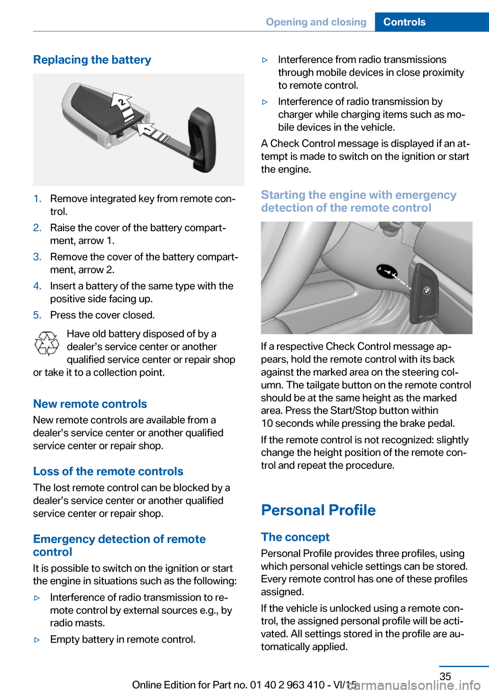
Replacing the battery1.Remove integrated key from remote con‐
trol.2.Raise the cover of the battery compart‐
ment, arrow 1.3.Remove the cover of the battery compart‐
ment, arrow 2.4.Insert a battery of the same type with the
positive side facing up.5.Press the cover closed.
Have old battery disposed of by a
dealer’s service center or another
qualified service center or repair shop
or take it to a collection point.
New remote controlsNew remote controls are available from a
dealer’s service center or another qualified
service center or repair shop.
Loss of the remote controls
The lost remote control can be blocked by a
dealer’s service center or another qualified
service center or repair shop.
Emergency detection of remote
control
It is possible to switch on the ignition or start
the engine in situations such as the following:
▷Interference of radio transmission to re‐
mote control by external sources e.g., by
radio masts.▷Empty battery in remote control.▷Interference from radio transmissions
through mobile devices in close proximity
to remote control.▷Interference of radio transmission by
charger while charging items such as mo‐
bile devices in the vehicle.
A Check Control message is displayed if an at‐
tempt is made to switch on the ignition or start
the engine.
Starting the engine with emergency
detection of the remote control
If a respective Check Control message ap‐
pears, hold the remote control with its back
against the marked area on the steering col‐
umn. The tailgate button on the remote control
should be at the same height as the marked
area. Press the Start/Stop button within
10 seconds while pressing the brake pedal.
If the remote control is not recognized: slightly
change the height position of the remote con‐
trol and repeat the procedure.
Personal Profile
The concept Personal Profile provides three profiles, using
which personal vehicle settings can be stored.
Every remote control has one of these profiles
assigned.
If the vehicle is unlocked using a remote con‐
trol, the assigned personal profile will be acti‐
vated. All settings stored in the profile are au‐
tomatically applied.
Seite 35Opening and closingControls35
Online Edition for Part no. 01 40 2 963 410 - VI/15
Page 58 of 275
Buckling the belt
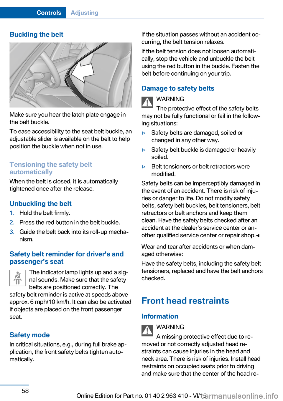
Make sure you hear the latch plate engage in
the belt buckle.
To ease accessibility to the seat belt buckle, an
adjustable slider is available on the belt to help
position the buckle when not in use.
Tensioning the safety belt
automatically
When the belt is closed, it is automatically
tightened once after the release.
Unbuckling the belt
1.Hold the belt firmly.2.Press the red button in the belt buckle.3.Guide the belt back into its roll-up mecha‐
nism.
Safety belt reminder for driver's and
passenger's seat
The indicator lamp lights up and a sig‐
nal sounds. Make sure that the safety
belts are positioned correctly. The
safety belt reminder is active at speeds above
approx. 6 mph/10 km/h. It can also be activated
if objects are placed on the front passenger
seat.
Safety mode In critical situations, e.g., during full brake ap‐
plication, the front safety belts tighten auto‐
matically.
If the situation passes without an accident oc‐
curring, the belt tension relaxes.
If the belt tension does not loosen automati‐
cally, stop the vehicle and unbuckle the belt
using the red button in the buckle. Fasten the
belt before continuing on your trip.
Damage to safety belts WARNING
The protective effect of the safety belts
may not be fully functional or fail in the follow‐
ing situations:▷Safety belts are damaged, soiled or
changed in any other way.▷Safety belt buckle is damaged or heavily
soiled.▷Belt tensioners or belt retractors were
modified.
Safety belts can be imperceptibly damaged in
the event of an accident. There is risk of inju‐
ries or danger to life. Do not modify safety
belts, safety belt buckles, belt tensioners, belt
retractors or belt anchors and keep them
clean. Have the safety belts checked after an
accident at the dealer’s service center or an‐
other qualified service center or repair shop.◀
Wear and tear after accidents or when dam‐
aged otherwise:
Have the safety belts, including the safety belt
tensioners, replaced and have the belt anchors
checked.
Front head restraints Information WARNING
A missing protective effect due to re‐
moved or not correctly adjusted head re‐
straints can cause injuries in the head and
neck area. There is risk of injuries. Install head
restraints on occupied seats prior to driving
and make sure that the center of the head re‐
Seite 58ControlsAdjusting58
Online Edition for Part no. 01 40 2 963 410 - VI/15
Page 89 of 275
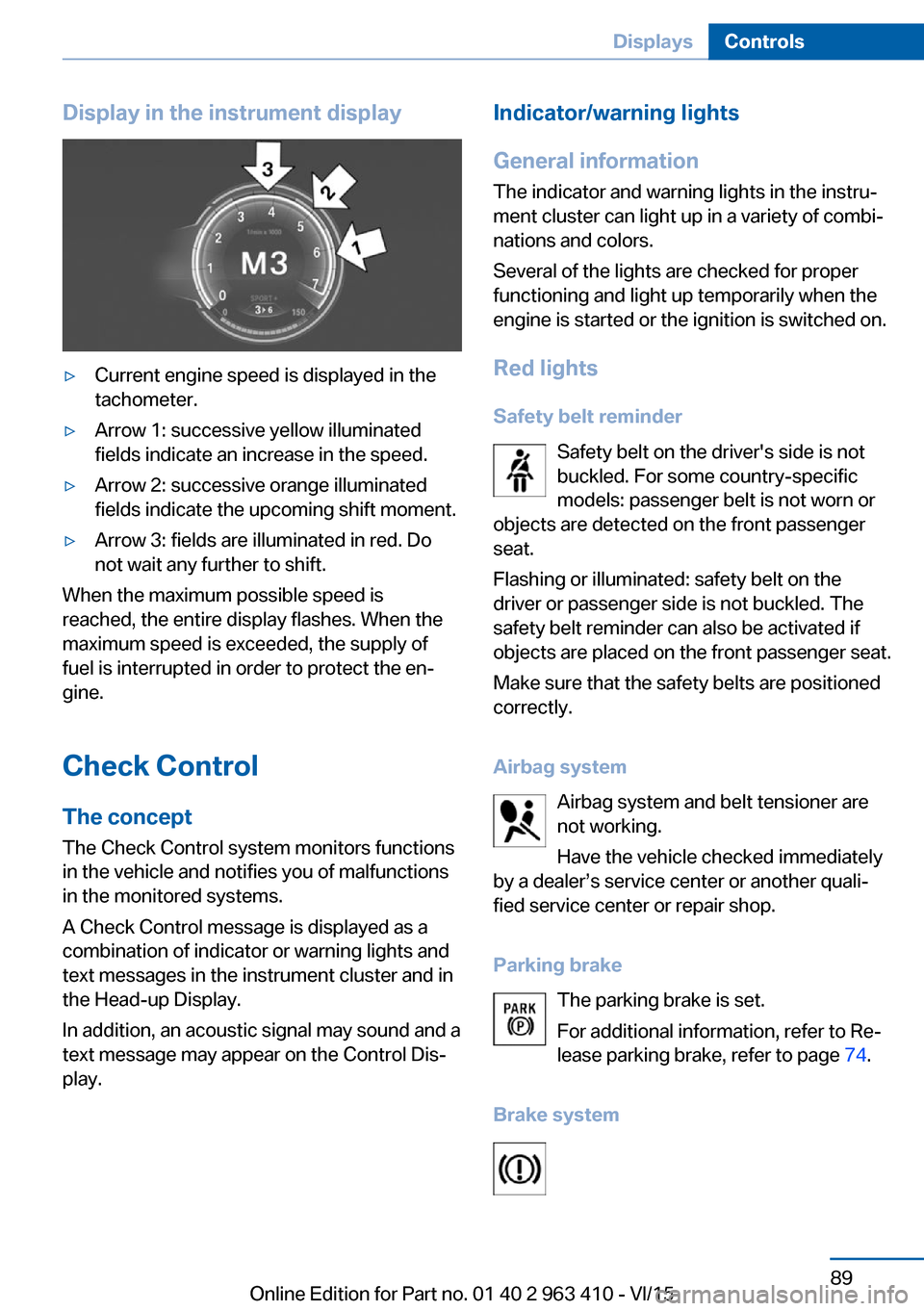
Display in the instrument display▷Current engine speed is displayed in the
tachometer.▷Arrow 1: successive yellow illuminated
fields indicate an increase in the speed.▷Arrow 2: successive orange illuminated
fields indicate the upcoming shift moment.▷Arrow 3: fields are illuminated in red. Do
not wait any further to shift.
When the maximum possible speed is
reached, the entire display flashes. When the
maximum speed is exceeded, the supply of
fuel is interrupted in order to protect the en‐
gine.
Check Control The conceptThe Check Control system monitors functions
in the vehicle and notifies you of malfunctions
in the monitored systems.
A Check Control message is displayed as a
combination of indicator or warning lights and
text messages in the instrument cluster and in
the Head-up Display.
In addition, an acoustic signal may sound and a
text message may appear on the Control Dis‐
play.
Indicator/warning lights
General information
The indicator and warning lights in the instru‐
ment cluster can light up in a variety of combi‐
nations and colors.
Several of the lights are checked for proper
functioning and light up temporarily when the
engine is started or the ignition is switched on.
Red lights
Safety belt reminder Safety belt on the driver's side is not
buckled. For some country-specific
models: passenger belt is not worn or
objects are detected on the front passenger
seat.
Flashing or illuminated: safety belt on the
driver or passenger side is not buckled. The
safety belt reminder can also be activated if
objects are placed on the front passenger seat.
Make sure that the safety belts are positioned
correctly.
Airbag system Airbag system and belt tensioner are
not working.
Have the vehicle checked immediately
by a dealer’s service center or another quali‐
fied service center or repair shop.
Parking brake The parking brake is set.
For additional information, refer to Re‐
lease parking brake, refer to page 74.
Brake systemSeite 89DisplaysControls89
Online Edition for Part no. 01 40 2 963 410 - VI/15
Page 90 of 275
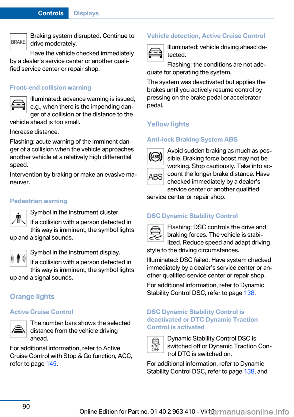
Braking system disrupted. Continue to
drive moderately.
Have the vehicle checked immediately
by a dealer’s service center or another quali‐
fied service center or repair shop.
Front-end collision warning Illuminated: advance warning is issued,
e.g., when there is the impending dan‐
ger of a collision or the distance to the
vehicle ahead is too small.
Increase distance.
Flashing: acute warning of the imminent dan‐
ger of a collision when the vehicle approaches
another vehicle at a relatively high differential
speed.
Intervention by braking or make an evasive ma‐
neuver.
Pedestrian warning Symbol in the instrument cluster.
If a collision with a person detected in
this way is imminent, the symbol lights
up and a signal sounds.
Symbol in the instrument display.
If a collision with a person detected in
this way is imminent, the symbol lights
up and a signal sounds.
Orange lights
Active Cruise Control The number bars shows the selected
distance from the vehicle driving
ahead.
For additional information, refer to Active
Cruise Control with Stop & Go function, ACC,
refer to page 145.Vehicle detection, Active Cruise Control
Illuminated: vehicle driving ahead de‐tected.
Flashing: the conditions are not ade‐
quate for operating the system.
The system was deactivated but applies the
brakes until you actively resume control by
pressing on the brake pedal or accelerator
pedal.
Yellow lights
Anti-lock Braking System ABS Avoid sudden braking as much as pos‐
sible. Braking force boost may not be
working. Stop cautiously. Take into ac‐
count the longer brake distance. Have
checked immediately by a dealer’s
service center or another qualified
service center or repair shop.
DSC Dynamic Stability Control Flashing: DSC controls the drive and
braking forces. The vehicle is stabi‐
lized. Reduce speed and adapt driving
style to the driving circumstances.
Illuminated: DSC failed. Have system checked
immediately by a dealer’s service center or an‐
other qualified service center or repair shop.
For additional information, refer to Dynamic
Stability Control DSC, refer to page 138.
DSC Dynamic Stability Control is
deactivated or DTC Dynamic Traction
Control is activated
Dynamic Stability Control DSC is
switched off or Dynamic Traction Con‐
trol DTC is switched on.
For additional information, refer to Dynamic
Stability Control DSC, refer to page 138, andSeite 90ControlsDisplays90
Online Edition for Part no. 01 40 2 963 410 - VI/15
Page 244 of 275
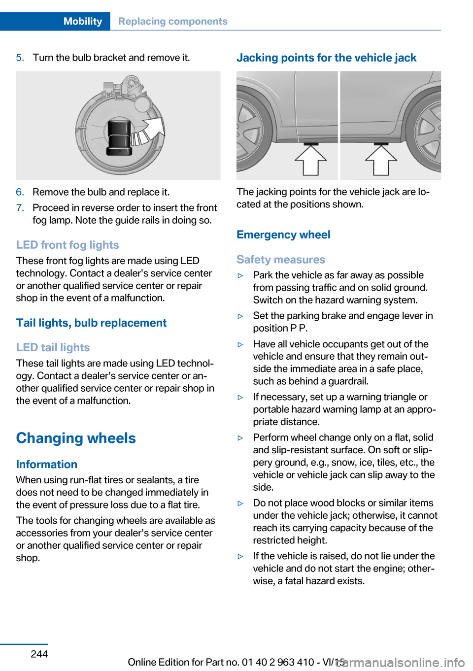
5.Turn the bulb bracket and remove it.6.Remove the bulb and replace it.7.Proceed in reverse order to insert the front
fog lamp. Note the guide rails in doing so.
LED front fog lights
These front fog lights are made using LED
technology. Contact a dealer’s service center
or another qualified service center or repair
shop in the event of a malfunction.
Tail lights, bulb replacement
LED tail lights
These tail lights are made using LED technol‐
ogy. Contact a dealer’s service center or an‐
other qualified service center or repair shop in
the event of a malfunction.
Changing wheels
Information When using run-flat tires or sealants, a tire
does not need to be changed immediately in
the event of pressure loss due to a flat tire.
The tools for changing wheels are available as
accessories from your dealer’s service center
or another qualified service center or repair
shop.
Jacking points for the vehicle jack
The jacking points for the vehicle jack are lo‐
cated at the positions shown.
Emergency wheel
Safety measures
▷Park the vehicle as far away as possible
from passing traffic and on solid ground.
Switch on the hazard warning system.▷Set the parking brake and engage lever in
position P P.▷Have all vehicle occupants get out of the
vehicle and ensure that they remain out‐
side the immediate area in a safe place,
such as behind a guardrail.▷If necessary, set up a warning triangle or
portable hazard warning lamp at an appro‐
priate distance.▷Perform wheel change only on a flat, solid
and slip-resistant surface. On soft or slip‐
pery ground, e.g., snow, ice, tiles, etc., the
vehicle or vehicle jack can slip away to the
side.▷Do not place wood blocks or similar items
under the vehicle jack; otherwise, it cannot
reach its carrying capacity because of the
restricted height.▷If the vehicle is raised, do not lie under the
vehicle and do not start the engine; other‐
wise, a fatal hazard exists.Seite 244MobilityReplacing components244
Online Edition for Part no. 01 40 2 963 410 - VI/15
Page 256 of 275
Otherwise, particles of dust and road grime
chafe in pores and folds, and lead to increased
wear and premature degradation of the leather
surface.
To guard against discoloration, such as from
clothing, provide leather care roughly every
two months.
Clean light-colored leather more frequently be‐
cause soiling on such surfaces is substantially
more visible.
Use leather care products; otherwise, dirt and
grease will gradually break down the protective
layer of the leather surface.
Suitable care products are available from a
dealer’s service center or another qualified
service center or repair shop.
Upholstery material careVacuum regularly with a vacuum cleaner.
If upholstery is very dirty, e.g., with beverage
stains, use a soft sponge or microfiber cloth
with a suitable interior cleaner.
Clean the upholstery down to the seams using
large sweeping motions. Avoid rubbing the
material vigorously.
CAUTION
Open Velcro® fasteners on articles of
clothing can damage the seat covers. There is
risk of property damage. Ensure that any Vel‐
cro® fasteners are closed.◀
Caring for special components
Light-alloy wheels When cleaning the vehicle, use only neutral
wheel cleaners having a pH value from 5 to 9.
Do not use abrasive cleaning agents or steam jets above 140 ℉/60 ℃. Follow the manufac‐
turer's instructions.
Aggressive, acidic or alkaline cleaning agents
can destroy the protective layer of adjacent
components, such as the brake disk.Chrome surfaces
Carefully clean components such as the radia‐
tor grille or door handles with an ample supply
of water, possibly with shampoo added, partic‐
ularly when they have been exposed to road
salt.
Rubber components
Environmental influences can cause surface
soiling of rubber parts and a loss of gloss. For cleaning, use only water and suitable care
products, the manufacturer of your vehicle rec‐
ommends original BMW care products.
Treat especially worn rubber parts with rubber
care agents at regular intervals. When cleaning
rubber seals, do not use any silicon-containing
car care products in order to avoid damage or noises.
Fine wood partsClean fine wood facing and fine wood compo‐
nents only with a moist rag. Then dry with a
soft cloth.
Plastic components
These include:▷Imitation leather surfaces.▷Roofliner.▷Lamp lenses.▷Instrument cluster cover.▷Matt black spray-coated components.▷Painted parts in the interior.
Clean with a microfiber cloth.
Dampen cloth lightly with water.
Do not soak the roofliner.
CAUTION
Cleansers that contain alcohol or sol‐
vents, such as lacquer thinners, heavy-duty
grease removers, fuel, or such, can damage
plastic parts. There is risk of property damage.
Clean with a microfiber cloth. Dampen cloth
lightly with water.◀
Seite 256MobilityCare256
Online Edition for Part no. 01 40 2 963 410 - VI/15
Page 266 of 275
Compartments in thedoors 184
Compass 99
Compressor 225
Condensation on win‐ dows 170
Condensation under the vehi‐ cle 195
Condition Based Service CBS 238
Confirmation signal 45
ConnectedDrive, see user's manual for Navigation, En‐
tertainment and Communi‐
cation
ConnectedDrive Services
Connecting electrical devi‐ ces 178
Continued driving with a flat tire 114 , 117
Control Display 18
Control Display, settings 100
Controller 19
Control systems, driving sta‐ bility 137
Convenient opening with the remote control 38
Coolant 236
Coolant level 236
Coolant temperature 93
Cooler 179
Cooling function 168
Cooling, maximum 168
Cooling system 236
Cornering light 106
Corrosion on brake discs 194
Cosmetic mirror 176
Courtesy lamps during un‐ locking 37
Courtesy lamps with the vehi‐ cle locked 38
Cruise control 151
Cruise control, active with Stop & Go 145
Cruise Control, refer to Active Cruise Control 145 Cruising range 94
Cupholder 186
Current fuel consumption 94
D
Damage, tires 223
Data, technical 260
Date 94
Daytime running lights 106
Defrosting, see Windows, de‐ frosting 170
Dehumidifying, air 168
Deleting personal data 24
Deletion of personal data 24
Departure time, parked-car ventilation 173
Destination distance 99
Diesel exhaust fluid, at low temperatures 212
Diesel exhaust fluid, having refilled 212
Diesel exhaust fluid, on mini‐ mum 212
Diesel exhaust fluid, replen‐ ishing yourself 212
Diesel fuel 211
Diesel particulate filter 193
Digital clock 94
Dimensions 260
Dimmable exterior mirrors 62
Dimmable interior rearview mirror 63
Direction indicator, see Turn signals 76
Display, electronic, instru‐ ment cluster 85
Display in windshield 101
Display lighting, see Instru‐ ment lighting 108
Displays 86
Displays, cleaning 257
Disposal, coolant 237
Disposal, vehicle battery 247
Distance control, see PDC 154 Distance to destination 99
Divided screen view, split screen 23
Door lock 39
Door lock, see Remote con‐ trol 34
Doors, Automatic Soft Clos‐ ing 40
Downhill control 140
DPC, see Dynamic Perform‐ ance Control 137
Drink holder, third row of seats 187
Drive mode 142
Drive-off assistant 137
Drive-off assistant, see DSC 138
Driving Dynamics Con‐ trol 142
Driving instructions, break- in 192
Driving notes, general 192
Driving on bad roads 195
Driving stability control sys‐ tems 137
Driving tips 192
DSC Dynamic Stability Con‐ trol 138
DTC Dynamic Traction Con‐ trol 139
Dynamic Performance Con‐ trol DPC 137
Dynamic Stability Control DSC 138
Dynamic Traction Control DTC 139
E
ECO PRO 200
ECO PRO, bonus range 201
ECO PRO display 200
ECO PRO displays 87
ECO PRO driving mode 200
ECO PRO mode 200 Seite 266ReferenceEverything from A to Z266
Online Edition for Part no. 01 40 2 963 410 - VI/15
Page 268 of 275
Glass sunroof, refer to Panor‐amic glass sunroof 49
Glove compartment 183
Gross vehicle weight, ap‐ proved 261
H
Handbrake, see Parking brake 73
Hand-held transmitter, alter‐ nating code 175
Hazard warning flashers 248
HDC Hill Descent Con‐ trol 140
Head airbags 109
Headlight control, auto‐ matic 105
Headlight courtesy delay fea‐ ture 105
Headlight flasher 77
Headlight glass 242
Headlights 242
Headlights, care 255
Head restraints 52
Head restraints, front 58
Head restraints, rear 59
Head-up Display 101
Head-up Display, care 257
Heavy cargo, stowing 197
High-beam Assistant 106
High beams 77
High beams/low beams, see High-beam Assistant 106
Hill Descent Control HDC 140
Hills 194
Hill start assistant, see Drive- off assistant 137
Holder for beverages 186
Homepage 6
Hood 230
Horn 14
Hot exhaust system 193
HUD Head-up Display 101
Hydroplaning 193 I
Ice warning, see External temperature warning 93
Icy roads, see External tem‐ perature warning 93
Identification marks, tires 221
Identification number, see ve‐ hicle identification num‐
ber 10
iDrive 18
Ignition key, see Remote con‐ trol 34
Ignition off 69
Ignition on 69
Indication of a flat tire 113 , 117
Indicator and alarm lamps, see Check Control 89
Indicator lamp, see Check Control 89
Individual air distribution 169
Individual settings, see Per‐ sonal Profile 35
Inflation pressure, tires 215
Inflation pressure warning FTM, tires 116
Info display, refer to On- Board computer 98
Information 6
Initialize, Tire Pressure Moni‐ tor TPM 113
Initializing, Flat Tire Monitor FTM 116
Instrument cluster 85
Instrument cluster, electronic displays 85
Instrument display, multifunc‐ tional 86
Instrument lighting 108
Integrated key 34
Integrated Owner's Manual in the vehicle 29
Intelligent Emergency Re‐ quest 248
Intelligent Safety 118 Intensity, AUTO pro‐
gram 169
Interior equipment 174
Interior lights 108
Interior lights during unlock‐ ing 37
Interior lights with the vehicle locked 38
Interior motion sensor 46
Interior rearview mirror, auto‐ matic dimming feature 63
Internet page 6
Interval display, service re‐ quirements 95
Interval mode 78
J
Jacking points for the vehicle jack 244
Joystick, Steptronic transmis‐ sion 81
Jump-starting 249
K
Key/remote control 34
Keyless Go, see Comfort Ac‐ cess 43
Key Memory, see Personal Profile 35
Kickdown, Steptronic trans‐ mission 81
Knee airbag 110
L Label on recommended tires 224
Lamp in the exterior mirror, see Active Blind Spot De‐
tection 133
Lamp replacement 241
Lamp replacement, front 242
Lamp replacement, rear 244
Lane departure warning 131 Seite 268ReferenceEverything from A to Z268
Online Edition for Part no. 01 40 2 963 410 - VI/15
Page 269 of 275
Lane margin, warning 131
Language on Control Dis‐ play 101
Lashing eyes, securing cargo 197
LATCH child restraint sys‐ tem 66
Launch Control 83
Leather, care 255
LED headlights, bulb replace‐ ment 243
LEDs, light-emitting di‐ odes 242
Letters and numbers, enter‐ ing 25
Light 104
Light alloy wheels, care 256
Light control 106
Light-emitting diodes, LEDs 242
Lighting 104
Lights and bulbs 241
Light switch 104
Load 197
Loading 196
Lock, door 39
Locking/unlocking via door lock 39
Locking/unlocking with re‐ mote control 37
Locking, automatic 45
Locking, settings 44
Lock, power window 48
Locks, doors, and win‐ dows 68
Low beams 104
Low beams, automatic, see High-beam Assistant 106
Lower back support 53
Lower tailgate 43
Low-Sulfur Diesel 211
Luggage rack, see Roof- mounted luggage rack 198
Lumbar support 53 M
Maintenance 238
Maintenance require‐ ments 238
Maintenance, service require‐ ments 95
Maintenance system, BMW 238
Make-up mirror 176
Malfunction displays, see Check Control 89
Malfunction, self-leveling sus‐ pension 142
Manual air distribution 169
Manual air flow 169
Manual brake, see Parking brake 73
Manual mode, Steptronic transmission 82
Manual operation, door lock 39
Manual operation, exterior mirrors 62
Manual operation, fuel filler flap 209
Manual operation, Park Dis‐ tance Control PDC 155
Manual operation, parking brake 75
Manual operation, rearview camera 157
Manual operation, Top View 160
Marking, run-flat tires 225
Master key, see Remote con‐ trol 34
Maximum cooling 168
Maximum speed, display 96
Maximum speed, winter tires 224
Measurement, units of 101
Medical kit 249
Memory for seat, mirrors, steering wheel 60
Menu, EfficientDynamics 202 Menu in instrument clus‐
ter 97
Menus, operating, iDrive 18
Menus, refer to iDrive operat‐ ing concept 20
Messages, see Check Con‐ trol 89
Microfilter 170
Minimum tread, tires 223
Mirror 61
Mirror memory 60
Mobile communication devi‐ ces in the vehicle 193
Mobility System 225
Modifications, technical, see Own Safety 7
Moisture in headlight 242
Monitor, see Control Dis‐ play 18
Mounting of child restraint systems 65
Moving sun visor 176
Multifunctional instrument display 86
Multifunction steering wheel, buttons 14
N Navigation, see user's manual for Navigation, Entertain‐
ment and Communication
Neck restraints, front, see Head restraints 58
Neck restraints, rear, see Head restraints 59
Neutral cleaner, see wheel cleaner 256
New wheels and tires 223
Night Vision 127
Night Vision device, see Night Vision 127
Nylon rope for tow-starting/ towing 251 Seite 269Everything from A to ZReference269
Online Edition for Part no. 01 40 2 963 410 - VI/15