front diff BMW X5 2015 F15 Owner's Manual
[x] Cancel search | Manufacturer: BMW, Model Year: 2015, Model line: X5, Model: BMW X5 2015 F15Pages: 275, PDF Size: 6.46 MB
Page 54 of 275
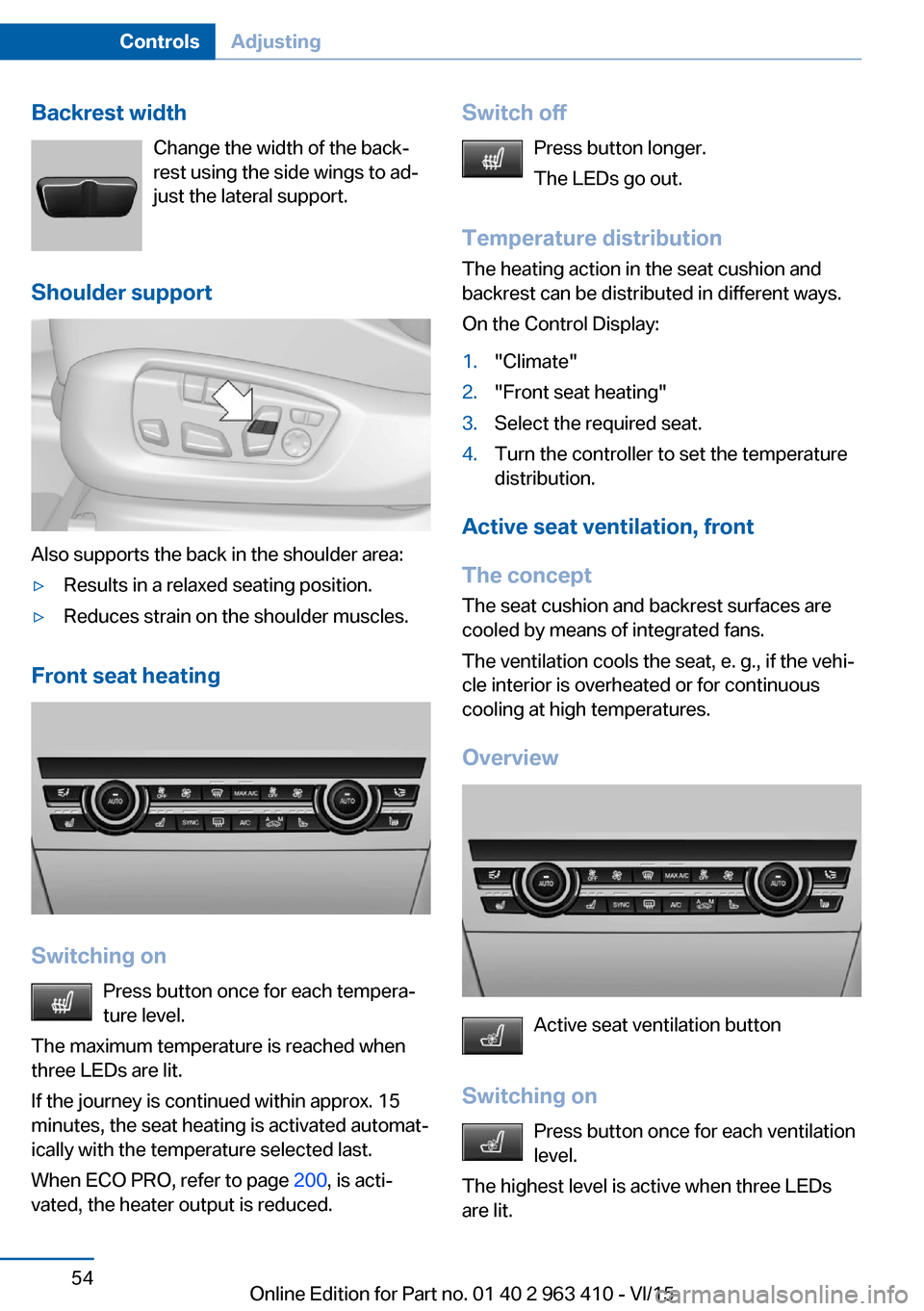
Backrest widthChange the width of the back‐
rest using the side wings to ad‐
just the lateral support.
Shoulder support
Also supports the back in the shoulder area:
▷Results in a relaxed seating position.▷Reduces strain on the shoulder muscles.
Front seat heating
Switching on Press button once for each tempera‐
ture level.
The maximum temperature is reached when
three LEDs are lit.
If the journey is continued within approx. 15
minutes, the seat heating is activated automat‐
ically with the temperature selected last.
When ECO PRO, refer to page 200, is acti‐
vated, the heater output is reduced.
Switch off
Press button longer.
The LEDs go out.
Temperature distribution
The heating action in the seat cushion and
backrest can be distributed in different ways.
On the Control Display:1."Climate"2."Front seat heating"3.Select the required seat.4.Turn the controller to set the temperature
distribution.
Active seat ventilation, front
The concept The seat cushion and backrest surfaces are
cooled by means of integrated fans.
The ventilation cools the seat, e. g., if the vehi‐
cle interior is overheated or for continuous
cooling at high temperatures.
Overview
Active seat ventilation button
Switching on Press button once for each ventilation
level.
The highest level is active when three LEDs
are lit.
Seite 54ControlsAdjusting54
Online Edition for Part no. 01 40 2 963 410 - VI/15
Page 90 of 275
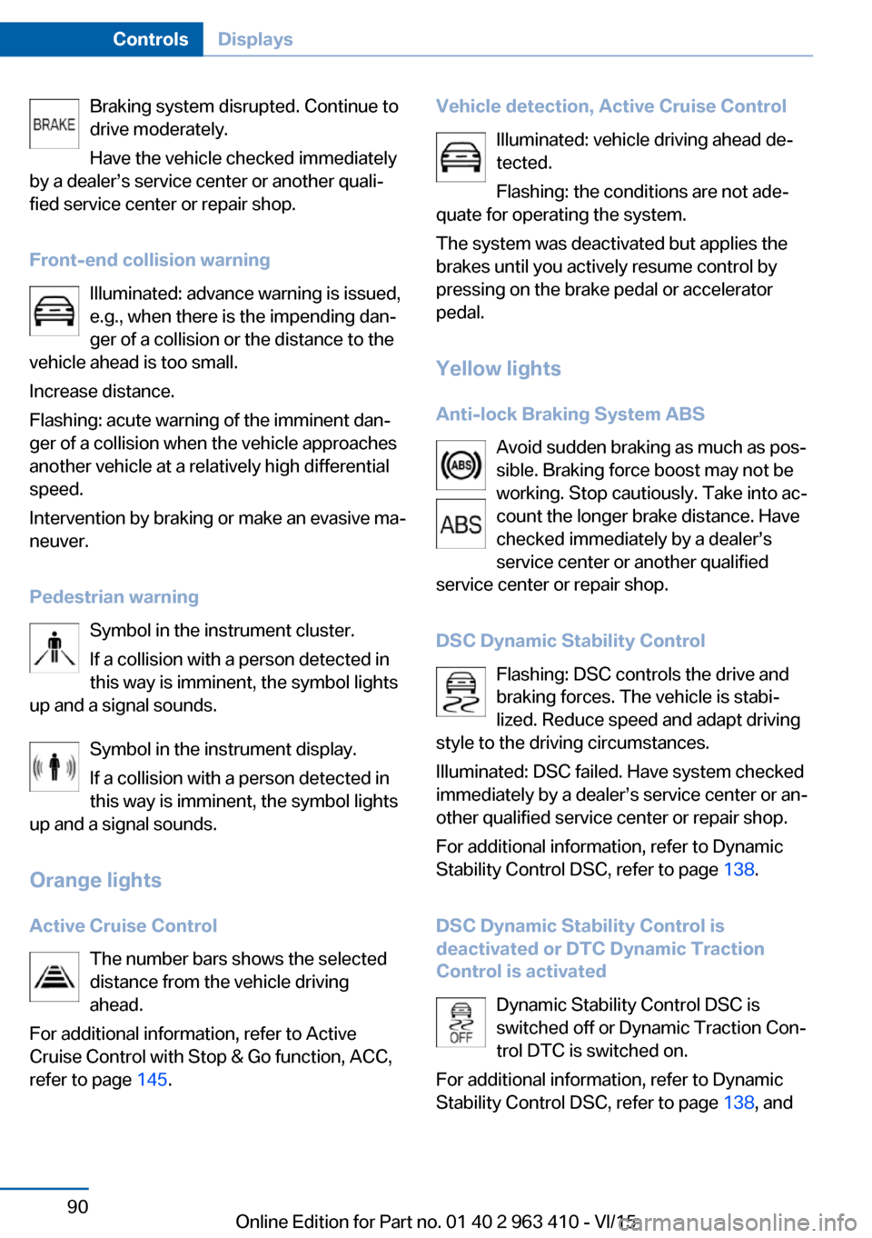
Braking system disrupted. Continue to
drive moderately.
Have the vehicle checked immediately
by a dealer’s service center or another quali‐
fied service center or repair shop.
Front-end collision warning Illuminated: advance warning is issued,
e.g., when there is the impending dan‐
ger of a collision or the distance to the
vehicle ahead is too small.
Increase distance.
Flashing: acute warning of the imminent dan‐
ger of a collision when the vehicle approaches
another vehicle at a relatively high differential
speed.
Intervention by braking or make an evasive ma‐
neuver.
Pedestrian warning Symbol in the instrument cluster.
If a collision with a person detected in
this way is imminent, the symbol lights
up and a signal sounds.
Symbol in the instrument display.
If a collision with a person detected in
this way is imminent, the symbol lights
up and a signal sounds.
Orange lights
Active Cruise Control The number bars shows the selected
distance from the vehicle driving
ahead.
For additional information, refer to Active
Cruise Control with Stop & Go function, ACC,
refer to page 145.Vehicle detection, Active Cruise Control
Illuminated: vehicle driving ahead de‐tected.
Flashing: the conditions are not ade‐
quate for operating the system.
The system was deactivated but applies the
brakes until you actively resume control by
pressing on the brake pedal or accelerator
pedal.
Yellow lights
Anti-lock Braking System ABS Avoid sudden braking as much as pos‐
sible. Braking force boost may not be
working. Stop cautiously. Take into ac‐
count the longer brake distance. Have
checked immediately by a dealer’s
service center or another qualified
service center or repair shop.
DSC Dynamic Stability Control Flashing: DSC controls the drive and
braking forces. The vehicle is stabi‐
lized. Reduce speed and adapt driving
style to the driving circumstances.
Illuminated: DSC failed. Have system checked
immediately by a dealer’s service center or an‐
other qualified service center or repair shop.
For additional information, refer to Dynamic
Stability Control DSC, refer to page 138.
DSC Dynamic Stability Control is
deactivated or DTC Dynamic Traction
Control is activated
Dynamic Stability Control DSC is
switched off or Dynamic Traction Con‐
trol DTC is switched on.
For additional information, refer to Dynamic
Stability Control DSC, refer to page 138, andSeite 90ControlsDisplays90
Online Edition for Part no. 01 40 2 963 410 - VI/15
Page 97 of 275
Speed limit detectionCurrent speed limit.
Speed limit detection is not
available.
Speed limit detection can also be displayed in
the Head-up Display.
System limits
The system may not be fully functional and
may provide incorrect information in the fol‐
lowing situations:▷In heavy fog, rain or snowfall.▷When signs are concealed by objects.▷When driving very close to the vehicle in
front of you.▷When driving toward bright lights.▷When the windshield behind the interior
rearview mirror is fogged over, dirty or cov‐
ered by a sticker, etc.▷In the event of incorrect detection by the
camera.▷If the speed limits stored in the navigation
system are incorrect.▷In areas not covered by the navigation sys‐
tem.▷When roads differ from the navigation,
such as due to changes in road routing.▷When passing buses or trucks with a
speed sticker.▷If the traffic signs are non-conforming.▷During calibration of the camera immedi‐
ately after vehicle delivery.Selection lists in the
instrument cluster
The concept Depending on your vehicle's optional features,
the following can be displayed or operated us‐
ing the buttons and the thumbwheel on the
steering wheel as well as the displays in the in‐
strument cluster and the Head-up Display:▷Current audio source.▷Redial phone feature.▷Turn on voice activation system.
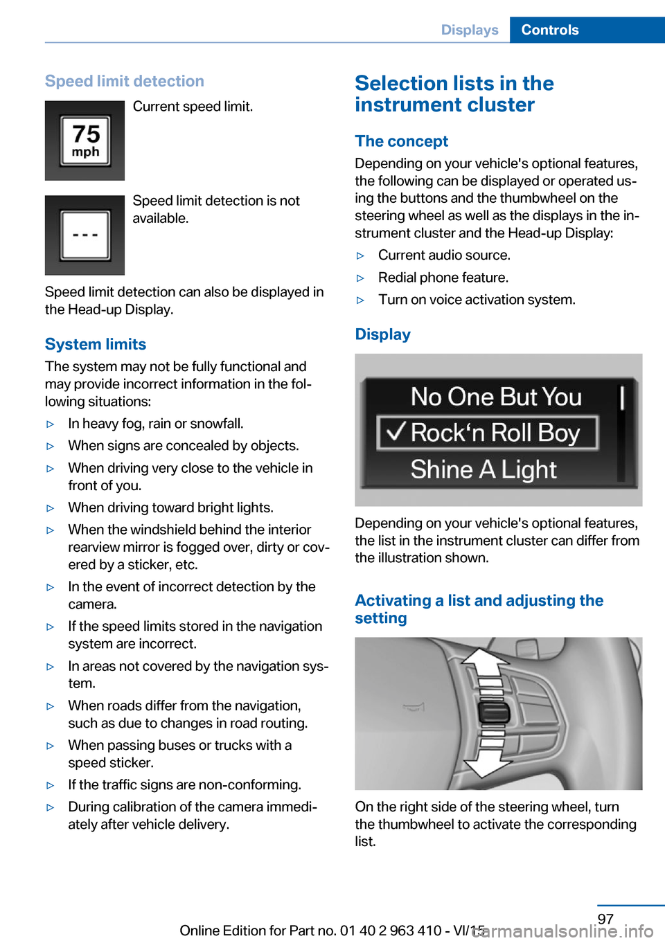
Display
Depending on your vehicle's optional features,
the list in the instrument cluster can differ from
the illustration shown.
Activating a list and adjusting the
setting
On the right side of the steering wheel, turn
the thumbwheel to activate the corresponding
list.
Seite 97DisplaysControls97
Online Edition for Part no. 01 40 2 963 410 - VI/15
Page 118 of 275
The possible driving distance after a loss of tire
inflation pressure depends on cargo load, driv‐
ing style and road conditions.
A vehicle with an average load has a possible
driving range of approx. 50 miles/80 km.
A vehicle with a damaged tire reacts differ‐
ently, e.g., it has reduced lane stability during
braking, a longer braking distance and different
self-steering properties. Adjust your driving
style accordingly. Avoid abrupt steering ma‐
neuvers or driving over obstacles, e.g., curbs,
potholes, etc.
Because the possible driving distance de‐
pends on how the vehicle is used during the
trip, the actual distance may be shorter or lon‐
ger depending on the driving speed, road con‐
ditions, external temperature, cargo load, etc.
WARNING
Your vehicle handles differently when a
run-flat tire is damaged and has low or missing
tire inflation pressure, e.g., your lane stability is
reduced when braking, braking distances are
longer and the self-steering properties will
change. There is risk of an accident.
Drive moderately and do not exceed a speed of
50 mph/80 km/h.◀
Final tire failure
Vibrations or loud noises while driving can indi‐
cate the final failure of a tire.
Reduce speed and stop; otherwise, pieces of
the tire could come loose and cause an acci‐
dent.
Do not continue driving. Contact a dealer’s
service center or another qualified service cen‐
ter or repair shop.
Intelligent Safety The concept
Intelligent Safety enables central operation of
the driver assistance system. Depending onhow the vehicle is equipped, Intelligent Safety
consists of one or more systems that can help
prevent a imminent collision.▷Front-end collision warning, refer to
page 119.▷Pedestrian warning, refer to page 125.▷Lane departure warning, refer to
page 131.▷Active Blind Spot Detection, refer to
page 133.
Information
WARNING
Indicators and warnings do not relieve
from the personal responsibility. Due to sys‐
tem limits, warnings or reactions of the system
may not be output or they may be output too
late or incorrectly. There is risk of an accident.
Adjust the driving style to the traffic condi‐
tions. Watch traffic closely and actively inter‐
fere in the respective situations.◀
WARNING
Due to system limits, individual functions
can malfunction during tow-starting/towing
with the Intelligent Safety systems activated,
e.g. approach control warning with light brak‐
ing function. There is risk of an accident.
Switch all Intelligent Safety systems off prior to
tow-starting/towing.◀
Overview
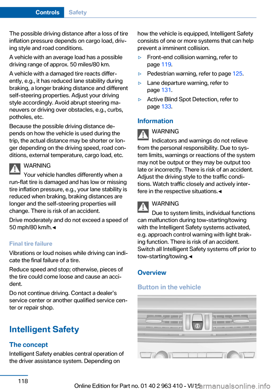
Button in the vehicle
Seite 118ControlsSafety118
Online Edition for Part no. 01 40 2 963 410 - VI/15
Page 141 of 275
Display in the instrument clusterThe selected speed is displayed
in the speedometer.▷Green: the system is actively
braking the vehicle.▷Orange: the system is on
standby.
Malfunction
A message is displayed in the instrument clus‐
ter. HDC is not available, e.g., due to elevated
brake temperatures.
Active Steering
Active Steering varies the steering angle of the
wheels in relation to the steering wheel move‐
ment as a function of the speed.
At lower speeds, for example during turning or
maneuvering, the steering angle is increased,
that is to say the steering becomes more di‐
rect.
At higher speeds, the steering angle is increas‐
ingly reduced.
This enables even more precise handling at
high speeds and more responsive steering
with reduced steering angle at low speeds.
Active roll stabilization The concept
The system reduces the lateral inclination of
the vehicle that occurs during rapid driving in
curves or during quick evasive maneuvers.
Driving stability and driving comfort are in‐
creased under all driving conditions. The sys‐
tem utilizes active stabilizer bars on the front
and rear axles that react immediately to all driv‐
ing situations.
Programs
The system offers two different programs.
Select the programs via the Driving Dynamics
Control, refer to page 142.
SPORT Sporty tuning for greater driving agility.
COMFORT
Comfort-oriented tuning for optimal comfort.
Vertical Dynamic Control The concept This system reduces undesirable vehicle mo‐
tion when using a dynamic driving style or trav‐
eling on uneven road surfaces.
The system enhances driving dynamics and
comfort fitting road surface and driving style.
Programs The system offers several different programs.
Select the programs via the Driving Dynamics
Control, refer to page 142.
SPORT/SPORT+
Consistently sporty control of the shock ab‐
sorbers for greater driving agility.
COMFORT/ECO PRO Balanced tuning.
Self-leveling suspension The concept
The self-leveling suspension keeps the vehicle
height and ground clearance constant. The
height of the vehicle at the rear axle is main‐
tained at a predefined level under all load con‐
ditions.Seite 141Driving stability control systemsControls141
Online Edition for Part no. 01 40 2 963 410 - VI/15
Page 150 of 275
The minimum speed that can be set is
20 mph/30 km/h. The maximum speed that
can be set depends on the vehicle.
The system can also be activated when sta‐
tionary.
Comply with the legal speed limit in every sit‐
uation when using the system.
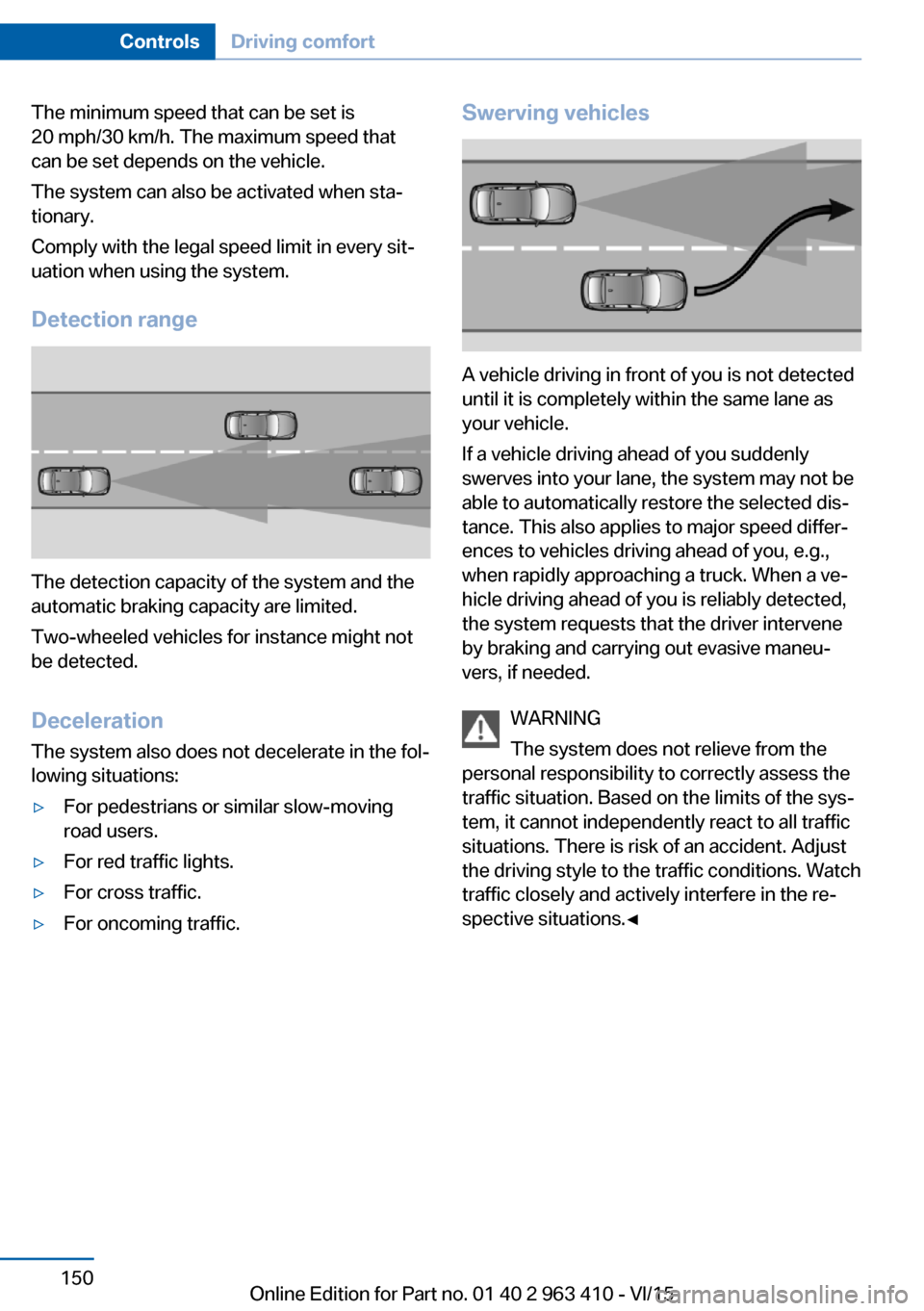
Detection range
The detection capacity of the system and the
automatic braking capacity are limited.
Two-wheeled vehicles for instance might not
be detected.
Deceleration
The system also does not decelerate in the fol‐
lowing situations:
▷For pedestrians or similar slow-moving
road users.▷For red traffic lights.▷For cross traffic.▷For oncoming traffic.Swerving vehicles
A vehicle driving in front of you is not detected
until it is completely within the same lane as
your vehicle.
If a vehicle driving ahead of you suddenly
swerves into your lane, the system may not be
able to automatically restore the selected dis‐
tance. This also applies to major speed differ‐
ences to vehicles driving ahead of you, e.g.,
when rapidly approaching a truck. When a ve‐
hicle driving ahead of you is reliably detected,
the system requests that the driver intervene
by braking and carrying out evasive maneu‐
vers, if needed.
WARNING
The system does not relieve from the
personal responsibility to correctly assess the
traffic situation. Based on the limits of the sys‐
tem, it cannot independently react to all traffic
situations. There is risk of an accident. Adjust
the driving style to the traffic conditions. Watch
traffic closely and actively interfere in the re‐
spective situations.◀
Seite 150ControlsDriving comfort150
Online Edition for Part no. 01 40 2 963 410 - VI/15
Page 162 of 275
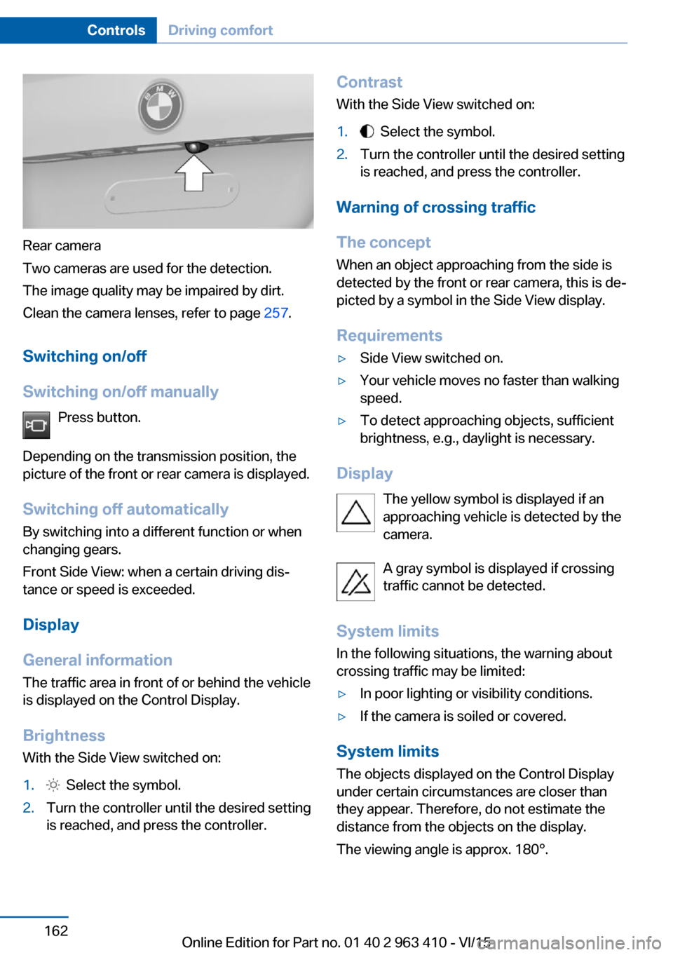
Rear camera
Two cameras are used for the detection.
The image quality may be impaired by dirt.
Clean the camera lenses, refer to page 257.
Switching on/off
Switching on/off manually Press button.
Depending on the transmission position, the
picture of the front or rear camera is displayed.
Switching off automatically By switching into a different function or when
changing gears.
Front Side View: when a certain driving dis‐
tance or speed is exceeded.
Display
General information
The traffic area in front of or behind the vehicle
is displayed on the Control Display.
Brightness With the Side View switched on:
1. Select the symbol.2.Turn the controller until the desired setting
is reached, and press the controller.Contrast
With the Side View switched on:1. Select the symbol.2.Turn the controller until the desired setting
is reached, and press the controller.
Warning of crossing traffic
The concept When an object approaching from the side is
detected by the front or rear camera, this is de‐
picted by a symbol in the Side View display.
Requirements
▷Side View switched on.▷Your vehicle moves no faster than walking
speed.▷To detect approaching objects, sufficient
brightness, e.g., daylight is necessary.
Display
The yellow symbol is displayed if anapproaching vehicle is detected by the
camera.
A gray symbol is displayed if crossing
traffic cannot be detected.
System limits
In the following situations, the warning about
crossing traffic may be limited:
▷In poor lighting or visibility conditions.▷If the camera is soiled or covered.
System limits
The objects displayed on the Control Display
under certain circumstances are closer than
they appear. Therefore, do not estimate the
distance from the objects on the display.
The viewing angle is approx. 180°.
Seite 162ControlsDriving comfort162
Online Edition for Part no. 01 40 2 963 410 - VI/15
Page 168 of 275
Climate control functions in detail
Switching the system on/off
Switching on
Press any button except:▷Rear window defroster.▷Left side of Air volume button.▷Seat heating.▷Seat ventilation.▷If necessary, SYNC program.
Switch off
▷Complete system: Press and hold the left button on
the driver's side until the control
clicks off.▷On the front passenger side:
Press and hold the left button on
the front passenger side.
Temperature
Turn the ring to set the desired
temperature.
The automatic climate control achieves this
temperature as quickly as possible, if needed
by using the maximum cooling or heating ca‐
pacity, and then keeps it constant.
Do not rapidly switch between different tem‐
perature settings. Otherwise, the automatic cli‐
mate control will not have sufficient time to ad‐
just the set temperature.
Cooling function
The car's interior can only be cooled with the
engine running.
Press button.
The air will be cooled and dehumidified and,
depending on the temperature setting,
warmed again.
Depending on the weather, the windshield and
side windows may fog up briefly when the en‐
gine is started.
The cooling function is switched on automati‐
cally with the AUTO program.
When using the automatic climate control,
condensation water, refer to page 195, devel‐
ops that exits underneath the vehicle.
Maximum cooling Press button.
The system is set to the lowest tem‐
perature, optimum air flow and air circulation mode.
Air flows out of the vents to the upper body re‐
gion. The vents need to be open for this.
The function is available above an external
temperature of approx. 32 ℉/0 ℃ and with the
engine running is indicated.
Adjust air flow with the program active.
AUTO program Press button.
Air flow, air distribution and tempera‐
ture are controlled automatically.
Depending on the selected temperature,
AUTO intensity program and outside influen‐
ces, the air is directed to the windshield, side
windows, upper body, and into the footwell.
The cooling function, refer to page 168, is
switched on automatically with the AUTO pro‐
gram.
At the same time, a condensation sensor con‐
trols the program so as to prevent window
condensation as much as possible.Seite 168ControlsClimate control168
Online Edition for Part no. 01 40 2 963 410 - VI/15
Page 176 of 275
4.Likewise, press and hold the button of the
desired function on the hand-held trans‐
mitter.5.Release both buttons as soon as the inte‐
rior rearview mirror LED flashes more rap‐
idly. The LED flashing faster indicates that
the button on the interior rearview mirror
has been programmed. The system can
then be controlled by the button on the in‐
terior rearview mirror.
If the LED does not flash faster after at
least 60 seconds, change the distance and
repeat the step. Several more attempts at
different distances may be necessary. Wait
at least 15 seconds between attempts.
Canada: if programming with the hand-
held transmitter was interrupted, hold
down the interior rearview mirror button
and repeatedly press and release the
hand-held transmitter button for 2 sec‐
onds.
Controls
WARNING
Body parts can be jammed when operat‐
ing remote-controlled systems, e.g. the garage
door, using the universal garage door opener. There is risk of injuries or risk of property dam‐
age. Make sure that the area of movement of
the respective system is clear during program‐
ming and operation. Also follow the safety in‐
structions of the hand-held transmitter.◀
The system, such as the garage door, can be
operated using the button on the interior rear‐
view mirror while the engine is running or when
the ignition is started. To do this, hold down
the button within receiving range of the system
until the function is activated. The interior rear‐
view mirror LED stays lit while the wireless sig‐
nal is being transmitted.
Deleting stored functions Press and hold the left and right button on the
interior rearview mirror simultaneously for ap‐
proximately 20 seconds until the LED flashes
rapidly. All stored functions are deleted. The
functions cannot be deleted individually.
Sun visor Glare shieldFold the sun visor down or up.
Glare shield from the side
Folding out1.Fold the sun visor down.2.Unhook it from the holder and swing it to
the side.3.Move it back to the desired position.
Folding up
Proceed in the reverse order to close the sun
visor.
Vanity mirror A vanity mirror is located in the sun visor be‐
hind a cover. When the cover is opened, the
mirror lighting switches on.
Ashtray
Front
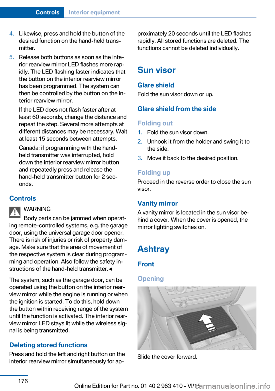
Opening
Slide the cover forward.
Seite 176ControlsInterior equipment176
Online Edition for Part no. 01 40 2 963 410 - VI/15
Page 224 of 275
tolerances despite the same official size rating.
There is risk of an accident.◀
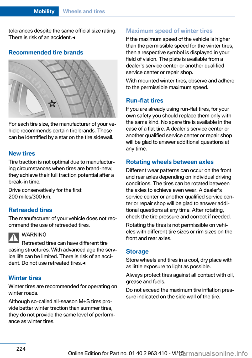
Recommended tire brands
For each tire size, the manufacturer of your ve‐
hicle recommends certain tire brands. These
can be identified by a star on the tire sidewall.
New tires
Tire traction is not optimal due to manufactur‐
ing circumstances when tires are brand-new;
they achieve their full traction potential after a
break-in time.
Drive conservatively for the first
200 miles/300 km.
Retreaded tires
The manufacturer of your vehicle does not rec‐
ommend the use of retreaded tires.
WARNING
Retreated tires can have different tire
casing structures. With advanced age the serv‐
ice life can be limited. There is risk of an acci‐
dent. Do not use retreated tires.◀
Winter tires
Winter tires are recommended for operating on winter roads.
Although so-called all-season M+S tires pro‐
vide better winter traction than summer tires,
they do not provide the same level of perform‐
ance as winter tires.
Maximum speed of winter tires
If the maximum speed of the vehicle is higher
than the permissible speed for the winter tires,
then a respective symbol is displayed in your
field of vision. The plate is available from a
dealer’s service center or another qualified
service center or repair shop.
With mounted winter tires, observe and adhere
to the permissible maximum speed.
Run-flat tires If you are already using run-flat tires, for your
own safety you should replace them only with
the same kind. No spare tire is available in the
case of a flat tire. A dealer’s service center or
another qualified service center or repair shop
will be glad to answer additional questions at
any time.
Rotating wheels between axles Different wear patterns can occur on the front
and rear axles depending on individual driving
conditions. The tires can be rotated between
the axles to achieve even wear. A dealer’s
service center or another qualified service cen‐
ter or repair shop will be glad to answer addi‐
tional questions at any time. After rotating,
check the tire pressure and correct if needed.
Rotating the tires is not permissible on vehi‐
cles with different tire sizes or rim sizes on the
front and rear axles.
Storage
Store wheels and tires in a cool, dry place with
as little exposure to light as possible.
Always protect tires against all contact with oil,
grease and fuels.
Do not exceed the maximum tire inflation pres‐
sure indicated on the side wall of the tire.Seite 224MobilityWheels and tires224
Online Edition for Part no. 01 40 2 963 410 - VI/15