sensor BMW X5 2016 F15 User Guide
[x] Cancel search | Manufacturer: BMW, Model Year: 2016, Model line: X5, Model: BMW X5 2016 F15Pages: 275, PDF Size: 6.46 MB
Page 123 of 275
Overview
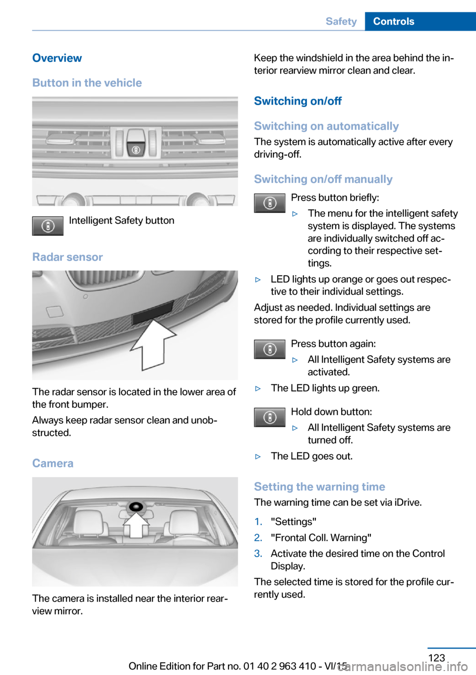
Button in the vehicle
Intelligent Safety button
Radar sensor
The radar sensor is located in the lower area of
the front bumper.
Always keep radar sensor clean and unob‐
structed.
Camera
The camera is installed near the interior rear‐
view mirror.
Keep the windshield in the area behind the in‐
terior rearview mirror clean and clear.
Switching on/off
Switching on automatically The system is automatically active after every
driving-off.
Switching on/off manually Press button briefly:▷The menu for the intelligent safety
system is displayed. The systems
are individually switched off ac‐
cording to their respective set‐
tings.▷LED lights up orange or goes out respec‐
tive to their individual settings.
Adjust as needed. Individual settings are
stored for the profile currently used.
Press button again:
▷All Intelligent Safety systems are
activated.▷The LED lights up green.
Hold down button:
▷All Intelligent Safety systems are
turned off.▷The LED goes out.
Setting the warning time
The warning time can be set via iDrive.
1."Settings"2."Frontal Coll. Warning"3.Activate the desired time on the Control
Display.
The selected time is stored for the profile cur‐
rently used.
Seite 123SafetyControls123
Online Edition for Part no. 01 40 2 963 410 - VI/15
Page 125 of 275
the mirror or the radar sensor is dirty or ob‐
scured.▷Up to 10 seconds after the start of the en‐
gine, via the Start/Stop button.▷During calibration of the camera immedi‐
ately after vehicle delivery.▷If there are constant blinding effects be‐
cause of oncoming light, e. g., from the sun
low in the sky.
Warning sensitivity
The more sensitive the warning settings are,
e.g. the warning time, the more warnings are
displayed. However, there may also be an ex‐
cess of false warnings.
Pedestrian warning
Depending on how the vehicle is equipped, the
function warns of an imminent collision with
pedestrians during daytime or nighttime.
The function is subdivided into the following
systems:
▷During daytime: Pedestrian warning with
city braking function, refer to page 125▷At night: Night vision, refer to page 127
Pedestrian warning with city
braking function
The concept The system can help prevent accidents with
pedestrians.
The system issues a warning in the city driving
speed area if there is imminent danger of a col‐
lision with pedestrians and includes a braking
function.
The camera in the area of the rearview mirror
controls the system.
General information
With sufficient brightness, the system warns
about possible collision danger with pedes‐
trians starting at approx. 6 mph/10 km/h to ap‐
prox. 35 mph/60 km/h and assists with braking
before a collision.
Under those circumstances it reacts to people
who are within the detection range of the sys‐
tem.
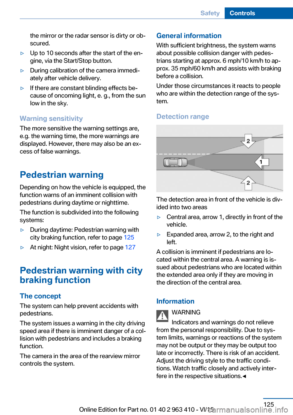
Detection range
The detection area in front of the vehicle is div‐
ided into two areas
▷Central area, arrow 1, directly in front of the
vehicle.▷Expanded area, arrow 2, to the right and
left.
A collision is imminent if pedestrians are lo‐
cated within the central area. A warning is is‐
sued about pedestrians who are located within
the extended area only if they are moving in
the direction of the central area.
Information WARNING
Indicators and warnings do not relieve
from the personal responsibility. Due to sys‐
tem limits, warnings or reactions of the system
may not be output or they may be output too
late or incorrectly. There is risk of an accident.
Adjust the driving style to the traffic condi‐
tions. Watch traffic closely and actively inter‐
fere in the respective situations.◀
Seite 125SafetyControls125
Online Edition for Part no. 01 40 2 963 410 - VI/15
Page 133 of 275
Active Blind Spot Detection
The concept
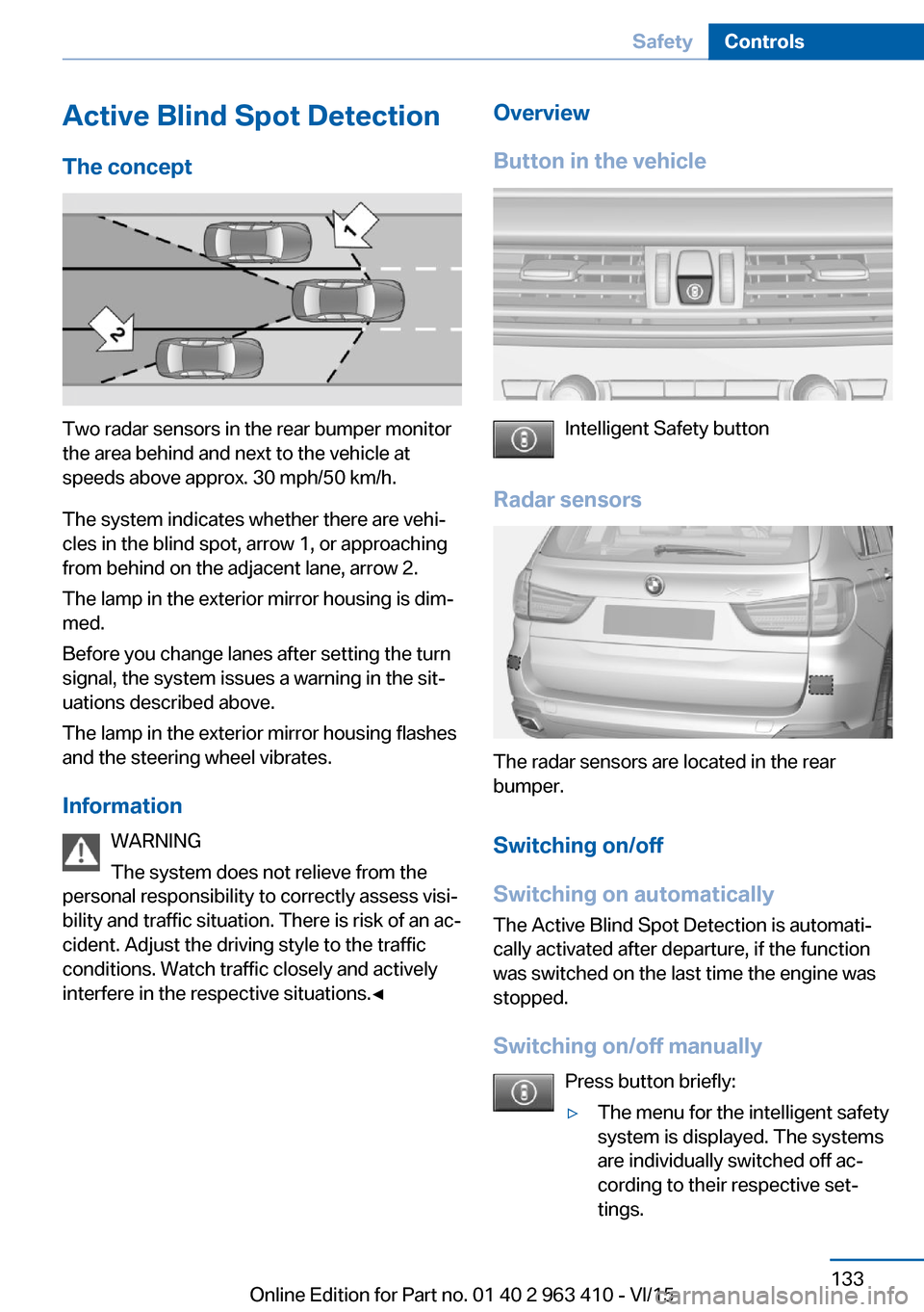
Two radar sensors in the rear bumper monitor
the area behind and next to the vehicle at
speeds above approx. 30 mph/50 km/h.
The system indicates whether there are vehi‐
cles in the blind spot, arrow 1, or approaching
from behind on the adjacent lane, arrow 2.
The lamp in the exterior mirror housing is dim‐
med.
Before you change lanes after setting the turn
signal, the system issues a warning in the sit‐
uations described above.
The lamp in the exterior mirror housing flashes
and the steering wheel vibrates.
Information WARNING
The system does not relieve from the
personal responsibility to correctly assess visi‐
bility and traffic situation. There is risk of an ac‐
cident. Adjust the driving style to the traffic
conditions. Watch traffic closely and actively interfere in the respective situations.◀
Overview
Button in the vehicle
Intelligent Safety button
Radar sensors
The radar sensors are located in the rear
bumper.
Switching on/off
Switching on automatically The Active Blind Spot Detection is automati‐
cally activated after departure, if the function
was switched on the last time the engine was
stopped.
Switching on/off manually Press button briefly:
▷The menu for the intelligent safety
system is displayed. The systems
are individually switched off ac‐
cording to their respective set‐
tings.Seite 133SafetyControls133
Online Edition for Part no. 01 40 2 963 410 - VI/15
Page 146 of 275
Overview
Buttons on the steering wheelPress but‐
tonFunctionCruise control on/off, interrupt,
refer to page 146Store/maintain speed, refer to
page 147Resume speed, refer to
page 148Reduce distance, refer to
page 148Increase distance, refer to
page 148Rocker switch:
Maintain, store, change speed,
refer to page 147
Buttons are arranged according to vehicle's
series, optional features and country specifica‐
tions.
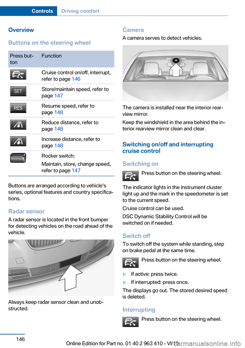
Radar sensor
A radar sensor is located in the front bumper for detecting vehicles on the road ahead of the
vehicle.
Always keep radar sensor clean and unob‐
structed.
Camera
A camera serves to detect vehicles.
The camera is installed near the interior rear‐
view mirror.
Keep the windshield in the area behind the in‐
terior rearview mirror clean and clear.
Switching on/off and interrupting
cruise control
Switching on Press button on the steering wheel.
The indicator lights in the instrument cluster
light up and the mark in the speedometer is set
to the current speed.
Cruise control can be used.
DSC Dynamic Stability Control will be
switched on if needed.
Switch off To switch off the system while standing, step
on brake pedal at the same time.
Press button on the steering wheel.
▷If active: press twice.▷If interrupted: press once.
The displays go out. The stored desired speed
is deleted.
Interrupting Press button on the steering wheel.
Seite 146ControlsDriving comfort146
Online Edition for Part no. 01 40 2 963 410 - VI/15
Page 148 of 275
▷Each time the rocker switch is pressed
past the point of resistance, the desired
speed increases or decreases by a maxi‐
mum of 5 mph/10 km/h.
Hold the rocker switch in position to repeat the
action.
Distance WARNING
The system does not relieve from the
personal responsibility. Due to the system lim‐
its, braking can be late. There is risk of acci‐
dents or risk of property damage. Be aware to
the traffic situation at all times. Adjust the dis‐
tance to the traffic and weather conditions and
maintain the prescribed safety distance, possi‐
bly by braking.◀
Reduce distance Press button repeatedly until the de‐
sired distance is set.
Instrument cluster will display selected dis‐
tance, refer to page 149.
Increase distance Press button repeatedly until the de‐
sired distance is set.
Instrument cluster will display selected dis‐
tance, refer to page 149.
Calling up the desired speed and distance
While driving Press button with the system
switched on.
In the following cases, the stored speed value
is deleted and cannot be called up again:
▷When the system is switched off.▷When the ignition is switched off.While standing
The system brought the vehicle to a complete
standstill:▷Green marking in the speedometer:
Your vehicle accelerates automatically as
soon as the vehicle in the range of the ra‐
dar sensor moves off.▷Speedometer markings turn orange: no au‐
tomatic driving off.
To accelerate to the desired speed auto‐
matically, press the accelerator or press
the RES or SET button.
Rolling bars in the distance display indicate
that the vehicle detected by the radar sensor
has driven off.
The system was paused or your vehicle was
brought to a halt actively through stepping on
the brake pedal and it is standing behind an‐
other vehicle:
1. Press button to call up a stored
desired speed.2.Release the brake pedal.3.Step on the accelerator briefly, or press the
RES rocker switch when the vehicle ahead
of you drives away.
Displays in the instrument cluster
Desired speed
▷The marking lights up green:
the system is active.▷The marking lights up or‐
ange: the system has been
interrupted.▷The marking does not light up: the system
is switched off.
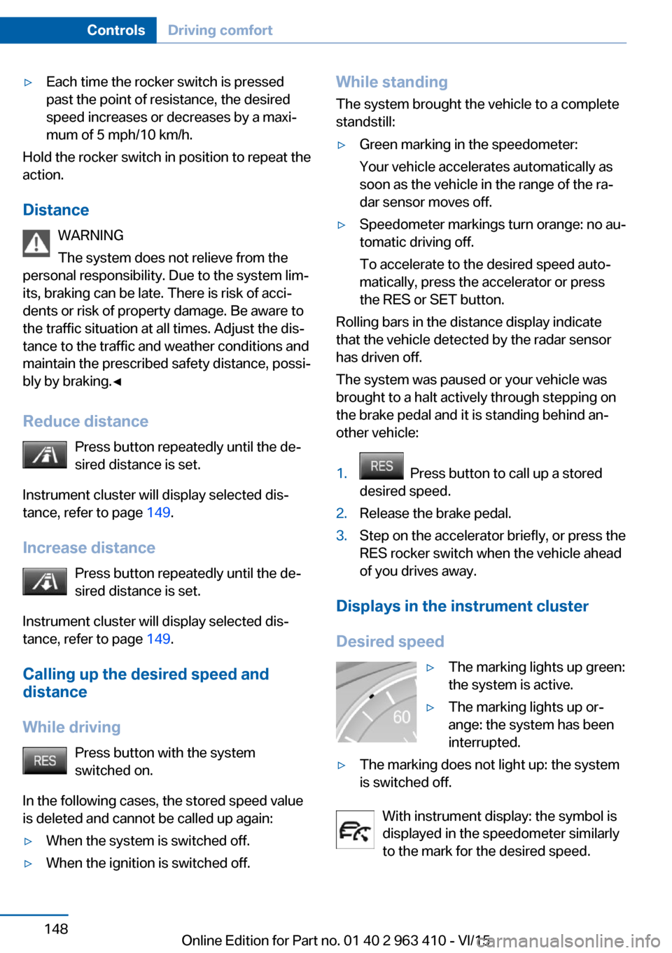
With instrument display: the symbol is
displayed in the speedometer similarly
to the mark for the desired speed.
Seite 148ControlsDriving comfort148
Online Edition for Part no. 01 40 2 963 410 - VI/15
Page 151 of 275
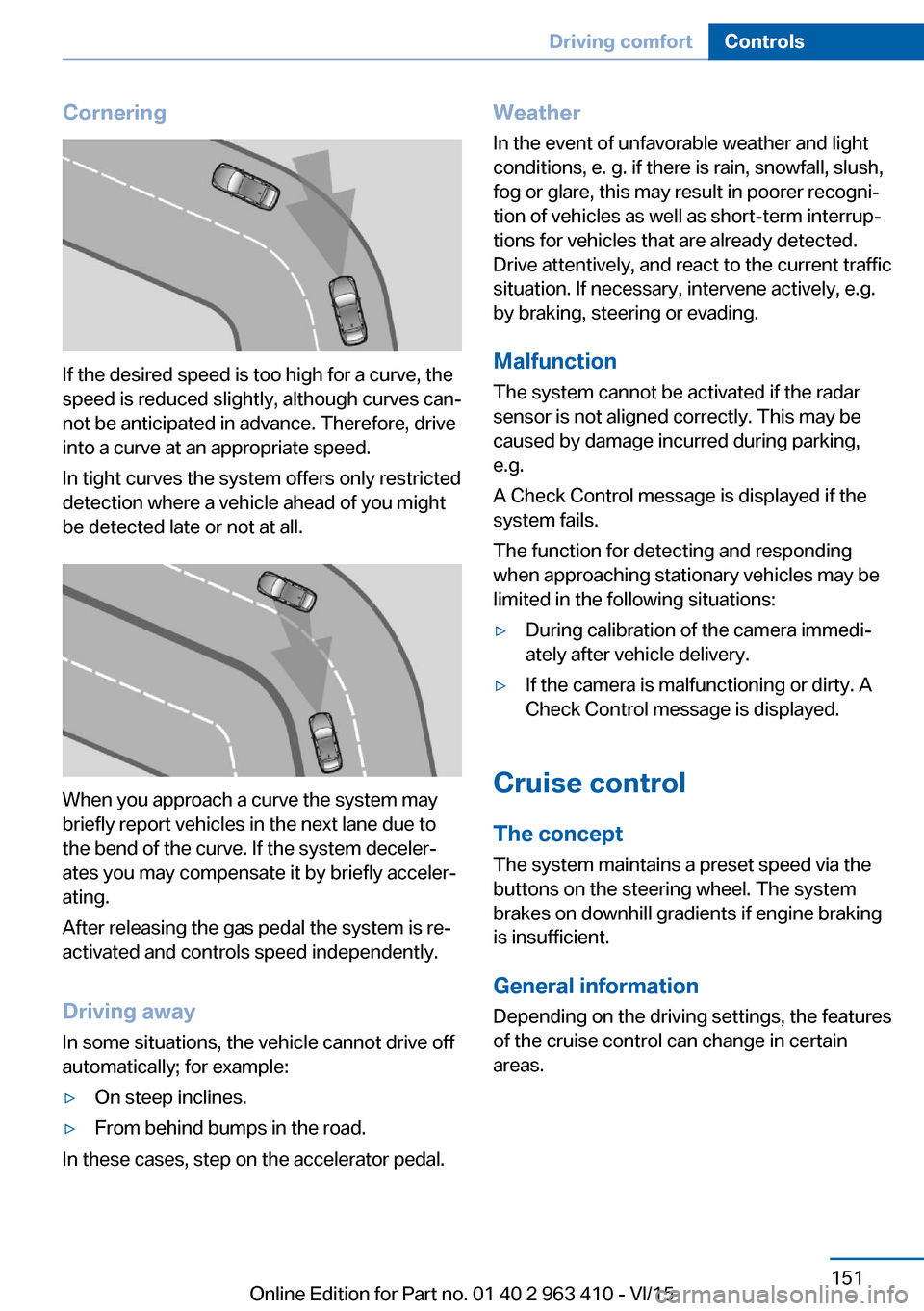
Cornering
If the desired speed is too high for a curve, the
speed is reduced slightly, although curves can‐
not be anticipated in advance. Therefore, drive
into a curve at an appropriate speed.
In tight curves the system offers only restricted
detection where a vehicle ahead of you might
be detected late or not at all.
When you approach a curve the system may
briefly report vehicles in the next lane due to
the bend of the curve. If the system deceler‐
ates you may compensate it by briefly acceler‐
ating.
After releasing the gas pedal the system is re‐
activated and controls speed independently.
Driving away In some situations, the vehicle cannot drive off
automatically; for example:
▷On steep inclines.▷From behind bumps in the road.
In these cases, step on the accelerator pedal.
Weather
In the event of unfavorable weather and light conditions, e. g. if there is rain, snowfall, slush,
fog or glare, this may result in poorer recogni‐
tion of vehicles as well as short-term interrup‐
tions for vehicles that are already detected. Drive attentively, and react to the current trafficsituation. If necessary, intervene actively, e.g.
by braking, steering or evading.
Malfunction
The system cannot be activated if the radar sensor is not aligned correctly. This may be
caused by damage incurred during parking,
e.g.
A Check Control message is displayed if the
system fails.
The function for detecting and responding
when approaching stationary vehicles may be limited in the following situations:▷During calibration of the camera immedi‐
ately after vehicle delivery.▷If the camera is malfunctioning or dirty. A
Check Control message is displayed.
Cruise control
The concept The system maintains a preset speed via the
buttons on the steering wheel. The system
brakes on downhill gradients if engine braking
is insufficient.
General information
Depending on the driving settings, the features
of the cruise control can change in certain
areas.
Seite 151Driving comfortControls151
Online Edition for Part no. 01 40 2 963 410 - VI/15
Page 154 of 275
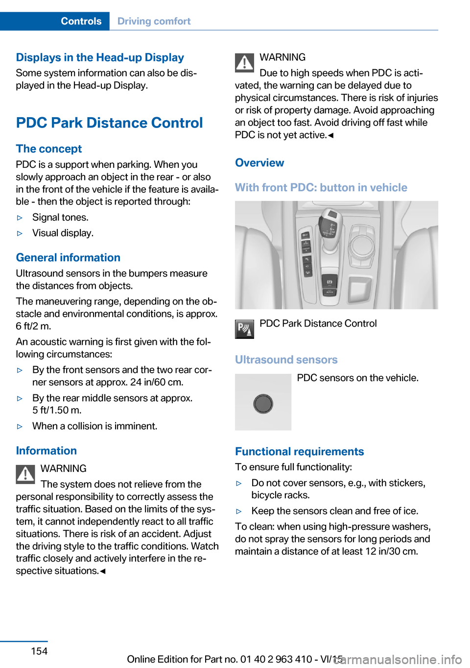
Displays in the Head-up DisplaySome system information can also be dis‐
played in the Head-up Display.
PDC Park Distance Control
The concept PDC is a support when parking. When you
slowly approach an object in the rear - or also
in the front of the vehicle if the feature is availa‐
ble - then the object is reported through:▷Signal tones.▷Visual display.
General information
Ultrasound sensors in the bumpers measure
the distances from objects.
The maneuvering range, depending on the ob‐
stacle and environmental conditions, is approx.
6 ft/2 m.
An acoustic warning is first given with the fol‐
lowing circumstances:
▷By the front sensors and the two rear cor‐
ner sensors at approx. 24 in/60 cm.▷By the rear middle sensors at approx.
5 ft/1.50 m.▷When a collision is imminent.
Information
WARNING
The system does not relieve from the
personal responsibility to correctly assess the
traffic situation. Based on the limits of the sys‐
tem, it cannot independently react to all traffic
situations. There is risk of an accident. Adjust
the driving style to the traffic conditions. Watch
traffic closely and actively interfere in the re‐
spective situations.◀
WARNING
Due to high speeds when PDC is acti‐
vated, the warning can be delayed due to
physical circumstances. There is risk of injuries
or risk of property damage. Avoid approaching
an object too fast. Avoid driving off fast while
PDC is not yet active.◀
Overview
With front PDC: button in vehicle
PDC Park Distance Control
Ultrasound sensors PDC sensors on the vehicle.
Functional requirements
To ensure full functionality:
▷Do not cover sensors, e.g., with stickers,
bicycle racks.▷Keep the sensors clean and free of ice.
To clean: when using high-pressure washers,
do not spray the sensors for long periods and
maintain a distance of at least 12 in/30 cm.
Seite 154ControlsDriving comfort154
Online Edition for Part no. 01 40 2 963 410 - VI/15
Page 155 of 275
Switching on/off
Switching on automatically PDC switches on automatically in the following
situations:▷If selector lever position R is engaged
when the engine is running.
The rearview camera also switches on.▷If equipped with front PDC: when obsta‐
cles are detected behind or in front of the
vehicle by PDC and the speed is slower
than approx. 2.5 mph/4 km/h.
You may turn off automatic activation:
1."Settings"2."Parking"3.Select setting.
Settings are stored for the profile currently
used.
Automatic deactivation during forward
travel
The system switches off when a certain driving
distance or speed is exceeded.
Switch the system back on if needed.
With front PDC: switching on/off
manually
Press button.
▷On: the LED lights up.▷Off: the LED goes out.
The rearview camera image is displayed when
the reverse gear is engaged by pressing the
button.
Display
Signal tones When approaching an object, an intermittent
sound indicates the position of the object. E. g.
if an object is detected to the left rear of the
vehicle, a signal tone sounds from the left rear
speaker.
The shorter the distance to the object, the
shorter the intervals.
If the distance to a detected object is less than
approx. 10 in/25 cm, a continuous tone is
sounded.
With front PDC: if objects are located both in
front of and behind the vehicle, an alternating
continuous signal is sounded.
The signal tone is switched off, when selector
lever position P is engaged on vehicles with
Steptronic transmission.
Volume
The ratio of the PDC signal tone volume to the
entertainment volume can be adjusted.1."Multimedia", "Radio" or "Settings"2."Tone"3."Volume settings"4."PDC"5.Turn the controller until the desired setting
is selected.6.Press the controller.
Settings are stored for the profile currently
used.
Visual warning
The approach of the vehicle to an object can
be shown on the Control Display. Objects that
are farther away are already displayed on the
Control Display before a signal sounds.
A display appears as soon as Park Distance
Control (PDC) is activated.
The range of the sensors is represented in the
colors green, yellow and red.
When the image of the rearview camera is dis‐
played, the switch can be made to PDC:
"Rear view camera"
Seite 155Driving comfortControls155
Online Edition for Part no. 01 40 2 963 410 - VI/15
Page 156 of 275
System limits
Limits of ultrasonic measurement
Ultrasonic measuring might not function under
the following circumstances:▷For small children and animals.▷For persons with certain clothing, e.g.
coats.▷With external interference of the ultra‐
sound, e.g. from passing vehicles or loud
machines.▷When sensors are dirty, iced over, dam‐
aged or out of position.▷Under certain weather conditions such as
high relative humidity, rain, snowfall, ex‐
treme heat or strong wind.▷With tow bars and trailer couplings of other
vehicles.▷With thin or wedge-shaped objects.▷With moving objects.▷With elevated, protruding objects such as
ledges or cargo.▷With objects with corners and sharp edges.▷With objects with a fine surface structure
such as fences.▷For objects with porous surfaces.
Low objects already displayed, e.g., curbs, can
move into the blind area of the sensors before
or after a continuous tone sounds.
False warnings
PDC may issue a warning under the following conditions even though there is no obstacle
within the detection range:
▷In heavy rain.▷When sensors are very dirty or covered
with ice.▷When sensors are covered in snow.▷On rough road surfaces.▷On uneven surfaces, such as speed
bumps.▷In large buildings with right angles and
smooth walls, e.g., in underground ga‐
rages.▷In automatic car washes.▷Through heavy pollution.▷Due to other ultrasound sources, e.g.,
sweeping machines, high pressure steam
cleaners or neon lights.
Malfunction
A Check Control message is displayed.
The range of the sensors is shown as a shaded
area on the Control Display.
PDC has failed. Have the system checked.
Surround View
The concept Surround View comprises various camera as‐
sistance systems that help the driver when
parking, maneuvering, and at complex exits
and intersections.
▷Rearview camera, refer to page 156.▷Top View, refer to page 159.▷Side View, refer to page 161.
Rearview camera
The concept The rearview camera provides assistance in
parking and maneuvering backwards. The area
behind the vehicle is shown on the Control
Display.
Information WARNING
The system does not relieve from the
personal responsibility to correctly assess the
traffic situation. There is risk of an accident.
Adjust the driving style to the traffic condi‐
Seite 156ControlsDriving comfort156
Online Edition for Part no. 01 40 2 963 410 - VI/15
Page 158 of 275
Pathway lines
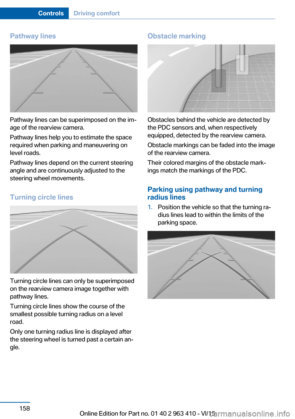
Pathway lines can be superimposed on the im‐
age of the rearview camera.
Pathway lines help you to estimate the space
required when parking and maneuvering on
level roads.
Pathway lines depend on the current steering
angle and are continuously adjusted to the
steering wheel movements.
Turning circle lines
Turning circle lines can only be superimposed
on the rearview camera image together with
pathway lines.
Turning circle lines show the course of the
smallest possible turning radius on a level
road.
Only one turning radius line is displayed after
the steering wheel is turned past a certain an‐
gle.
Obstacle marking
Obstacles behind the vehicle are detected by
the PDC sensors and, when respectively
equipped, detected by the rearview camera.
Obstacle markings can be faded into the image
of the rearview camera.
Their colored margins of the obstacle mark‐
ings match the markings of the PDC.
Parking using pathway and turning
radius lines
1.Position the vehicle so that the turning ra‐
dius lines lead to within the limits of the
parking space.Seite 158ControlsDriving comfort158
Online Edition for Part no. 01 40 2 963 410 - VI/15