clock BMW X5 3.0I 2001 Owners Manual
[x] Cancel search | Manufacturer: BMW, Model Year: 2001, Model line: X5 3.0I, Model: BMW X5 3.0I 2001Pages: 223, PDF Size: 2.66 MB
Page 10 of 223
Contents
Overview
Controls and features
Cockpit 16
Instrument cluster 18
Indicator and warning lamps 22
Multifunction steering wheel 26
Sports steering wheel 27
Hazard warning flashers 28
Warning triangle 28
First-aid kit 28
Refueling 29
Fuel specifications 30
Tire inflation pressure 30
Locks and security systems:
Keys34
Electronic vehicle immobilizer 35
Central locking system 36
Opening and closing – from the outside 36
Using the key 36
Using the remote control 37
Opening and closing – from the inside 40
Liftgate 41
Tailgate 41
Alarm system 43
Electric power windows 45
Sliding/Tilt sunroof with glass moonroof 46
Adjustments:
Seats48
Steering wheel 52
Mirrors 53
Seat, mirror and steering wheel memory 55
Car Memory, Key Memory 56
Passenger safety systems:
Safety belts57
Airbags 58
Transporting children safely 61
Driving:
Steering/Ignition lock64
Starting the engine 64
Switching off the engine 65
Parking brake 66
Manual transmission 67
Automatic transmission with Steptronic 68
Turn signal indicator/Headlamp flasher 70
Washer/Wiper system 71
Rear window defroster 73
Cruise control 74
Everything under control:
Odometer, outside temperature
display 76
Tachometer 77
Energy control 77
Fuel gauge 77
Coolant temperature gauge 78
Service Interval Display 78
Check Control 79
Computer 82
Multi-Information display (MID) 84
Digital clock in the MID 85
Computer in the MID 88
Contents
Page 19 of 223
Index
Data
Technology
Repairs
Car care
Controls
Overview
19n
Instrument cluster
There are two versions, depending on
the equipment on your vehicle.
1 Fuel gauge with indicator lamp for fuel reserve 77
2 Indicator lamp for turn signals 25
3 Speedometer
4 Indicator lamp for high beams 25
5 Tachometer and Energy Control 77
6 Coolant temperature gauge with "Coolant temperature too high"
indicator 78
7 Indicator and warning lamps (clockwise) for:
>
Parking brake/Brake hydraulic
system, Dynamic Brake Control
(DBC) 22, 24
>
Antilock Brake System (ABS) 23
>
Brake pads24
>
Airbags23
>
Automatic transmission
*
24
>
Please fasten safety belts 23
>
Cruise control25
8 Selector lever and program display for automatic transmission
*
68
9 Service Interval Display 7810 Computer display –
operation via the turn signal lever,
refer to page 82:
>
Outside temperature
>
Average fuel consumption
>
Cruising range
>
Average speed
11 Indicator lamp for Dynamic Stability Control (DSC) 24
12 Indicator lamp for level control system
*
24
13 Odometer and trip odometer 76
14 Indicator for Check Control 79
15 Reset button for trip odometer 76
16 Indicator and warning lamps (clockwise) for:
>
Fog lamps 25
>
Battery charge current 22
>
Engine oil level/Engine oil
pressure22, 24
>
Engine Power Control 24
>
Service Engine Soon24
Page 21 of 223
Index
Data
Technology
Repairs
Car care
Controls
Overview
21n
Instrument cluster
*
There are two versions, depending on
the equipment on your vehicle. 1 Fuel gauge with indicator lamp for fuel reserve 77
2 Indicator lamp for turn signals 25
3 Speedometer
4 Indicator lamp for high beams 25
5 Tachometer and Energy Control 77
6 Engine coolant temperature gauge 78
7 Indicator and warning lamps (clockwise) for:
>
Parking brake 23
>
Brake hydraulic system/Dynamic
Brake Control (DBC) 22, 24
>
Antilock Brake System (ABS) 23
>
Airbags23
>
Please fasten safety belts 23
>
Cruise control25
8 CHECK button 79
9 Selector lever and program display for automatic transmission
*
68 10 Outside temperature display
76
11 Indicator lamp for Dynamic Stability Control (DSC) 24
12 Trip odometer 76
13 Indicator for Check Control
*
79
14 Odometer 76
15 Service Interval Display 78
16 Reset button for trip odometer 76
17 Indicator and warning lamps (clockwise) for:
>
Fog lamps 25
>
Battery charge current 22
>
Engine oil pressure22
>
Service Engine Soon 24
Page 32 of 223
32n
Locks and security systems:
Keys 34
Electronic vehicle immobilizer 35
Central locking system 36
Opening and closing – from the outside 36
Using the key 36
Using the remote control 37
Opening and closing – from the inside 40
Liftgate 41
Tailgate 41
Alarm system 43
Electric power windows 45
Sliding/Tilt sunroof with glass moonroof 46
Adjustments:
Seats 48
Steering wheel 52
Mirrors 53
Seat, mirror and steering wheel memory 55
Car Memory, Key Memory 56
Passenger safety systems:
Safety belts 57
Airbags 58
Transporting children safely 61Driving:
Steering/Ignition lock
64
Starting the engine 64
Switching off the engine 65
Parking brake 66
Manual transmission 67
Automatic transmission with Steptronic 68
Turn signal indicator/Headlamp flasher 70
Washer/Wiper system/Rain sensor 71
Rear window defroster 73
Cruise control 74
Everything under control:
Odometer, outside temperature display 76
Tachometer 77
Energy control 77
Fuel gauge 77
Coolant temperature gauge 78
Service Interval Display 78
Check Control 79
Computer 82
Multi-Information Display
(MID) 84
Digital clock in the MID 85
Computer in the MID 88
Controls
Page 84 of 223
84n
Multi-Information Display (MID)
*
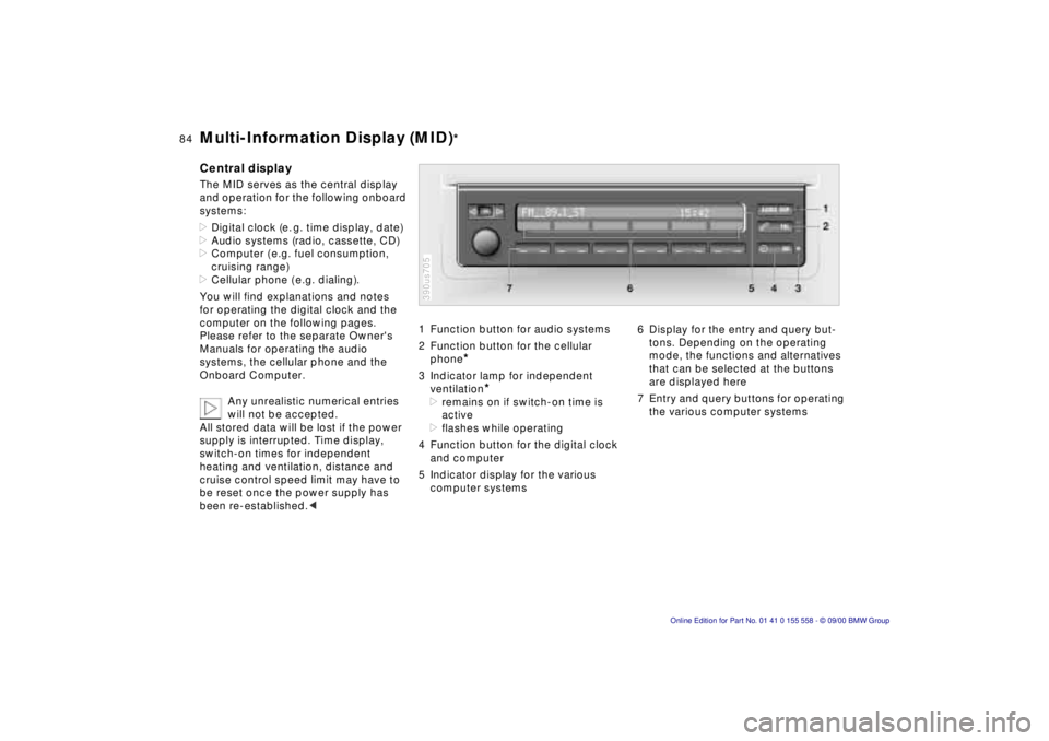
Central displayThe MID serves as the central display
and operation for the following onboard
systems:
>Digital clock (e. g. time display, date)
>Audio systems (radio, cassette, CD)
>Computer ( e.g. fuel consumption,
cruising range)
>Cellular phone ( e.g. dialing).
You will find explanations and notes
for operating the digital clock and the
computer on the following pages.
Please refer to the separate Owner's
Manuals for operating the audio
systems, the cellular phone and the
Onboard Computer.
Any unrealistic numerical entries
will not be accepted.
All stored data will be lost if the power
supply is interrupted. Time display,
switch-on times for independent
heating and ventilation, distance and
cruise control speed limit may have to
be reset once the power supply has
been re-established.<
1 Function button for audio systems
2 Function button for the cellular
phone
*
3 Indicator lamp for independent
ventilation
*
>remains on if switch-on time is
active
>flashes while operating
4 Function button for the digital clock
and computer
5 Indicator display for the various
computer systems390us705
6 Display for the entry and query but-
tons. Depending on the operating
mode, the functions and alternatives
that can be selected at the buttons
are displayed here
7 Entry and query buttons for operating
the various computer systems
Page 85 of 223
IndexDataTechnologyRepairsCar careControlsOverview
85n
Digital clock in the MID
*
Only make inputs when the vehi-
cle is standing still – to avoid
endangering yourself or other road
users.<
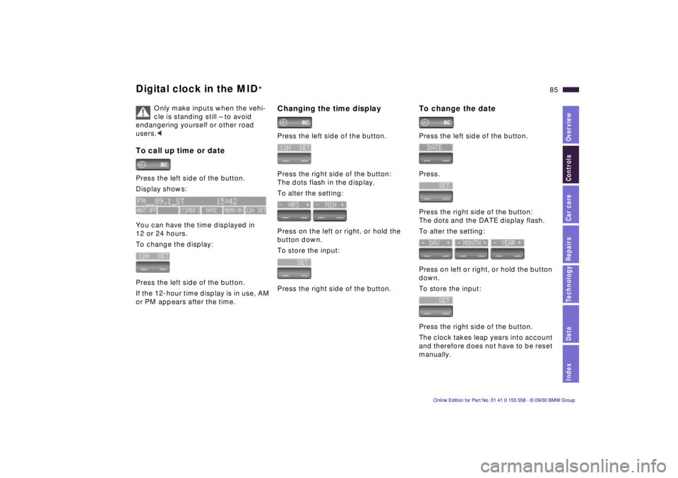
To call up time or datePress the left side of the button.
Display shows:
You can have the time displayed in
12 or 24 hours.
To change the display:
Press the left side of the button.
If the 12-hour time display is in use, AM
or PM appears after the time.
Changing the time displayPress the left side of the button.
Press the right side of the button:
The dots flash in the display.
To alter the setting:
Press on the left or right, or hold the
button down.
To store the input:
Press the right side of the button.
To change the datePress the left side of the button.
Press.
Press the right side of the button:
The dots and the DATE display flash.
To alter the setting:
Press on left or right, or hold the button
down.
To store the input:
Press the right side of the button.
The clock takes leap years into account
and therefore does not have to be reset
manually.
Page 86 of 223
86n
Digital clock in the MID
*
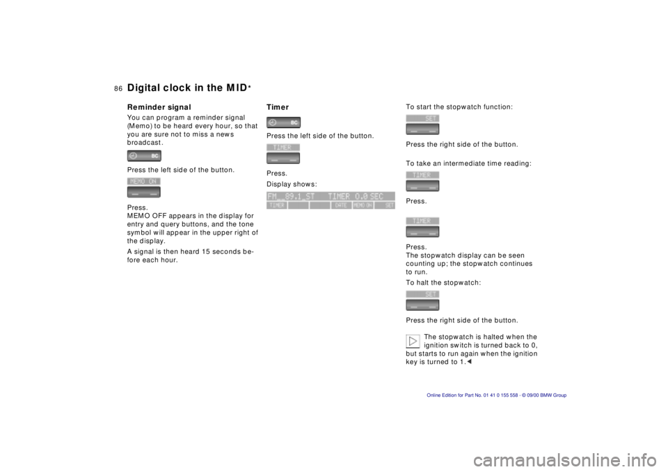
Reminder signalYou can program a reminder signal
(Memo) to be heard every hour, so that
you are sure not to miss a news
broadcast .
Press the left side of the button.
Press.
MEMO OFF appears in the display for
entry and query buttons, and the tone
symbol will appear in the upper right of
the display.
A signal is then heard 15 seconds be-
fore each hour.
Timer Press the left side of the button.
Press.
Display shows:
To start the stopwatch function:
Press the right side of the button.
To take an intermediate time reading:
Press.
Press.
The stopwatch display can be seen
counting up; the stopwatch continues
to run.
To halt the stopwatch:
Press the right side of the button.
The stopwatch is halted when the
ignition switch is turned back to 0,
but starts to run again when the ignition
key is turned to 1.<
Page 87 of 223
IndexDataTechnologyRepairsCar careControlsOverview
87n
Digital clock in the MID
*
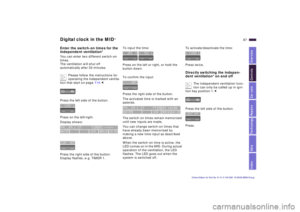
Enter the switch-on times for the
independent ventilation*You can enter two different switch-on
times.
The ventilation will shut off
automatically after 30 minutes.
Please follow the instructions for
operating the independent ventila-
tion that start on page 114.<
Press the left side of the button.
Press on the left/right.
Display shows:
Press the right side of the button:
Display flashes, e. g. TIMER 1.
To input the time:
Press on the left or right, or hold the
button down.
To confirm the input:
Press the right side of the button.
The activated time is marked with an
asterisk.
The switch-on times remain memorized
until new inputs are made.
You can change switch-on times that
have already been memorized by
making a new time input as described
above.
When the switch-on time is active, the
LED comes on in the MID. During actual
operation of the ventilation, the LED
flashes. The LED goes out when the
system is switched off.
To activate/deactivate the time:
Press twice.Directly switching the indepen-
dent ventilation* on and off
The independent ventilation func-
tion can only be called up in igni-
tion key position 1.<
Press the left side of the button.
Press.
Page 102 of 223
102n
Air conditioner Suggestions for your personal
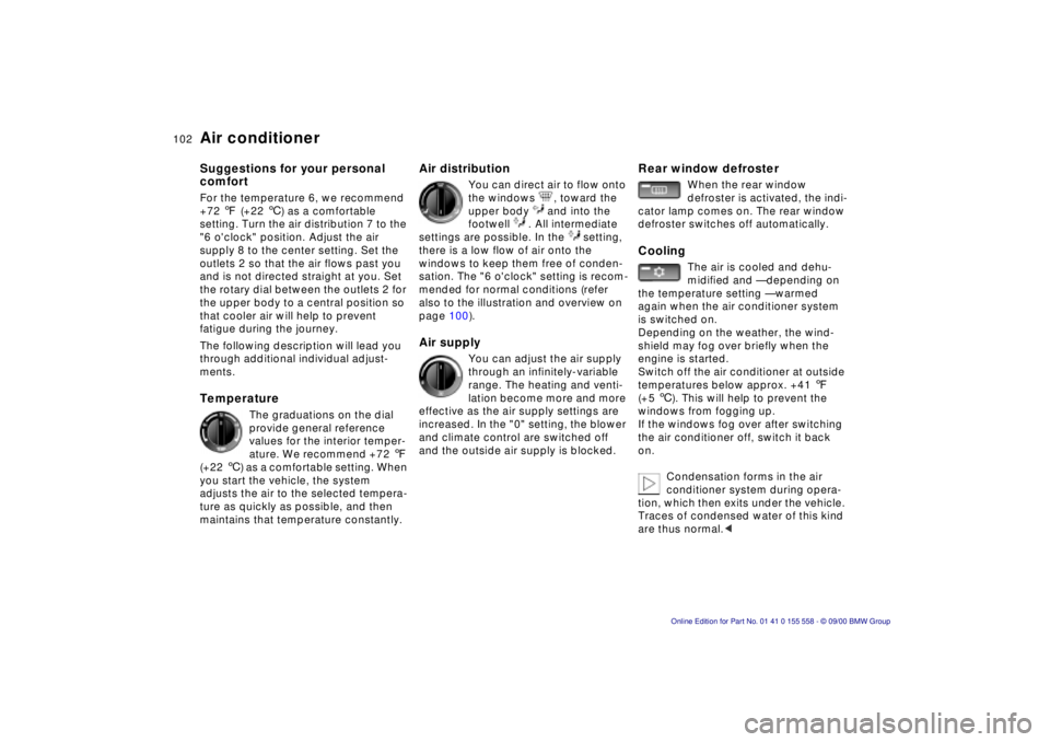
comfortFor the temperature 6, we recommend
+72 7 (+22 6) as a comfortable
setting. Turn the air distribution 7 to the
"6 o'clock" position. Adjust the air
supply 8 to the center setting. Set the
outlets 2 so that the air flows past you
and is not directed straight at you. Set
the rotary dial between the outlets 2 for
the upper body to a central position so
that cooler air will help to prevent
fatigue during the journey.
The following description will lead you
through additional individual adjust-
ments.Temperature
The graduations on the dial
provide general reference
values for the interior temper-
ature. We recommend +72 7
(+22 6) as a comfortable setting. When
you start the vehicle, the system
adjusts the air to the selected tempera-
ture as quickly as possible, and then
maintains that temperature constantly.
Air distribution
You can direct air to flow onto
the windows , toward the
upper body and into the
footwell . All intermediate
settings are possible. In the setting,
there is a low flow of air onto the
windows to keep them free of conden-
sation. The "6 o'clock" setting is recom-
mended for normal conditions (refer
also to the illustration and overview on
page 100).
Air supply
You can adjust the air supply
through an infinitely-variable
range. The heating and venti-
lation become more and more
effective as the air supply settings are
increased. In the "0" setting, the blower
and climate control are switched off
and the outside air supply is blocked.
Rear window defroster
When the rear window
defroster is activated, the indi-
cator lamp comes on. The rear window
defroster switches off automatically.
Cooling
The air is cooled and dehu-
midified and — depending on
the temperature setting — warmed
again when the air conditioner system
is switched on.
Depending on the weather, the wind-
shield may fog over briefly when the
engine is started.
Switch off the air conditioner at outside
temperatures below approx. +41 7
(+5 6). This will help to prevent the
windows from fogging up.
If the windows fog over after switching
the air conditioner off, switch it back
on.
Condensation forms in the air
conditioner system during opera-
tion, which then exits under the vehicle.
Traces of condensed water of this kind
are thus normal.<
Page 160 of 223
160n
Coolant
Do not add coolant to the cooling
system when the engine is hot. If
you attempt to do so, escaping coolant
can cause burns.
To avoid the possibility of damage later
on, never use anything other than
factory-approved, nitrite and amino-
free extended-duty antifreeze with
corrosion inhibitor. Your BMW center is
familiar with the factory specifications.
Antifreeze and anticorrosion agents are
hazardous to health. You should always
store them in their original container
and in a location which is inaccessible
to children.
Extended-duty antifreeze with corro-
sion inhibitor contains the flammable
substance ethylene–glycol. For this
reason, do not spill antifreeze with
corrosion inhibitor on hot engine parts.
It could ignite and cause serious
burns.<
Comply with the applicable envi-
ronmental laws regulating the
disposal of extended-duty antifreeze
with corrosion inhibitor.<
Checking coolant levelCorrect coolant level when the engine
is cold approx. +68 7(+20 6):
Unscrew the cap from the expansion
tank.
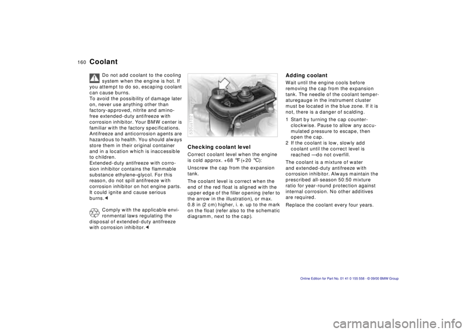
The coolant level is correct when the
end of the red float is aligned with the
upper edge of the filler opening (refer to
the arrow in the illustration), or max.
0.8 in (2 cm) higher, i. e. up to the mark
on the float (refer also to the schematic
diagramm, next to the cap).530us102
Adding coolant Wait until the engine cools before
removing the cap from the expansion
tank. The needle of the coolant temper-
aturegauge in the instrument cluster
must be located in the blue zone. If it is
not, there is a danger of scalding.
1 Start by turning the cap counter-
clockwise. Pause to allow any accu-
mulated pressure to escape, then
open the cap.
2 If the coolant is low, slowly add
coolant until the correct level is
reached — do not overfill.
The coolant is a mixture of water
and extended-duty antifreeze with
corrosion inhibitor. Always maintain the
prescribed all-season 50:50 mixture
ratio for year-round protection against
internal corrosion. No other additives
are required.
Replace the coolant every four years.