Page 30 BMW X5 3.0Si 2010 E70 Workshop Manual
[x] Cancel search | Manufacturer: BMW, Model Year: 2010, Model line: X5 3.0Si, Model: BMW X5 3.0Si 2010 E70Pages: 300, PDF Size: 12.41 MB
Page 87 of 300
Controls
85Reference
At a glance
Driving tips
Communications
Navigation
Entertainment
Mobility
>Off: LED goes out.
If Top View is displayed, switch o n the rea r vie w
camera using iDrive, refer to page87.
Optical warning
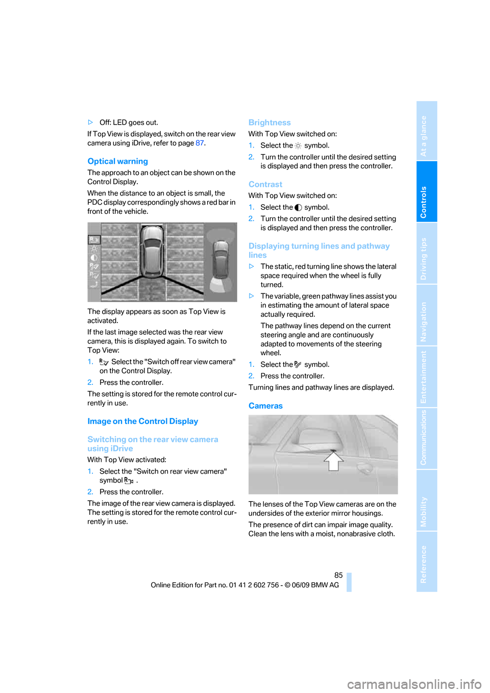
The approach to an object can be shown on the
Control Display.
When the distance to an object is small, the
PDC display correspondingly shows a red bar in
front of the vehicle.
The display appears as soon as Top View is
activated.
If the last image selected was the rear view
camera, this is displayed again. To switch to
Top View:
1.Select the "Switch off rear view camera"
on the Control Display.
2.Press the controller.
The setting is stored for the remote control cur-
rently in use.
Image on the Control Display
Switching on the rear view camera
using iDrive
With Top View activated:
1.Select the "Switch on rear view camera"
symbol .
2.Press the controller.
The image of the rear view camera is displayed.
The setting is stored for the remote control cur-
rently in use.
Brightness
With Top View switched on:
1.Select the symbol.
2.Turn the controller until the desired setting
is displayed and then press the controller.
Contrast
With Top View switched on:
1.Select the symbol.
2.Turn the controller until the desired setting
is displayed and then press the controller.
Displaying turning lines and pathway
lines
>The static, red turning line shows the lateral
space required when the wheel is fully
turned.
>The variable, green pathway lines assist you
in estimating the amount of lateral space
actually required.
The pathway lines depend on the current
steering angle and are continuously
adapted to movements of the steering
wheel.
1.Select the symbol.
2.Press the controller.
Turning lines and pathway lines are displayed.
Cameras
The lenses of the Top View cameras are on the
undersides of the exterior mirror housings.
The presence of dirt can impair image quality.
Clean the lens with a moist, nonabrasive cloth.
ba8_e70ag.book Seite 85 Freitag, 5. Juni 2009 11:42 11
Page 88 of 300
Technology for comfort, convenience and safety
86
Rear view camera*
The concept
The rear view camera assists you when parking
and maneuvering in reverse. To accomplish
this, the region behind your vehicle is shown on
the Control Display.
System limitations
Also make a direct visual check of the
traffic situation around the vehicle. Other-
wise, there could be a risk of accident, for exam-
ple due to other road users or objects outside
the image range of the rear view camera.<
The rear view camera is not able to detect
objects at greater heights or protruding
objects such as projections from walls.<
Automatic activation
With the engine running or the ignition switched
on, shift the selector lever into position R.
The image of the rear view camera is displayed
when the system has been switched on using
iDrive.
Automatic deactivation
The system switches off and the LED goes out:
>after approx. 33 ft/10 m when driving for-
ward
>at speeds over approx. 9 mph/15 km/h
when driving forward
Switch the system back on as needed.
Switching on/off manually
Press the button.
>On: LED lights up.>Off: LED goes out.
If PDC is displayed, switch on the rear view
camera using iDrive, refer to page83.
Assistance functions
Function requirements
>Rear view camera is switched on.
>Liftgate is completely closed.
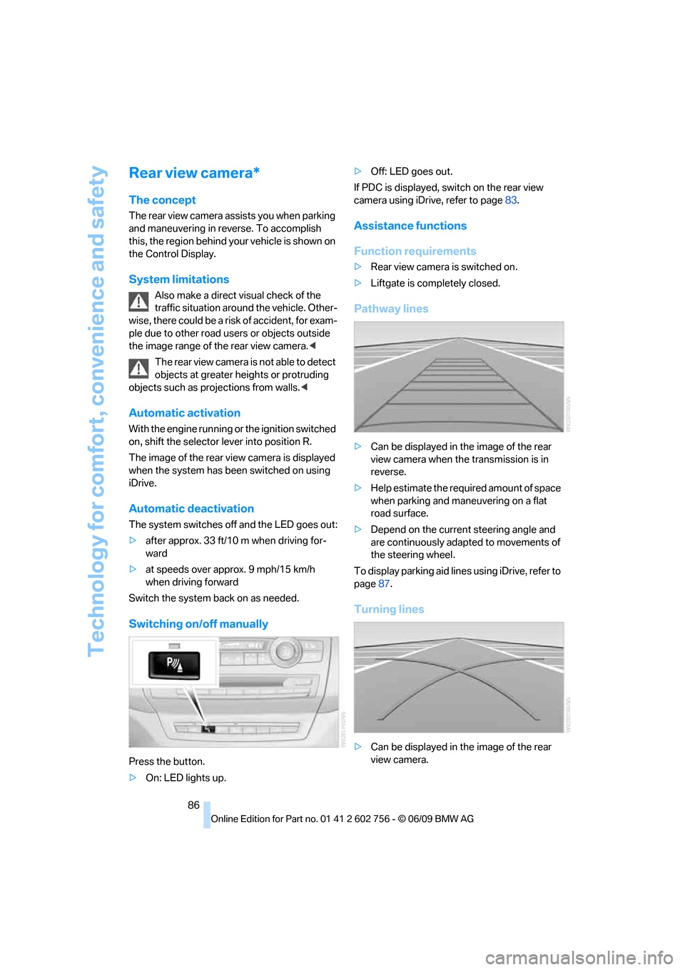
Pathway lines
>Can be displayed in the image of the rear
view camera when the transmission is in
reverse.
>Help estimate the required amount of space
when parking and maneuvering on a flat
road surface.
>Depend on the current steering angle and
are continuously adapted to movements of
the steering wheel.
To display parking aid lines using iDrive, refer to
page87.
Turning lines
>Can be displayed in the image of the rear
view camera.
ba8_e70ag.book Seite 86 Freitag, 5. Juni 2009 11:42 11
Page 89 of 300
Controls
87Reference
At a glance
Driving tips
Communications
Navigation
Entertainment
Mobility
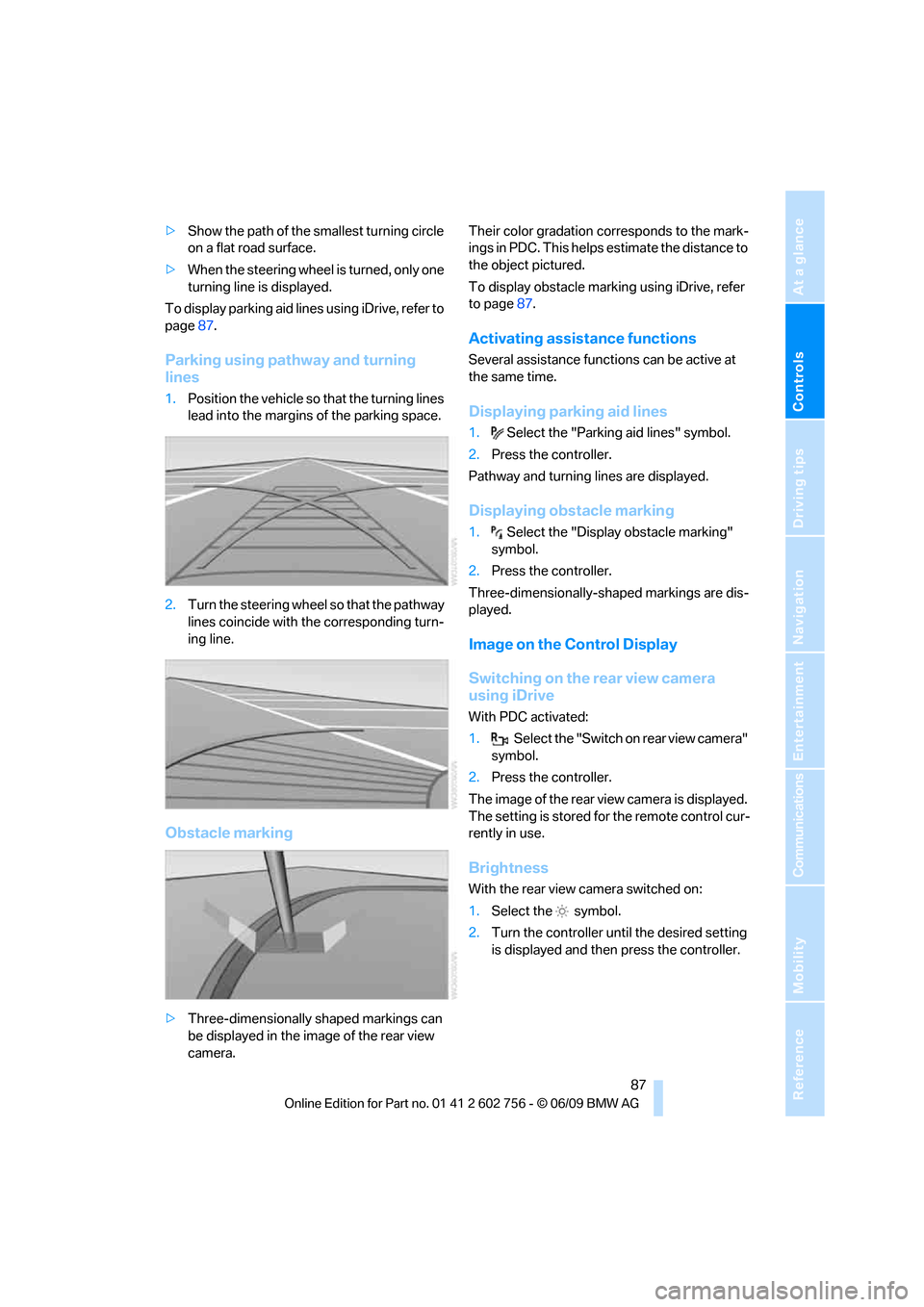
>Show the path of the smallest turning circle
on a flat road surface.
>When the steering wheel is turned, only one
turning line is displayed.
To display parking aid lines using iDrive, refer to
page87.
Parking using pathway and turning
lines
1.Position the vehicle so that the turning lines
lead into the margins of the parking space.
2.Turn the steering wheel so that the pathway
lines coincide with the corresponding turn-
ing line.
Obstacle marking
>Three-dimensionally shaped markings can
be displayed in the image of the rear view
camera.Their color gradation corresponds to the mark-
ings in PDC. This helps estimate the distance to
the object pictured.
To display obstacle marking using iDrive, refer
to page87.
Activating assistance functions
Several assistance functions can be active at
the same time.
Displaying parking aid lines
1.Select the "Parking aid lines" symbol.
2.Press the controller.
Pathway and turning lines are displayed.
Displaying obstacle marking
1.Select the "Display obstacle marking"
symbol.
2.Press the controller.
Three-dimensionally-shaped markings are dis-
played.
Image on the Control Display
Switching on the rear view camera
using iDrive
With PDC activated:
1.Select the "Switch on rear view camera"
symbol.
2.Press the controller.
The image of the rear view camera is displayed.
The setting is stored for the remote control cur-
rently in use.
Brightness
With the rear view camera switched on:
1.Select the symbol.
2.Turn the controller until the desired setting
is displayed and then press the controller.
ba8_e70ag.book Seite 87 Freitag, 5. Juni 2009 11:42 11
Page 90 of 300
Technology for comfort, convenience and safety
88
Contrast
With the rear view camera switched on:
1.Select the symbol.
2.Turn the controller until the desired setting
is displayed and then press the controller.
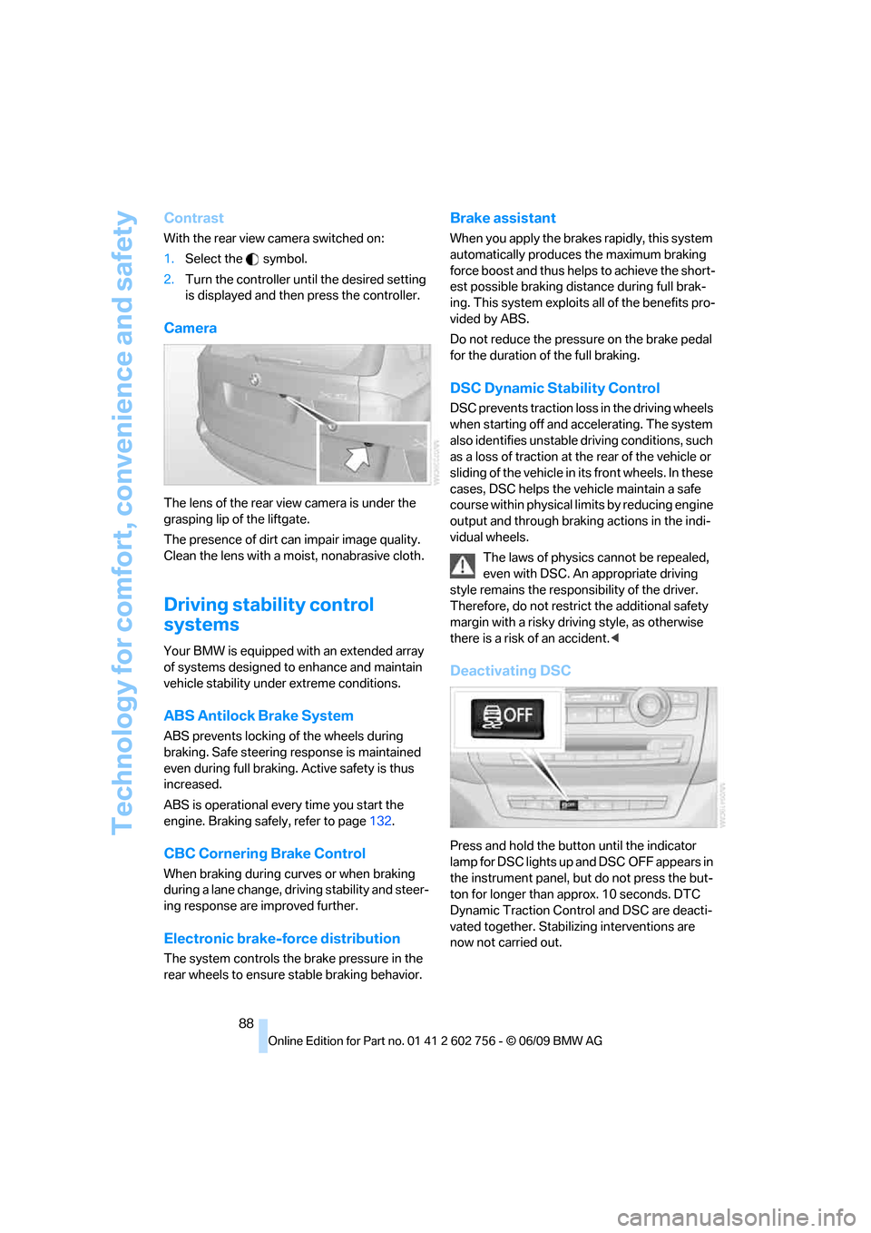
Camera
The lens of the rear view camera is under the
grasping lip of the liftgate.
The presence of dirt can impair image quality.
Clean the lens with a moist, nonabrasive cloth.
Driving stability control
systems
Your BMW is equipped with an extended array
of systems designed to enhance and maintain
vehicle stability under extreme conditions.
ABS Antilock Brake System
ABS prevents locking of the wheels during
braking. Safe steering response is maintained
even during full braking. Active safety is thus
increased.
ABS is operational every time you start the
engine. Braking safely, refer to page132.
CBC Cornering Brake Control
When braking during curves or when braking
during a lane change, driving stability and steer-
ing response are improved further.
Electronic brake-force distribution
The system controls the brake pressure in the
rear wheels to ensure stable braking behavior.
Brake assistant
When you apply the brakes rapidly, this system
automatically produces the maximum braking
force boost and thus helps to achieve the short-
est possible braking distance during full brak-
ing. This system exploits all of the benefits pro-
vided by ABS.
Do not reduce the pressure on the brake pedal
for the duration of the full braking.
DSC Dynamic Stability Control
DSC prevents traction loss in the driving wheels
when starting off and accelerating. The system
also identifies unstable driving conditions, such
as a loss of traction at the rear of the vehicle or
sliding of the vehicle in its front wheels. In these
cases, DSC helps the vehicle maintain a safe
course within physical limits by reducing engine
output and through braking actions in the indi-
vidual wheels.
The laws of physics cannot be repealed,
even with DSC. An appropriate driving
style remains the responsibility of the driver.
Therefore, do not restrict the additional safety
margin with a risky driving style, as otherwise
there is a risk of an accident.<
Deactivating DSC
Press and hold the button until the indicator
lamp for DSC lights up and DSC OFF appears in
the instrument panel, but do not press the but-
ton for longer than approx. 10 seconds. DTC
Dynamic Traction Control and DSC are deacti-
vated together. Stabilizing interventions are
now not carried out.
ba8_e70ag.book Seite 88 Freitag, 5. Juni 2009 11:42 11
Page 92 of 300
Technology for comfort, convenience and safety
90
xDrive
xDrive is the 4-wheel drive system of your
BMW. The combined effects of xDrive and DSC
further optimize the traction and dynamic driv-
ing characteristics. The 4-wheel drive system
xDrive variably distributes the drive forces to
the front and rear axle depending on the driving
situation and prevailing road conditions.
Dynamic Performance Control*
The concept
Dynamic Performance Control optimizes the
handling characteristics of your BMW when
starting off, cornering, and during evasive
maneuvers. To achieve this, the system variably
distributes the drive torque of the rear axle to
the two rear wheels. This further increases the
steering precision and tracking stability of your
vehicle.
Display
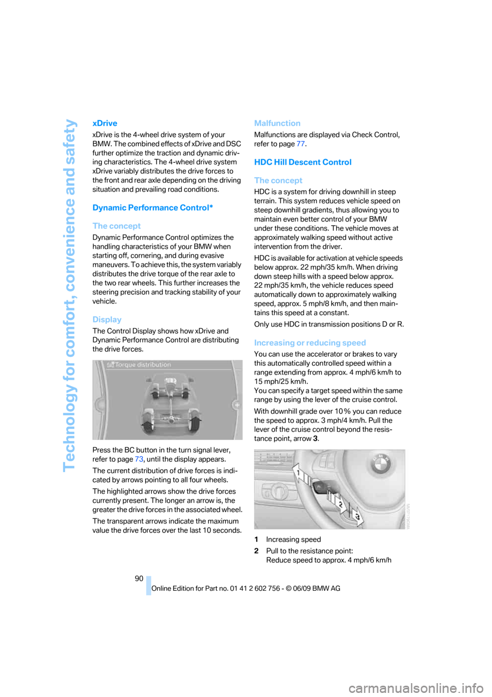
The Control Display shows how xDrive and
Dynamic Performance Control are distributing
the drive forces.
Press the BC button in the turn signal lever,
refer to page73, until the display appears.
The current distribution of drive forces is indi-
cated by arrows pointing to all four wheels.
The highlighted arrows show the drive forces
currently present. The longer an arrow is, the
greater the drive forces in the associated wheel.
The transparent arrows indicate the maximum
value the drive forces over the last 10 seconds.
Malfunction
Malfunctions are displayed via Check Control,
refer to page77.
HDC Hill Descent Control
The concept
HDC is a system for driving downhill in steep
terrain. This system reduces vehicle speed on
steep downhill gradients, thus allowing you to
maintain even better control of your BMW
under these conditions. The vehicle moves at
approximately walking speed without active
intervention from the driver.
HDC is available for activation at vehicle speeds
below approx. 22 mph/35 km/h. When driving
down steep hills with a speed below approx.
22 mph/35 km/h, the vehicle reduces speed
automatically down to approximately walking
speed, approx. 5 mph/8 km/h, and then main-
tains this speed at a constant.
Only use HDC in transmission positions D or R.
Increasing or reducing speed
You can use the accelerator or brakes to vary
this automatically controlled speed within a
range extending from approx. 4 mph/6 km/h to
15 mph/25 km/h.
You can specify a target speed within the same
range by using the lever of the cruise control.
With downhill grade over 10Ξ you can reduce
the speed to approx. 3mph/4km/h. Pull the
lever of the cruise control beyond the resis-
tance point, arrow3.
1Increasing speed
2Pull to the resistance point:
Reduce speed to approx. 4 mph/6 km/h
ba8_e70ag.book Seite 90 Freitag, 5. Juni 2009 11:42 11
Page 94 of 300
Technology for comfort, convenience and safety
92
Selecting chassis and suspension
tuning
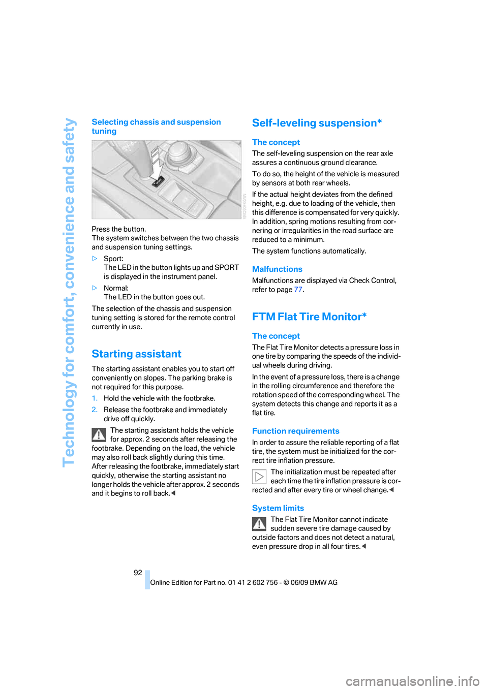
Press the button.
The system switches between the two chassis
and suspension tuning settings.
>Sport:
The LED in the button lights up and SPORT
is displayed in the instrument panel.
>Normal:
The LED in the button goes out.
The selection of the chassis and suspension
tuning setting is stored for the remote control
currently in use.
Starting assistant
The starting assistant enables you to start off
conveniently on slopes. The parking brake is
not required for this purpose.
1.Hold the vehicle with the footbrake.
2.Release the footbrake and immediately
drive off quickly.
The starting assistant holds the vehicle
for approx. 2 seconds after releasing the
footbrake. Depending on the load, the vehicle
may also roll back slightly during this time.
After releasing the footbrake, immediately start
quickly, otherwise the starting assistant no
longer holds the vehicle after approx. 2 seconds
and it begins to roll back.<
Self-leveling suspension*
The concept
The self-leveling suspension on the rear axle
assures a continuous ground clearance.
To do so, the height of the vehicle is measured
by sensors at both rear wheels.
If the actual height deviates from the defined
height, e.g. due to loading of the vehicle, then
this difference is compensated for very quickly.
In addition, spring motions resulting from cor-
nering or irregularities in the road surface are
reduced to a minimum.
The system functions automatically.
Malfunctions
Malfunctions are displayed via Check Control,
refer to page77.
FTM Flat Tire Monitor*
The concept
The Flat Tire Monitor detects a pressure loss in
one tire by comparing the speeds of the individ-
ual wheels during driving.
In the event of a pressure loss, there is a change
in the rolling circumference and therefore the
rotation speed of the corresponding wheel. The
system detects this change and reports it as a
flat tire.
Function requirements
In order to assure the reliable reporting of a flat
tire, the system must be initialized for the cor-
rect tire inflation pressure.
The initialization must be repeated after
each time the tire inflation pressure is cor-
rected and after every tire or wheel change.<
System limits
The Flat Tire Monitor cannot indicate
sudden severe tire damage caused by
outside factors and does not detect a natural,
even pressure drop in all four tires.<
ba8_e70ag.book Seite 92 Freitag, 5. Juni 2009 11:42 11
Page 95 of 300
Controls
93Reference
At a glance
Driving tips
Communications
Navigation
Entertainment
Mobility
In the following situations, the system could be
delayed or malfunction:
>System has not been initialized
>Driving on snowy or slippery road surface
>Sporty driving style: slip in the drive wheels,
high lateral acceleration
>Driving with snow chains
*
When you are driving with the compact wheel*
the Flat Tire Monitor is unable to function.
Initializing system
The initialization finishes during driving,
which can be interrupted at any time.
When driving resumes, the initialization is con-
tinued automatically. Do not initialize the sys-
tem when driving with snow chains
* or with the
compact wheel
*.<
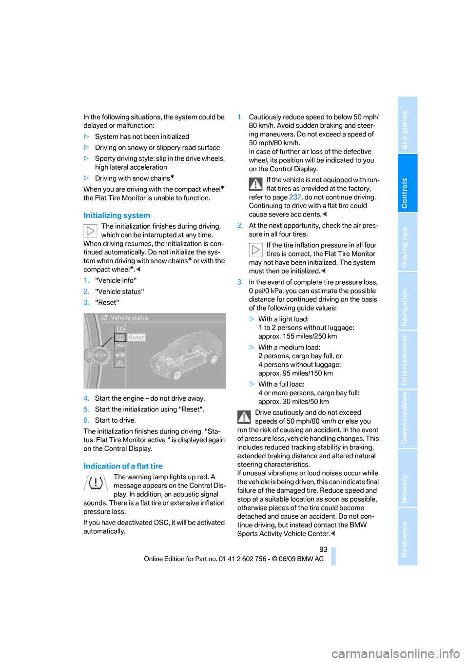
1."Vehicle Info"
2."Vehicle status"
3."Reset"
4.Start the engine – do not drive away.
5.Start the initialization using "Reset".
6.Start to drive.
The initialization finishes during driving. "Sta-
tus: Flat Tire Monitor active " is displayed again
on the Control Display.
Indication of a flat tire
The warning lamp lights up red. A
message appears on the Control Dis-
play. In addition, an acoustic signal
sounds. There is a flat tire or extensive inflation
pressure loss.
If you have deactivated DSC, it will be activated
automatically.1.Cautiously reduce speed to below 50 mph/
80 km/h. Avoid sudden braking and steer-
ing maneuvers. Do not exceed a speed of
50 mph/80 km/h.
In case of further air loss of the defective
wheel, its position will be indicated to you
on the Control Display.
If the vehicle is not equipped with run-
flat tires as provided at the factory,
refer to page237, do not continue driving.
Continuing to drive with a flat tire could
cause severe accidents.<
2.At the next opportunity, check the air pres-
sure in all four tires.
If the tire inflation pressure in all four
tires is correct, the Flat Tire Monitor
may not have been initialized. The system
must then be initialized.<
3.In the event of complete tire pressure loss,
0 psi/0 kPa, you can estimate the possible
distance for continued driving on the basis
of the following guide values:
>With a light load:
1 to 2 persons without luggage:
approx. 155 miles/250 km
>With a medium load:
2 persons, cargo bay full, or
4 persons without luggage:
approx. 95 miles/150 km
>With a full load:
4 or more persons, cargo bay full:
approx. 30 miles/50 km
Drive cautiously and do not exceed
speeds of 50 mph/80 km/h or else you
run the risk of causing an accident. In the event
of pressure loss, vehicle handling changes. This
includes reduced tracking stability in braking,
extended braking distance and altered natural
steering characteristics.
If unusual vibrations or loud noises occur while
the vehicle is being driven, this can indicate final
failure of the damaged tire. Reduce speed and
stop at a suitable location as soon as possible,
otherwise pieces of the tire could become
detached and cause an accident. Do not con-
tinue driving, but instead contact the BMW
Sports Activity Vehicle Center.<
ba8_e70ag.book Seite 93 Freitag, 5. Juni 2009 11:42 11
Page 97 of 300
Controls
95Reference
At a glance
Driving tips
Communications
Navigation
Entertainment
Mobility
Do not reset the system when driving with a
compact wheel
*.
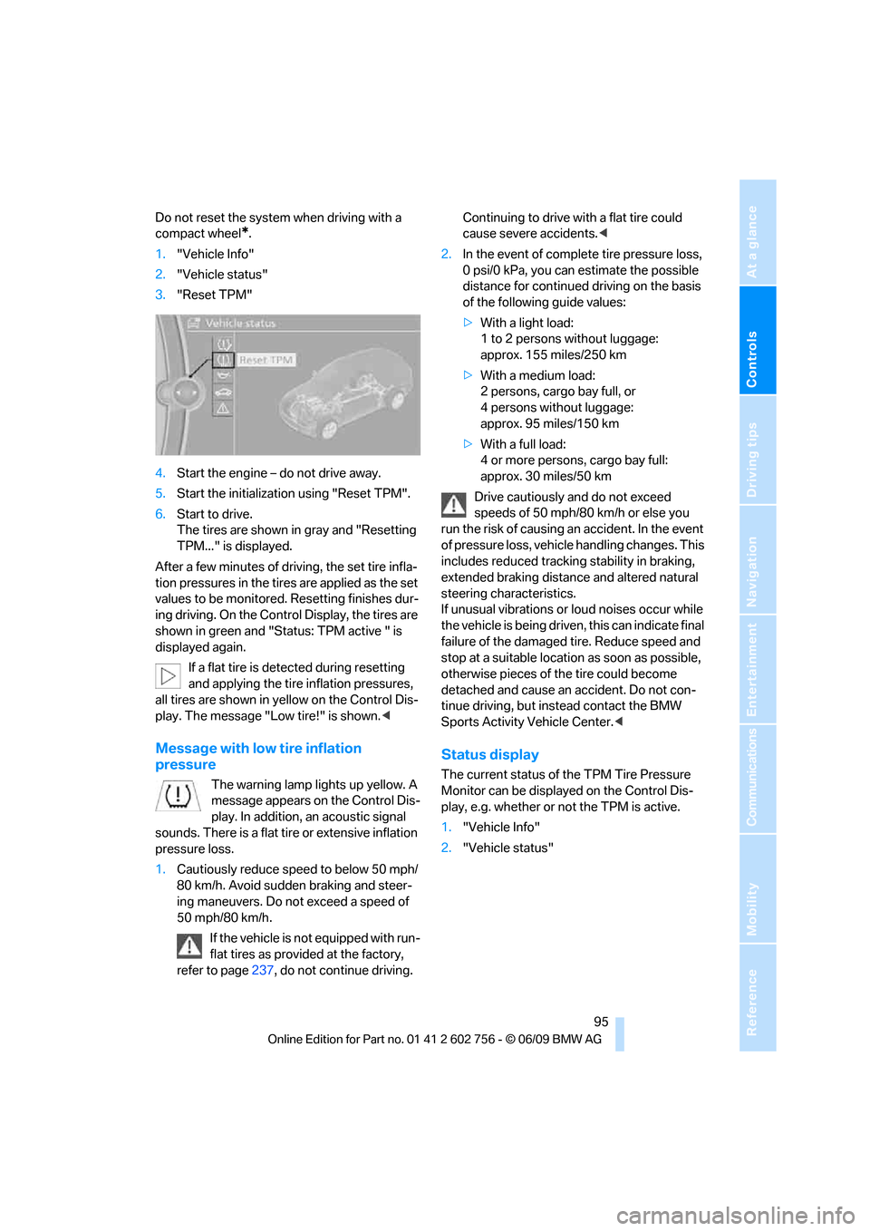
1."Vehicle Info"
2."Vehicle status"
3."Reset TPM"
4.Start the engine – do not drive away.
5.Start the initialization using "Reset TPM".
6.Start to drive.
The tires are shown in gray and "Resetting
TPM..." is displayed.
After a few minutes of driving, the set tire infla-
tion pressures in the tires are applied as the set
values to be monitored. Resetting finishes dur-
ing driving. On the Control Display, the tires are
shown in green and "Status: TPM active " is
displayed again.
If a flat tire is detected during resetting
and applying the tire inflation pressures,
all tires are shown in yellow on the Control Dis-
play. The message "Low tire!" is shown.<
Message with low tire inflation
pressure
The warning lamp lights up yellow. A
message appears on the Control Dis-
play. In addition, an acoustic signal
sounds. There is a flat tire or extensive inflation
pressure loss.
1.Cautiously reduce speed to below 50 mph/
80 km/h. Avoid sudden braking and steer-
ing maneuvers. Do not exceed a speed of
50 mph/80 km/h.
If the vehicle is not equipped with run-
flat tires as provided at the factory,
refer to page237, do not continue driving. Continuing to drive with a flat tire could
cause severe accidents.<
2.In the event of complete tire pressure loss,
0 psi/0 kPa, you can estimate the possible
distance for continued driving on the basis
of the following guide values:
>With a light load:
1 to 2 persons without luggage:
approx. 155 miles/250 km
>With a medium load:
2 persons, cargo bay full, or
4 persons without luggage:
approx. 95 miles/150 km
>With a full load:
4 or more persons, cargo bay full:
approx. 30 miles/50 km
Drive cautiously and do not exceed
speeds of 50 mph/80 km/h or else you
run the risk of causing an accident. In the event
of pressure loss, vehicle handling changes. This
includes reduced tracking stability in braking,
extended braking distance and altered natural
steering characteristics.
If unusual vibrations or loud noises occur while
the vehicle is being driven, this can indicate final
failure of the damaged tire. Reduce speed and
stop at a suitable location as soon as possible,
otherwise pieces of the tire could become
detached and cause an accident. Do not con-
tinue driving, but instead contact the BMW
Sports Activity Vehicle Center.<
Status display
The current status of the TPM Tire Pressure
Monitor can be displayed on the Control Dis-
play, e.g. whether or not the TPM is active.
1."Vehicle Info"
2."Vehicle status"
ba8_e70ag.book Seite 95 Freitag, 5. Juni 2009 11:42 11
Page 100 of 300
Technology for comfort, convenience and safety
98
Airbags
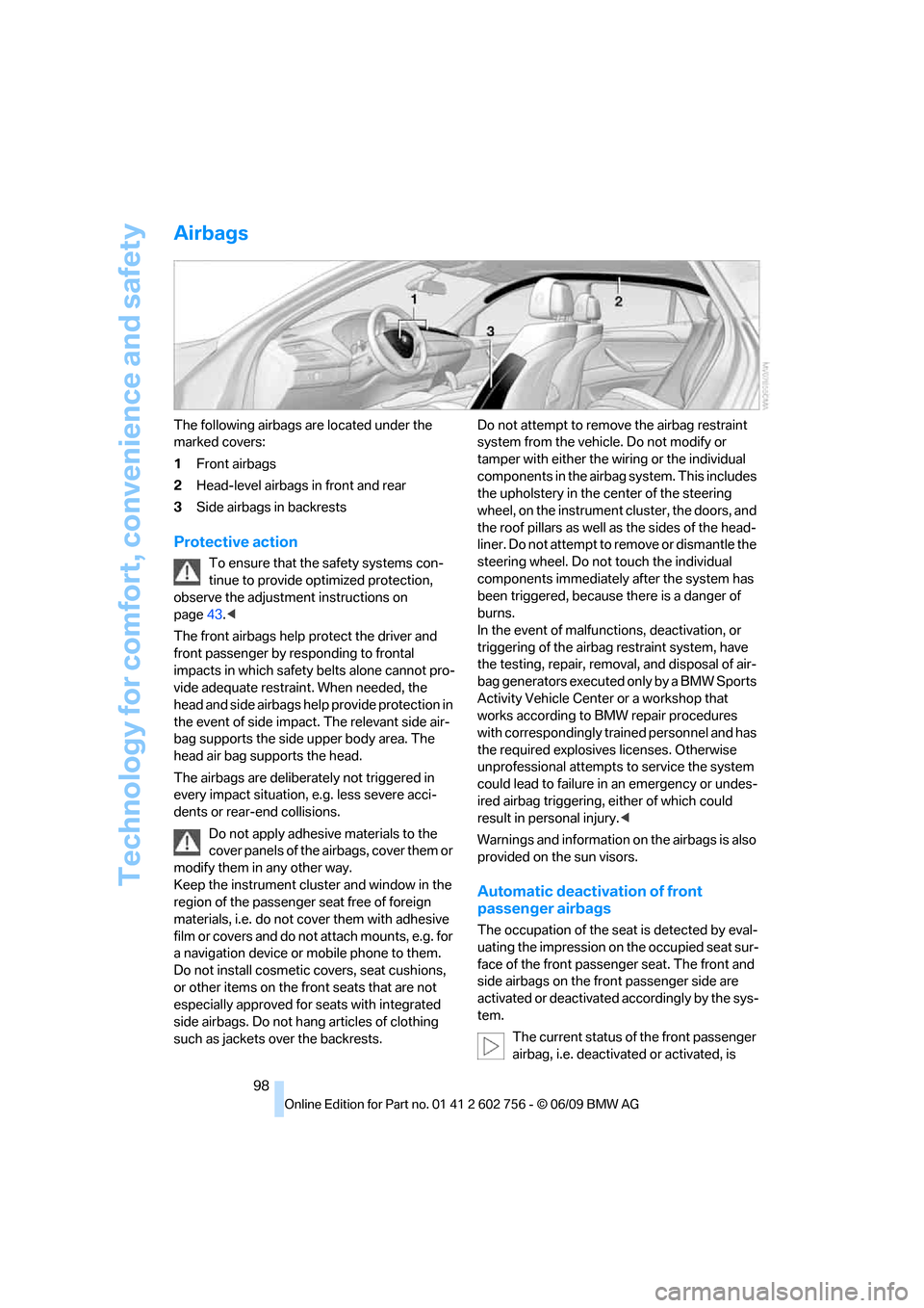
The following airbags are located under the
marked covers:
1Front airbags
2Head-level airbags in front and rear
3Side airbags in backrests
Protective action
To ensure that the safety systems con-
tinue to provide optimized protection,
observe the adjustment instructions on
page43.<
The front airbags help protect the driver and
front passenger by responding to frontal
impacts in which safety belts alone cannot pro-
vide adequate restraint. When needed, the
head and side airbags help provide protection in
the event of side impact. The relevant side air-
bag supports the side upper body area. The
head air bag supports the head.
The airbags are deliberately not triggered in
every impact situation, e.g. less severe acci-
dents or rear-end collisions.
Do not apply adhesive materials to the
cover panels of the airbags, cover them or
modify them in any other way.
Keep the instrument cluster and window in the
region of the passenger seat free of foreign
materials, i.e. do not cover them with adhesive
film or covers and do not attach mounts, e.g. for
a navigation device or mobile phone to them.
Do not install cosmetic covers, seat cushions,
or other items on the front seats that are not
especially approved for seats with integrated
side airbags. Do not hang articles of clothing
such as jackets over the backrests.Do not attempt to remove the airbag restraint
system from the vehicle. Do not modify or
tamper with either the wiring or the individual
components in the airbag system. This includes
the upholstery in the center of the steering
wheel, on the instrument cluster, the doors, and
the roof pillars as well as the sides of the head-
liner. Do not attempt to remove or dismantle the
steering wheel. Do not touch the individual
components immediately after the system has
been triggered, because there is a danger of
burns.
In the event of malfunctions, deactivation, or
triggering of the airbag restraint system, have
the testing, repair, removal, and disposal of air-
bag generators executed only by a BMW Sports
Activity Vehicle Center or a workshop that
works according to BMW repair procedures
with correspondingly trained personnel and has
the required explosives licenses. Otherwise
unprofessional attempts to service the system
could lead to failure in an emergency or undes-
ired airbag triggering, either of which could
result in personal injury.<
Warnings and information on the airbags is also
provided on the sun visors.
Automatic deactivation of front
passenger airbags
The occupation of the seat is detected by eval-
uating the impression on the occupied seat sur-
face of the front passenger seat. The front and
side airbags on the front passenger side are
activated or deactivated accordingly by the sys-
tem.
The current status of the front passenger
airbag, i.e. deactivated or activated, is
ba8_e70ag.book Seite 98 Freitag, 5. Juni 2009 11:42 11
Page 101 of 300
Controls
99Reference
At a glance
Driving tips
Communications
Navigation
Entertainment
Mobility
indicated by the indicator lamp over the interior
rearview mirror, refer to Operating state of front
passenger airbags in the following.<
Before transporting a child on the front
passenger seat, read the safety informa-
tion and follow the instructions under Trans-
porting children safely, refer to page55.
When teenagers and adults assume certain sit-
ting positions, this can cause the front and side
airbags to deactivate. The indicator lamp for the
front passenger airbags lights up when this
occurs. In these cases, change the sitting posi-
tion so that the front passenger airbags are acti-
vated and the indicator lamp goes out. If the
desired status cannot be produced by changing
the sitting position, transport the correspond-
ing person on the rear seat. Do not fit seat cov-
ers, seat cushion padding, ball mats or other
items onto the front passenger seat unless they
are specifically recommended by BMW. Do not
lay objects under the seat which could press
against the seat from below. Otherwise a cor-
rect evaluation of the occupied seat surface
cannot be ensured.<
Operating state of front passenger
airbags
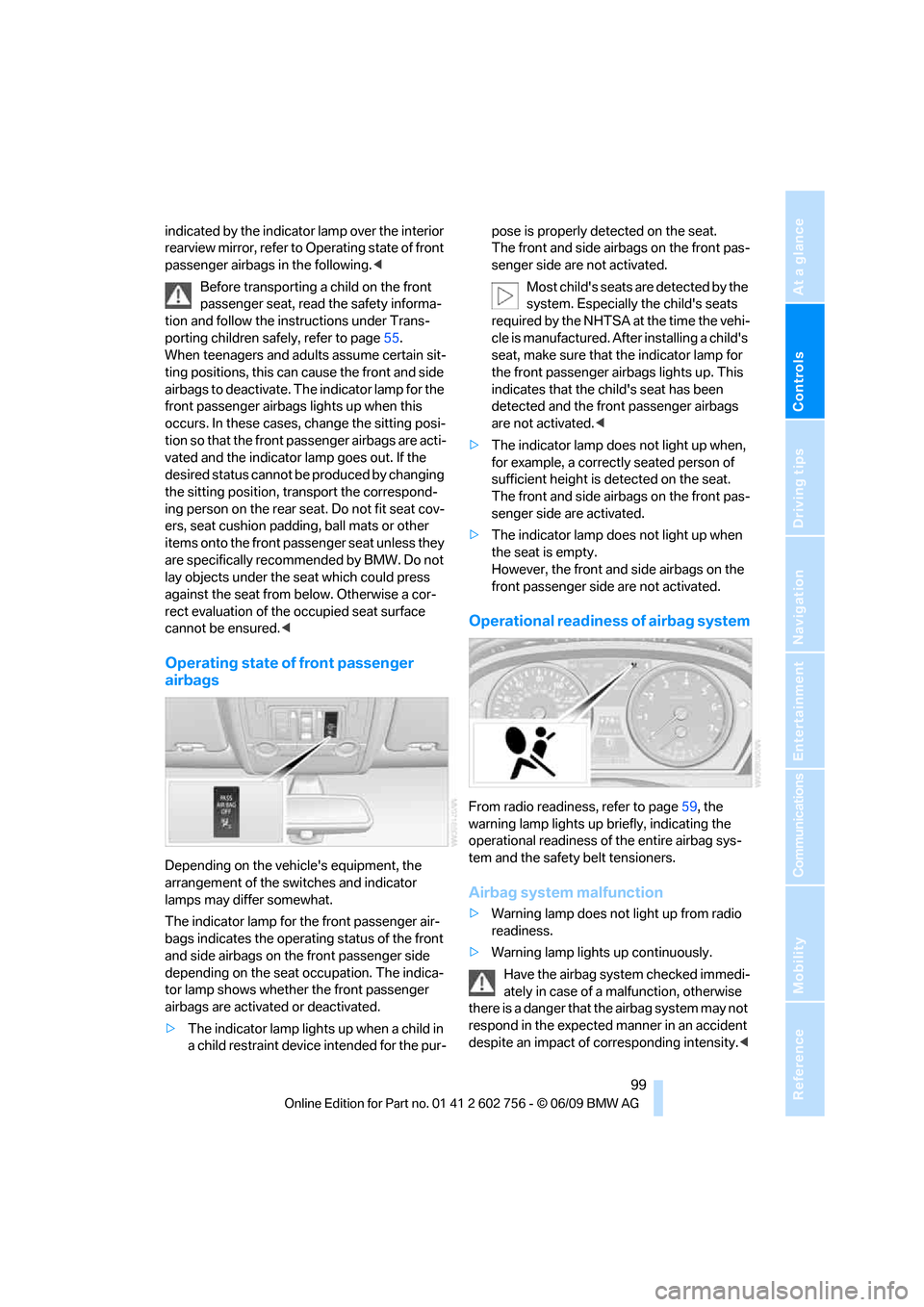
Depending on the vehicle's equipment, the
arrangement of the switches and indicator
lamps may differ somewhat.
The indicator lamp for the front passenger air-
bags indicates the operating status of the front
and side airbags on the front passenger side
depending on the seat occupation. The indica-
tor lamp shows whether the front passenger
airbags are activated or deactivated.
>The indicator lamp lights up when a child in
a child restraint device intended for the pur-pose is properly detected on the seat.
The front and side airbags on the front pas-
senger side are not activated.
Most child's seats are detected by the
system. Especially the child's seats
required by the NHTSA at the time the vehi-
cle is manufactured. After installing a child's
seat, make sure that the indicator lamp for
the front passenger airbags lights up. This
indicates that the child's seat has been
detected and the front passenger airbags
are not activated.<
>The indicator lamp does not light up when,
for example, a correctly seated person of
sufficient height is detected on the seat.
The front and side airbags on the front pas-
senger side are activated.
>The indicator lamp does not light up when
the seat is empty.
However, the front and side airbags on the
front passenger side are not activated.
Operational readiness of airbag system
From radio readiness, refer to page59, the
warning lamp lights up briefly, indicating the
operational readiness of the entire airbag sys-
tem and the safety belt tensioners.
Airbag system malfunction
>Warning lamp does not light up from radio
readiness.
>Warning lamp lights up continuously.
Have the airbag system checked immedi-
ately in case of a malfunction, otherwise
there is a danger that the airbag system may not
respond in the expected manner in an accident
despite an impact of corresponding intensity.<
ba8_e70ag.book Seite 99 Freitag, 5. Juni 2009 11:42 11