ESP BMW X5 4.8I 2007 E70 Owner's Guide
[x] Cancel search | Manufacturer: BMW, Model Year: 2007, Model line: X5 4.8I, Model: BMW X5 4.8I 2007 E70Pages: 272, PDF Size: 9.03 MB
Page 72 of 272
Everything under control
70 >Average speed
>Average fuel consumption
Resetting values
You can reset the values for the average speed
and average fuel consumption:
1.Select the respective menu item and press
the controller.
2.To confirm your selection, press the con-
troller again.
Entering a distance manually
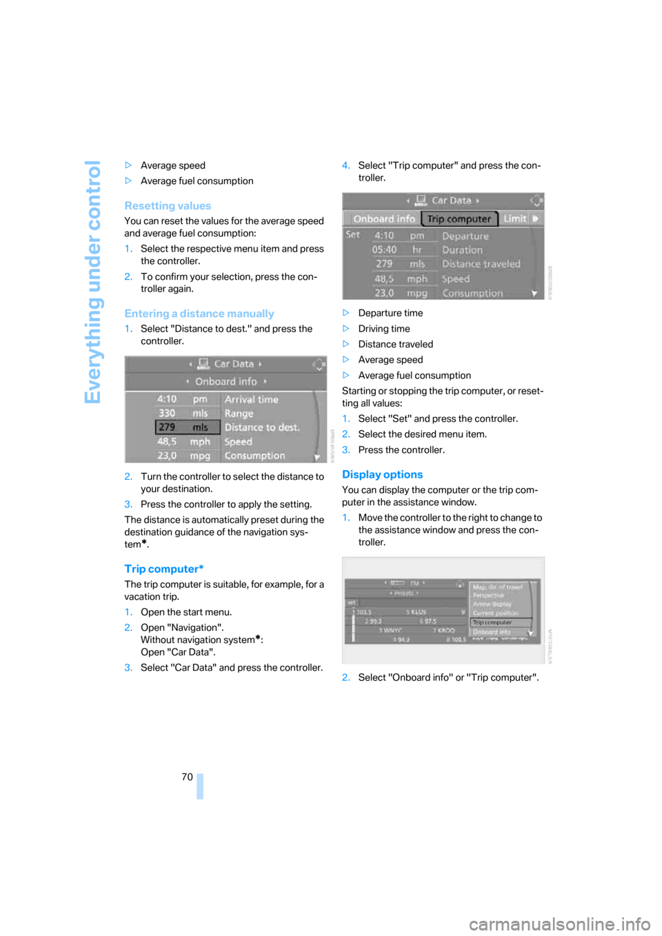
1.Select "Distance to dest." and press the
controller.
2.Turn the controller to select the distance to
your destination.
3.Press the controller to apply the setting.
The distance is automatically preset during the
destination guidance of the navigation sys-
tem
*.
Trip computer*
The trip computer is suitable, for example, for a
vacation trip.
1.Open the start menu.
2.Open "Navigation".
Without navigation system
*:
Open "Car Data".
3.Select "Car Data" and press the controller.4.Select "Trip computer" and press the con-
troller.
>Departure time
>Driving time
>Distance traveled
>Average speed
>Average fuel consumption
Starting or stopping the trip computer, or reset-
ting all values:
1.Select "Set" and press the controller.
2.Select the desired menu item.
3.Press the controller.
Display options
You can display the computer or the trip com-
puter in the assistance window.
1.Move the controller to the right to change to
the assistance window and press the con-
troller.
2.Select "Onboard info" or "Trip computer".
Page 76 of 272
Everything under control
74
Check Control
The concept
The Check Control monitors functions in the
vehicle and issues a message if there is a mal-
function in the monitored systems. This kind of
Check Control message consists of indicator
and warning lamps in the instrument cluster,
and if necessary an acoustic signal and text
messages at the bottom of the Control Display.
Indicator and warning lamps
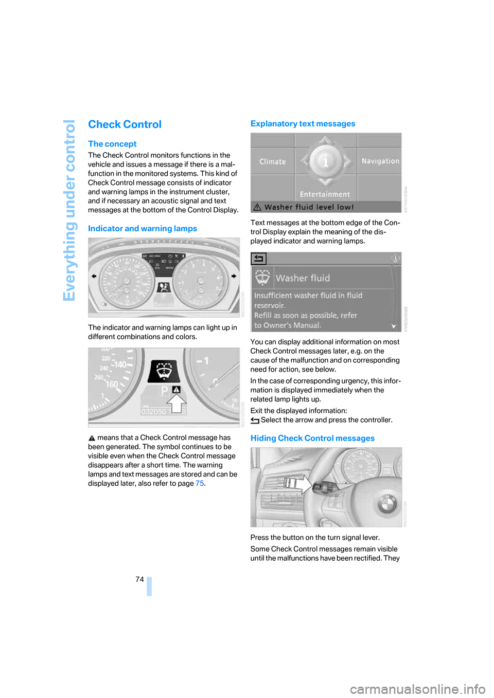
The indicator and warning lamps can light up in
different combinations and colors.
means that a Check Control message has
been generated. The symbol continues to be
visible even when the Check Control message
disappears after a short time. The warning
lamps and text messages are stored and can be
displayed later, also refer to page75.
Explanatory text messages
Text messages at the bottom edge of the Con-
trol Display explain the meaning of the dis-
played indicator and warning lamps.
You can display additional information on most
Check Control messages later, e.g. on the
cause of the malfunction and on corresponding
need for action, see below.
In the case of corresponding urgency, this infor-
mation is displayed immediately when the
related lamp lights up.
Exit the displayed information:
Select the arrow and press the controller.
Hiding Check Control messages
Press the button on the turn signal lever.
Some Check Control messages remain visible
until the malfunctions have been rectified. They
Page 83 of 272
Controls
81Reference
At a glance
Driving tips
Communications
Navigation
Entertainment
Mobility
PDC with visual warning*
You can also have the system show distances
to objects on the Control Display. Objects that
are farther away are already shown there before
a signal tone sounds.
The setting is stored for the remote control cur-
rently in use.
If the vehicle is equipped with a backup camera,
refer to the display of the backup camera on
page83.
iDrive, for explanation of concept, refer to
page16.
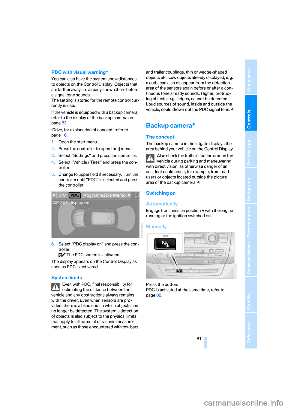
1.Open the start menu.
2.Press the controller to open the menu.
3.Select "Settings" and press the controller.
4.Select "Vehicle / Tires" and press the con-
troller.
5.Change to upper field if necessary. Turn the
controller until "PDC" is selected and press
the controller.
6.Select "PDC display on" and press the con-
troller.
The PDC screen is activated.
The display appears on the Control Display as
soon as PDC is activated.
System limits
Even with PDC, final responsibility for
estimating the distance between the
vehicle and any obstructions always remains
with the driver. Even when sensors are pro-
vided, there is a blind spot in which objects can
no longer be detected. The system's detection
of objects is also subject to the physical limits
that apply to all forms of ultrasonic measure-
ment, such as those encountered with tow bars and trailer couplings, thin or wedge-shaped
objects etc. Low objects already displayed, e. g.
a curb, can also disappear from the detection
area of the sensors again before or after a con-
tinuous tone already sounds. Higher, protrud-
ing objects, e.g. ledges, cannot be detected.
Loud sources of sound, inside and outside the
vehicle, could drown out the PDC signal tone.<
Backup camera*
The concept
The backup camera in the liftgate displays the
area behind your vehicle on the Control Display.
Also check the traffic situation around the
vehicle during parking and maneuvering
with direct vision, as otherwise danger of an
accident could result, for example, from road
users or objects located outside the picture
area of the backup camera.<
Switching on
Automatically
Engage transmission position R with the engine
running or the ignition switched on.
Manually
Press the button.
PDC is activated at the same time, refer to
page80.
Page 84 of 272
Technology for comfort, convenience and safety
82
Switching off
Automatically
When driving forward from a speed of approx.
12 mph/20 km/h or from a driven distance of
approx. 164 ft/50 m.
Manually
Press the button again; the LED goes out.
Driver assistance functions
The following functions can improve the effect
of the backup camera depending on the situa-
tion.
They can only be activated when the tailgates
are completely closed.
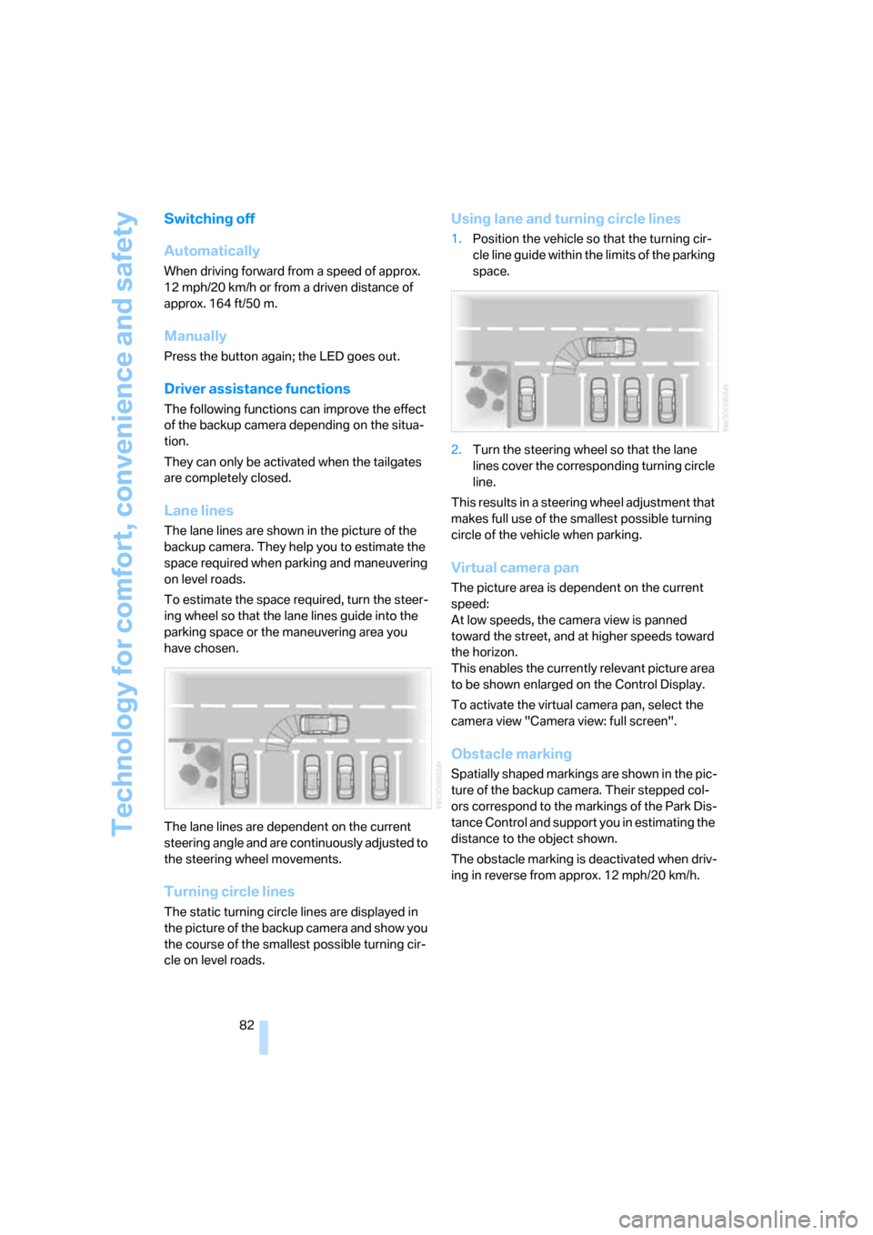
Lane lines
The lane lines are shown in the picture of the
backup camera. They help you to estimate the
space required when parking and maneuvering
on level roads.
To estimate the space required, turn the steer-
ing wheel so that the lane lines guide into the
parking space or the maneuvering area you
have chosen.
The lane lines are dependent on the current
steering angle and are continuously adjusted to
the steering wheel movements.
Turning circle lines
The static turning circle lines are displayed in
the picture of the backup camera and show you
the course of the smallest possible turning cir-
cle on level roads.
Using lane and turning circle lines
1.Position the vehicle so that the turning cir-
cle line guide within the limits of the parking
space.
2.Turn the steering wheel so that the lane
lines cover the corresponding turning circle
line.
This results in a steering wheel adjustment that
makes full use of the smallest possible turning
circle of the vehicle when parking.
Virtual camera pan
The picture area is dependent on the current
speed:
At low speeds, the camera view is panned
toward the street, and at higher speeds toward
the horizon.
This enables the currently relevant picture area
to be shown enlarged on the Control Display.
To activate the virtual camera pan, select the
camera view "Camera view: full screen".
Obstacle marking
Spatially shaped markings are shown in the pic-
ture of the backup camera. Their stepped col-
ors correspond to the markings of the Park Dis-
tance Control and support you in estimating the
distance to the object shown.
The obstacle marking is deactivated when driv-
ing in reverse from approx. 12 mph/20 km/h.
Page 86 of 272
Technology for comfort, convenience and safety
84
Driving stability control
systems
Your BMW is equipped with an extended array
of systems designed to enhance and maintain
vehicle stability under extreme conditions.
ABS Antilock Brake System
ABS prevents locking of the wheels during
braking. Safe steering response is maintained
even during full braking. Active safety is thus
increased.
ABS is operational every time you start the
engine. Braking safely, refer to page123.
CBC Cornering Brake Control
When braking during curves or when braking
during a lane change, driving stability and steer-
ing response are improved further.
Electronic brake-force distribution
The system controls the brake pressure in the
rear wheels to ensure stable braking behavior.
DBC Dynamic Brake Control
When you apply the brakes rapidly, this system
automatically produces the maximum braking
force boost and thus helps to achieve the short-
est possible braking distance during full brak-
ing. This system exploits all of the benefits pro-
vided by ABS.
Do not reduce the pressure on the brake pedal
for the duration of the full braking.
DSC Dynamic Stability Control
DSC prevents traction loss in the driving wheels
when starting off and accelerating. DSC also
identifies unstable driving conditions, such as a
loss of traction at the rear of the vehicle or slid-
ing of the vehicle in its front wheels. In these
cases, DSC helps the vehicle maintain a safe
course within physical limits by reducing engine
output and through braking actions in the indi-
vidual wheels.The laws of physics cannot be repealed,
even with DSC. An appropriate driving
style remains the responsibility of the driver.
Therefore, do not reduce the additional safety
margin further by taking risks.<
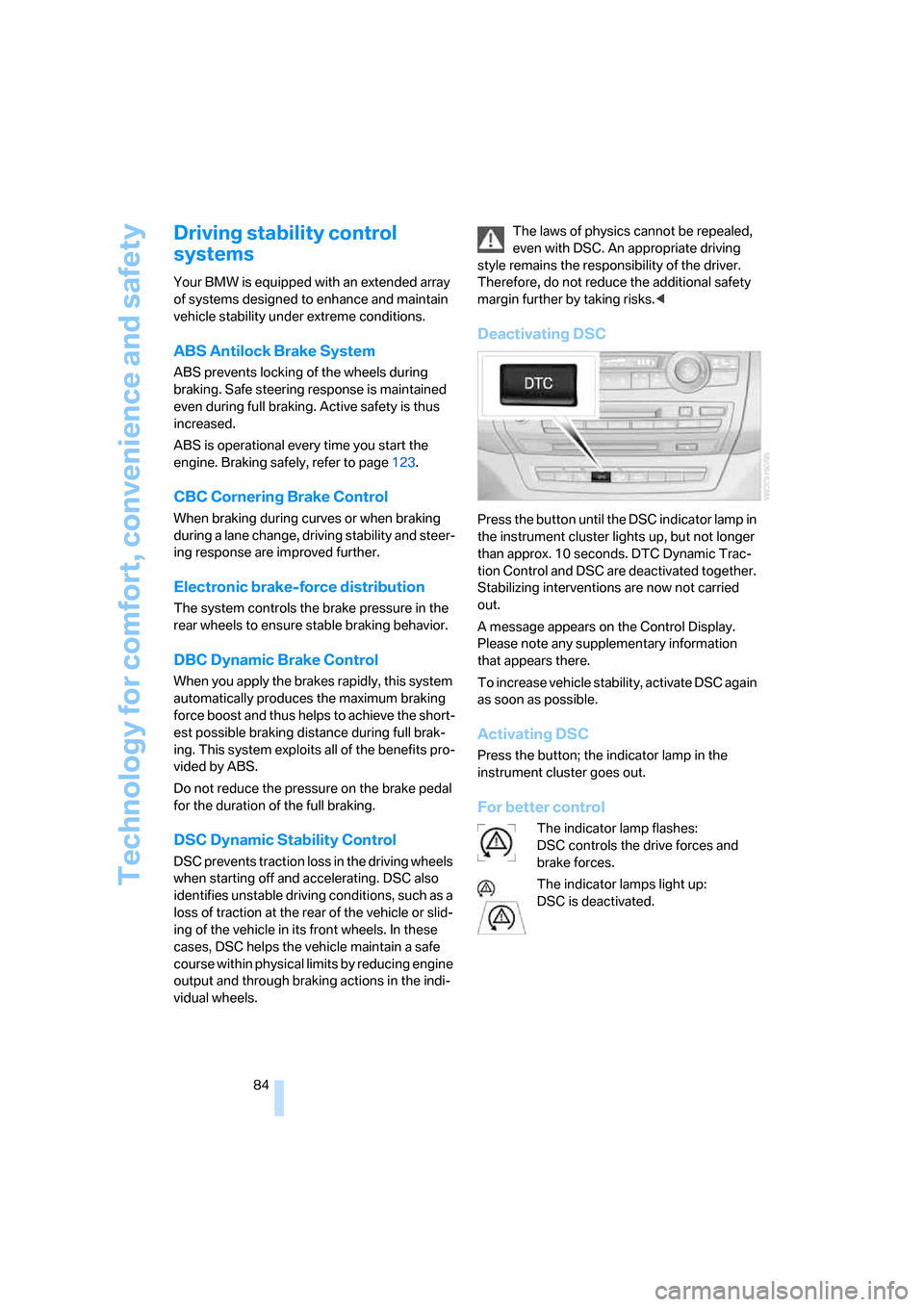
Deactivating DSC
Press the button until the DSC indicator lamp in
the instrument cluster lights up, but not longer
than approx. 10 seconds. DTC Dynamic Trac-
tion Control and DSC are deactivated together.
Stabilizing interventions are now not carried
out.
A message appears on the Control Display.
Please note any supplementary information
that appears there.
To increase vehicle stability, activate DSC again
as soon as possible.
Activating DSC
Press the button; the indicator lamp in the
instrument cluster goes out.
For better control
The indicator lamp flashes:
DSC controls the drive forces and
brake forces.
The indicator lamps light up:
DSC is deactivated.
Page 89 of 272
Controls
87Reference
At a glance
Driving tips
Communications
Navigation
Entertainment
Mobility
>Normal:
The LED in the button goes out.
The selection of the chassis and suspension
tuning setting is stored for the remote control
currently in use.
Self-leveling suspension*
Malfunction
The warning lamp for self-leveling
suspension lights up yellow and a
message is shown on the Control
Display. A malfunction has occurred in the self-
leveling suspension. Stop and check the vehi-
cle. If it is considerably lower at the rear than at
the front, and possibly also on one side – rear
left compared to rear right –, proceed to the
nearest BMW Sports Activity Vehicle Center or
a workshop that works according to BMW
repair procedures with correspondingly trained
personnel. Drive with appropriate caution in the
meantime. The vehicle has reduced ground
clearance and driving comfort may be notice-
ably reduced. Even if the orientation of the vehi-
cle is normal, when a malfunction is indicated
on the display, you should proceed to the near-
est BMW Sports Activity Vehicle Center or a
workshop that works according to BMW guide-
lines and uses appropriately trained personnel.
FTM Flat Tire Monitor*
The concept
The Flat Tire Monitor keeps track of the infla-
tion pressures in the tires as you drive. The sys-
tem provides an alert whenever the inflation
pressure drops significantly in relation to the
pressure in another tire.
In the event of a pressure loss, the rolling radius
and therefore the rotation speed of the wheels
change. This change is detected and is
reported as a flat tire.
Functional requirement
In order to assure the reliable reporting of a flat
tire, the system must be initialized for the cor-
rect tire inflation pressure.
The initialization must be repeated after
each time the tire inflation pressure is cor-
rected and after every tire or wheel change.<
System limits
The Flat Tire Monitor cannot indicate
sudden severe tire damage caused by
outside factors and does not detect a natural,
even pressure drop in all four tires.<
In the following situations, the system could be
delayed or malfunction:
>System has not been initialized
>Driving on snowy or slippery road surface
>Sporty driving style: slip in the drive wheels,
high lateral acceleration
>Driving with snow chains
*
When you are driving with the compact wheel*
the Flat Tire Monitor is unable to function.
Initializing system
The initialization finishes during driving,
which can be interrupted at any time.
When driving resumes, the initialization is con-
tinued automatically. Do not initialize the sys-
tem when driving with snow chains
* or with the
compact wheel
*.<
iDrive, for explanation of concept, refer to
page16.
1.Press the button.
This opens the start menu.
2.Press the controller to open the menu.
3.Select "Settings" and press the controller.
4.Select "Vehicle / Tires" and press the con-
troller.
Page 91 of 272
Controls
89Reference
At a glance
Driving tips
Communications
Navigation
Entertainment
Mobility
TPM Tire Pressure Monitor*
The concept
TPM checks the tire inflation pressure in the
four mounted tires. The system reports when
the tire inflation pressure has dropped consid-
erably in one or several tires.
Functional requirement
In order to assure the reliable reporting of a flat
tire, the system must have been reset with the
correct tire inflation pressure.
Always use wheels with TPM electronics, oth-
erwise fault-free operation of the system is not
ensured.
Reset the system again after each correc-
tion of the tire inflation pressure and after
every tire or wheel change.<
System limits
TPM cannot announce sudden serious
tire damage caused by external influ-
ences.<
The system does not function properly if it has
not been reset, e.g. a flat tire is reported despite
correct tire inflation pressures.
The system is inactive and cannot display a flat
tire if a wheel has been mounted without TPM
electronics, e.g. a compact wheel
*, or if TPM is
temporarily interfered with by other systems or
devices which use the same radio frequency.
Status display on Control Display
The tire and system status is indicated by the
color of the tires.
TPM takes the fact that the tire pressure
changes during driving into account. A correc-
tion is only required if requested by TPM with
the color.
Green
The tire pressure matches the learned set state.
"TPM active" is displayed on the Control Dis-
play.
One wheel is yellow
Flat tire or a major drop in inflation pressure in
the indicated tire. A message appears on the
Control Display.
All wheels are yellow
Flat tire or a major drop in inflation pressure in
several tires. A message appears on the Control
Display.
Gray
The system cannot detect a flat tire.
Reasons for this can be:
>TPM is being reset
>Temporary interference due to systems or
devices which use the same radio fre-
quency
>Malfunction
Resetting system
Reset the system again after each correc-
tion of the tire inflation pressure and after
every tire or wheel change.<
Resetting finishes during driving, which can be
interrupted at any time. When driving resumes,
resetting is continued automatically. Do not
reset the system when driving with a compact
wheel
*.
iDrive, for explanation of concept, refer to
page16.
1.Press the button.
This opens the start menu.
2.Press the controller to open the menu.
3.Select "Settings" and press the controller.
4.Select "Vehicle / Tires" and press the con-
troller.
Page 93 of 272
Controls
91Reference
At a glance
Driving tips
Communications
Navigation
Entertainment
Mobility
A message like this is displayed in the following
situations:
>In case of a malfunction:
Have the system checked
>If a wheel without TPM electronics is
mounted, e.g. a compact wheel
*
>If TPM is temporarily interfered with by
other systems or devices which use the
same radio frequency
Explanation according to the NHTSA/
FMVSS 138 Tire Pressure Monitoring
Systems
Each tire, including the spare*, should be
checked monthly when cold and inflated to the
inflation pressure recommended by the vehicle
manufacturer on the vehicle placard or tire infla-
tion pressure label. If your vehicle has tires of a
different size than the size indicated on the
vehicle placard or tire inflation pressure label,
you should determine the proper tire inflation
pressure for those tires. As an added safety fea-
ture, your vehicle has been equipped with a tire
pressure monitoring system, TPMS, that illumi-
nates a low tire pressure telltale when one or
more of your tires are significantly under-
inflated. Accordingly, when the low tire pres-
sure telltale illuminates, you should stop and
check your tires as soon as possible, and inflate
them to the proper pressure. Driving on a signif-
icantly underinflated tire causes the tire to over-
heat and can lead to tire failure. Under-inflation
also reduces fuel efficiency and tire tread life,
and may affect the vehicle's handling and stop-
ping ability. Please note that the TPMS is not a
substitute for proper tire maintenance, and it is
the driver's responsibility to maintain correct
tire pressure, even if under-inflation has not
reached the level to trigger illumination of the
TPMS low tire pressure telltale.
The TPMS malfunction indicator is combined
with the low tire pressure telltale. When the sys-
tem detects a malfunction, the telltale will flash
for approximately one minute and then remain
continuously illuminated. This sequence will
continue upon subsequent vehicle startups as
long as the malfunction exists. When the mal-function indicator is illuminated, the system
may not be able to detect or signal low tire pres-
sure as intended. TPMS malfunctions may
occur for a variety of reasons, including the
installation of replacement or alternate tires or
wheels on the vehicle that prevent the TPMS
from functioning properly. Always check the
TPMS malfunction telltale after replacing one or
more tires or wheels on your vehicle to ensure
that the replacement or alternate tires and
wheels allow the TPMS to continue to function
properly.Active steering*
The concept
The active steering actively varies the steering
angle of the front wheels in relation to the steer-
ing wheel movements. In addition, it also varies
the steering force required for steering depend-
ing on the vehicle's speed.
When you are driving in the low road speed
range, e. g. in a town or when parking, the steer-
ing angle increases, i.e. the steering becomes
very direct. In the higher speed range, on the
other hand, the steering angle is reduced more
and more. This improves the handling capability
of your BMW over the entire speed range.
In critical situations, the system can make tar-
geted corrections to the steering angle pro-
vided by the driver and thus stabilize the vehicle
before the driver intervenes.
Malfunction
The warning lamp lights up yellow
and a message is shown on the Con-
trol Display. The active steering is no
longer operational. At low speeds,
greater steering wheel movements are
required, whereas at higher speeds, the vehicle
reacts more sensitively to steering wheel move-
ments. The stability-promoting intervention
can also be deactivated. Proceed cautiously
and drive defensively. Have the system
checked.
Page 94 of 272
Technology for comfort, convenience and safety
92
Brake force display
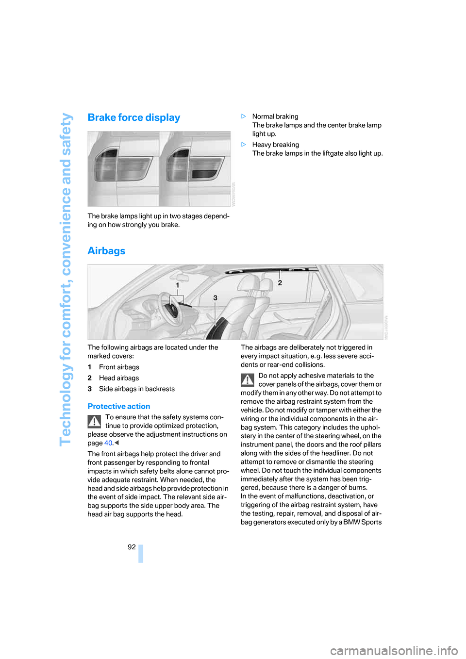
The brake lamps light up in two stages depend-
ing on how strongly you brake.>Normal braking
The brake lamps and the center brake lamp
light up.
>Heavy breaking
The brake lamps in the liftgate also light up.
Airbags
The following airbags are located under the
marked covers:
1Front airbags
2Head airbags
3Side airbags in backrests
Protective action
To ensure that the safety systems con-
tinue to provide optimized protection,
please observe the adjustment instructions on
page40.<
The front airbags help protect the driver and
front passenger by responding to frontal
impacts in which safety belts alone cannot pro-
vide adequate restraint. When needed, the
head and side airbags help provide protection in
the event of side impact. The relevant side air-
bag supports the side upper body area. The
head air bag supports the head.The airbags are deliberately not triggered in
every impact situation, e. g. less severe acci-
dents or rear-end collisions.
Do not apply adhesive materials to the
cover panels of the airbags, cover them or
modify them in any other way. Do not attempt to
remove the airbag restraint system from the
vehicle. Do not modify or tamper with either the
wiring or the individual components in the air-
bag system. This category includes the uphol-
stery in the center of the steering wheel, on the
instrument panel, the doors and the roof pillars
along with the sides of the headliner. Do not
attempt to remove or dismantle the steering
wheel. Do not touch the individual components
immediately after the system has been trig-
gered, because there is a danger of burns.
In the event of malfunctions, deactivation, or
triggering of the airbag restraint system, have
the testing, repair, removal, and disposal of air-
bag generators executed only by a BMW Sports
Page 95 of 272
Controls
93Reference
At a glance
Driving tips
Communications
Navigation
Entertainment
Mobility
Activity Vehicle Center or a workshop that
works according to BMW repair procedures
with correspondingly trained personnel and has
the required explosives licenses. Unprofes-
sional attempts to service the system could
lead to failure in an emergency or undesired air-
bag activation, either of which could result in
personal injury.<
Warnings and information on the airbags is also
provided on the sun visors.
Automatic deactivation of front
passenger airbags
The occupation of the seat is detected by eval-
uating the impression on the occupied seat sur-
face of the front passenger seat. The front and
side airbags on the front passenger side are
activated or deactivated accordingly by the sys-
tem.
The current status of the front passenger
airbags, i.e. deactivated or activated, is
indicated by the indicator lamp over the interior
rearview mirror, refer to Operating state of front
passenger airbags in the following.<
Before transporting a child on the front
passenger seat, observe the safety infor-
mation and handling instructions under Trans-
porting children safely, refer to page52.
The front and side airbags on the front passen-
ger side can be deactivated for teenagers and
adults in certain sitting positions; then the indi-
cator lamp for the front passenger airbags lights
up. In these cases, change the sitting position
so that the front passenger airbags are acti-
vated and the indicator lamp goes out. If the
desired status cannot be produced by changing
the sitting position, transport the correspond-
ing person on the rear seat. Do not fit seat cov-
ers, seat cushion padding, ball mats or other
items onto the front passenger seat unless they
are specifically recommended by BMW. Do not
lay objects under the seat which could press
against the seat from below. Otherwise a cor-
rect evaluation of the occupied seat surface
cannot be ensured.<
Operating state of front passenger
airbags
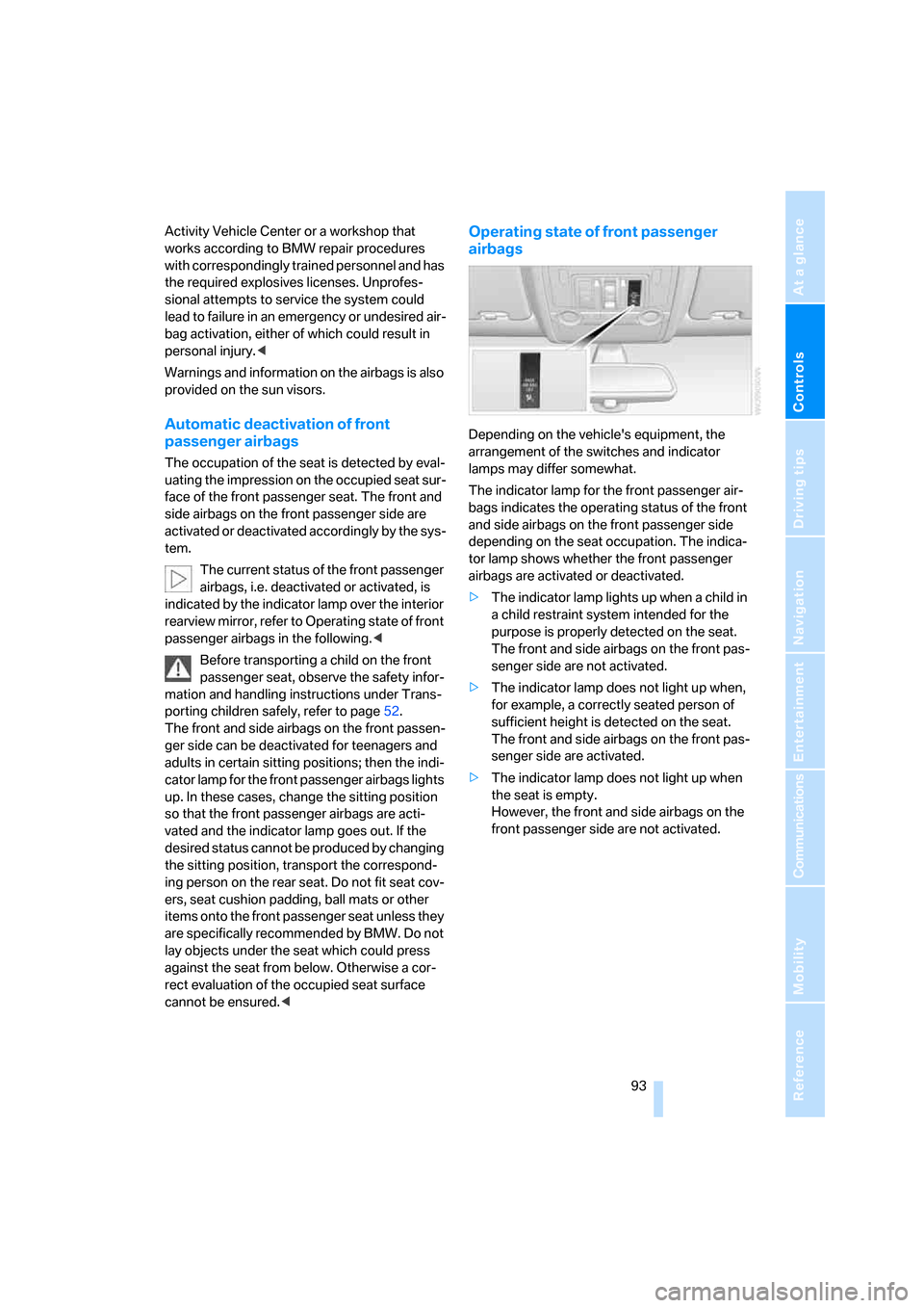
Depending on the vehicle's equipment, the
arrangement of the switches and indicator
lamps may differ somewhat.
The indicator lamp for the front passenger air-
bags indicates the operating status of the front
and side airbags on the front passenger side
depending on the seat occupation. The indica-
tor lamp shows whether the front passenger
airbags are activated or deactivated.
>The indicator lamp lights up when a child in
a child restraint system intended for the
purpose is properly detected on the seat.
The front and side airbags on the front pas-
senger side are not activated.
>The indicator lamp does not light up when,
for example, a correctly seated person of
sufficient height is detected on the seat.
The front and side airbags on the front pas-
senger side are activated.
>The indicator lamp does not light up when
the seat is empty.
However, the front and side airbags on the
front passenger side are not activated.