tailgate BMW X5 SDRIVE35I 2014 User Guide
[x] Cancel search | Manufacturer: BMW, Model Year: 2014, Model line: X5 SDRIVE35I, Model: BMW X5 SDRIVE35I 2014Pages: 265, PDF Size: 6.2 MB
Page 46 of 265
▷With Comfort Access: If you are carrying
the remote control with you, grasp the
driver side or front passenger side door
handle completely.
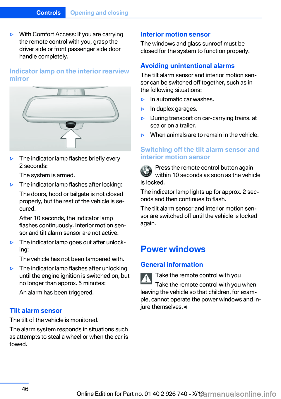
Indicator lamp on the interior rearview
mirror
▷The indicator lamp flashes briefly every
2 seconds:
The system is armed.▷The indicator lamp flashes after locking:
The doors, hood or tailgate is not closed
properly, but the rest of the vehicle is se‐
cured.
After 10 seconds, the indicator lamp
flashes continuously. Interior motion sen‐
sor and tilt alarm sensor are not active.▷The indicator lamp goes out after unlock‐
ing:
The vehicle has not been tampered with.▷The indicator lamp flashes after unlocking
until the engine ignition is switched on, but
no longer than approx. 5 minutes:
An alarm has been triggered.
Tilt alarm sensor The tilt of the vehicle is monitored.
The alarm system responds in situations such
as attempts to steal a wheel or when the car is
towed.
Interior motion sensor
The windows and glass sunroof must be
closed for the system to function properly.
Avoiding unintentional alarms
The tilt alarm sensor and interior motion sen‐
sor can be switched off together, such as in
the following situations:▷In automatic car washes.▷In duplex garages.▷During transport on car-carrying trains, at
sea or on a trailer.▷When animals are to remain in the vehicle.
Switching off the tilt alarm sensor and
interior motion sensor
Press the remote control button again
within 10 seconds as soon as the vehicle
is locked.
The indicator lamp lights up for approx. 2 sec‐
onds and then continues to flash.
The tilt alarm sensor and interior motion sen‐
sor are switched off until the vehicle is locked
again.
Power windows
General information Take the remote control with you
Take the remote control with you when
leaving the vehicle so that children, for exam‐
ple, cannot operate the power windows and in‐
jure themselves.◀
Seite 46ControlsOpening and closing46
Online Edition for Part no. 01 40 2 926 740 - X/13
Page 59 of 265
Before transporting passengers
Reinstall the head restraint before trans‐
porting anyone in the seat; otherwise, the pro‐
tective function of the head restraint is unavail‐
able.◀
Seat, mirror, and steering
wheel memory
Hints Do not retrieve the memory while driving
Do not retrieve the memory setting while
driving, as an unexpected movement of the
seat or steering wheel could result in an acci‐
dent.◀
Keep the movement area unobstructed
When changing the seat position, keep
the seat's area of movement unobstructed;
otherwise, people can be injured or objects
damaged.◀
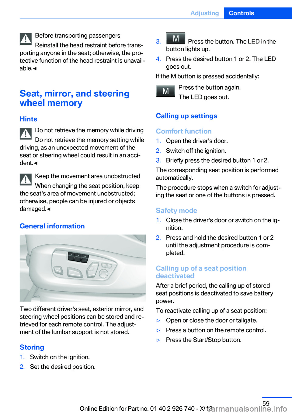
General information
Two different driver's seat, exterior mirror, and
steering wheel positions can be stored and re‐
trieved for each remote control. The adjust‐
ment of the lumbar support is not stored.
Storing
1.Switch on the ignition.2.Set the desired position.3. Press the button. The LED in the
button lights up.4.Press the desired button 1 or 2. The LED
goes out.
If the M button is pressed accidentally:
Press the button again.
The LED goes out.
Calling up settings
Comfort function
1.Open the driver's door.2.Switch off the ignition.3.Briefly press the desired button 1 or 2.
The corresponding seat position is performed
automatically.
The procedure stops when a switch for adjust‐
ing the seat or one of the buttons is pressed.
Safety mode
1.Close the driver's door or switch on the ig‐
nition.2.Press and hold the desired button 1 or 2
until the adjustment procedure is com‐
pleted.
Calling up of a seat position
deactivated
After a brief period, the calling up of stored
seat positions is deactivated to save battery
power.
To reactivate calling up of a seat position:
▷Open or close the door or tailgate.▷Press a button on the remote control.▷Press the Start/Stop button.Seite 59AdjustingControls59
Online Edition for Part no. 01 40 2 926 740 - X/13
Page 153 of 265
▷On uneven surfaces, such as speed
bumps.▷In large buildings with right angles and
smooth walls, e.g., in underground ga‐
rages.▷In heavy exhaust.▷Due to other ultrasound sources, e.g.,
sweeping machines, high pressure steam
cleaners or neon lights.
Malfunction
A Check Control message is displayed.
The range of the sensors is shown as a shaded
area on the Control Display.
PDC has failed. Have the system checked.
To ensure full operability:
▷Keep the sensors clean and free of ice.▷When using high-pressure washers, do not
spray the sensors for long periods and
maintain a distance of at least 12 in/30 cm.
Surround View
The concept Surround View comprises various camera as‐
sistance systems that help the driver when
parking, maneuvering, and at complex exits
and intersections.
▷Rearview camera, refer to page 153▷Top View, refer to page 156.▷Panorama Side View, refer to page 158.
Backup camera
The concept
The rearview camera provides assistance in
parking and maneuvering backwards. The area
behind the vehicle is shown on the Control
Display.
Hints
Check the traffic situation as well
Check the traffic situation around the ve‐
hicle with your own eyes. Otherwise, an acci‐
dent could result from road users or objects lo‐
cated outside the picture area of the backup
camera.◀
At a glance
Button in the vehicle
Rearview camera
Camera
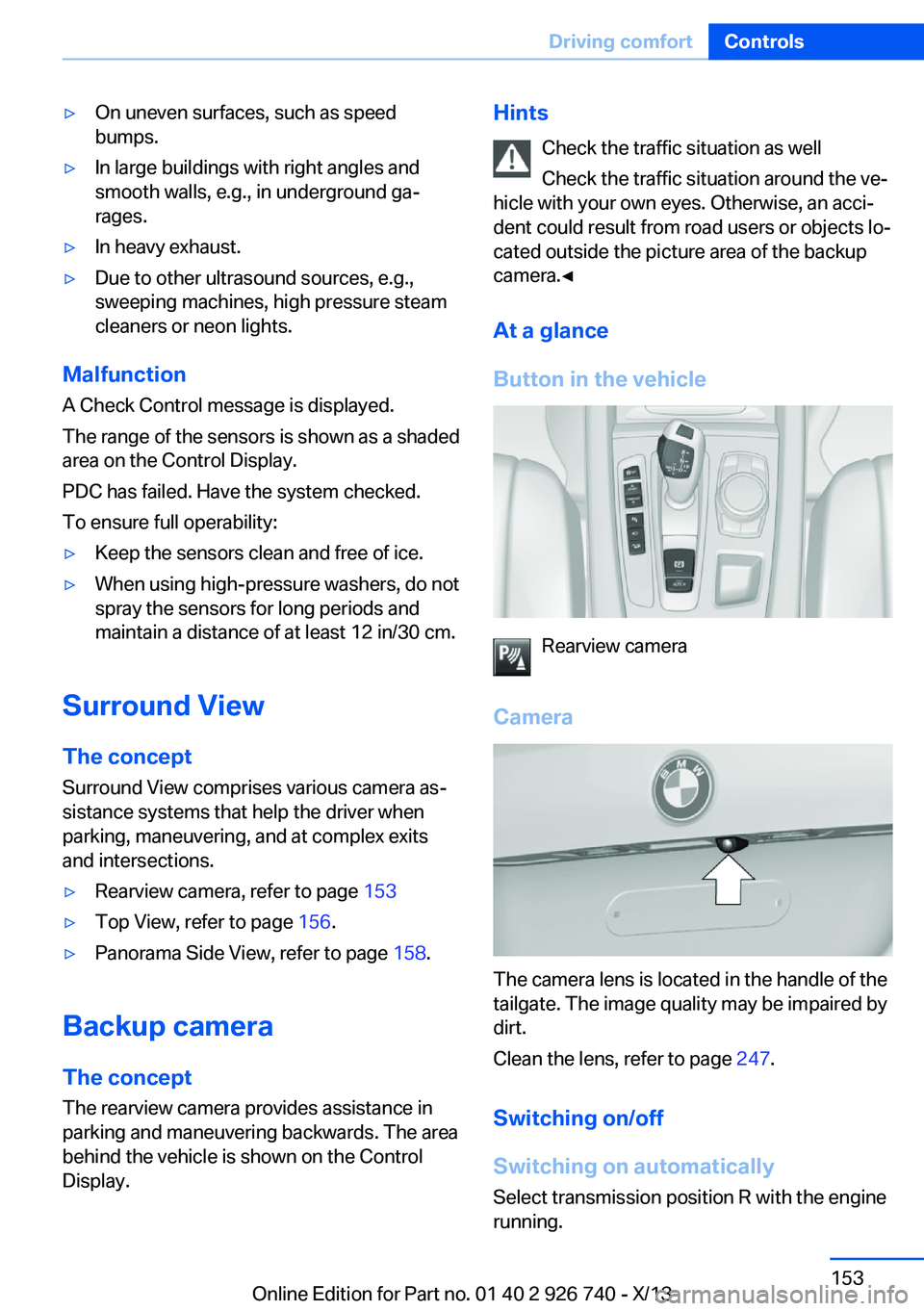
The camera lens is located in the handle of the
tailgate. The image quality may be impaired by
dirt.
Clean the lens, refer to page 247.
Switching on/off
Switching on automatically Select transmission position R with the engine
running.
Seite 153Driving comfortControls153
Online Edition for Part no. 01 40 2 926 740 - X/13
Page 154 of 265
The rearview camera image is displayed if the
system was switched on via the iDrive.
Automatic deactivation during forward
travel
The system switches off when a certain driving
distance or speed is exceeded.
Switch the system back on if necessary.
Switching on/off manually Press the button.▷On: the LED lights up.▷Off: the LED goes out.
The PDC is shown on the Control Display.
Switching on the rearview camera via
the iDrive
With PDC activated or Top View switched on:
"Rear view camera"
The rearview camera image is displayed. The
setting is stored for the remote control cur‐
rently in use.
Display on the Control Display
Functional requirement
▷The rearview camera is switched on.▷The tailgate is fully closed.
Activating the assistance functions
More than one assistance function can be ac‐
tive at the same time.
▷Parking aid lines
"Parking aid lines"
Pathway and turning circle lines are dis‐
played.
▷Obstacle marking
"Obstacle marking"
Spatially-shaped markings are displayed.
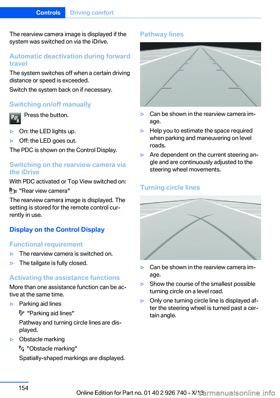
Pathway lines▷Can be shown in the rearview camera im‐
age.▷Help you to estimate the space required
when parking and maneuvering on level
roads.▷Are dependent on the current steering an‐
gle and are continuously adjusted to the
steering wheel movements.
Turning circle lines
▷Can be shown in the rearview camera im‐
age.▷Show the course of the smallest possible
turning circle on a level road.▷Only one turning circle line is displayed af‐
ter the steering wheel is turned past a cer‐
tain angle.Seite 154ControlsDriving comfort154
Online Edition for Part no. 01 40 2 926 740 - X/13
Page 156 of 265
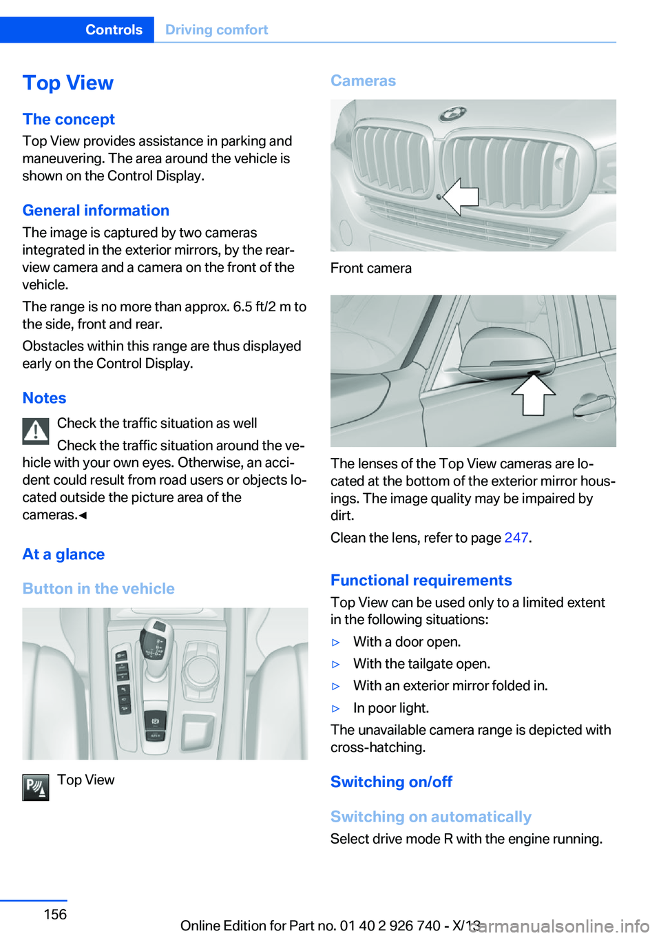
Top View
The concept Top View provides assistance in parking and
maneuvering. The area around the vehicle is
shown on the Control Display.
General information The image is captured by two cameras
integrated in the exterior mirrors, by the rear‐
view camera and a camera on the front of the
vehicle.
The range is no more than approx. 6.5 ft/2 m to
the side, front and rear.
Obstacles within this range are thus displayed
early on the Control Display.
Notes Check the traffic situation as well
Check the traffic situation around the ve‐
hicle with your own eyes. Otherwise, an acci‐
dent could result from road users or objects lo‐
cated outside the picture area of the
cameras.◀
At a glance
Button in the vehicle
Top View
Cameras
Front camera
The lenses of the Top View cameras are lo‐
cated at the bottom of the exterior mirror hous‐
ings. The image quality may be impaired by
dirt.
Clean the lens, refer to page 247.
Functional requirements
Top View can be used only to a limited extent
in the following situations:
▷With a door open.▷With the tailgate open.▷With an exterior mirror folded in.▷In poor light.
The unavailable camera range is depicted with
cross-hatching.
Switching on/off
Switching on automatically
Select drive mode R with the engine running.
Seite 156ControlsDriving comfort156
Online Edition for Part no. 01 40 2 926 740 - X/13
Page 160 of 265
Ultrasound sensors measure parking spaces
on both sides of the vehicle.
The parking assistant calculates the best pos‐
sible parking line and during the parking proce‐
dure takes control of steering, the acceleration
and braking and if necessary changes the drive
modes. Hold down the parking assistant but‐
ton for the duration of the parking operation. At
the end of the parking procedure, the P selec‐
tor lever position is engaged.
When parking, also take note of the visual and
acoustic information and instructions issued
by the PDC, the parking assistant and the rear‐
view camera and react accordingly.
A component of the parking assistant is the
PDC Park Distance Control, refer to page 150.
Hints Personal responsibility
Even an active system does not relieve
the driver from personal responsibility for the
driving process.
Because of technical system limits, the system
cannot independently react appropriately in all
traffic situations.
Continuously and attentively monitor the driv‐
ing process, the area surrounding the vehicle
and the traffic situation, and actively intervene
when required, otherwise, there is a risk of an
accident.◀
Changes to the parking space
Changes to the parking space after it was
measured are not taken into account by the
system.
Therefore, always be alert and ready to inter‐
vene; otherwise, there is the danger of an acci‐
dent occurring.◀
Transporting loads
Loads that extend beyond the perimeter
of the vehicle are not taken into account by the
system during the parking procedure.Therefore, always be alert and ready to inter‐
vene; otherwise, there is the danger of an acci‐
dent occurring.◀
Curbs
The parking assistant may steer the vehi‐
cle over or onto curbs.
Therefore, always be alert and ready to inter‐
vene; otherwise, the wheels, tires, or the vehi‐
cle may become damaged.◀
An engine that has been switched off by the
Auto Start Stop function is restarted automati‐
cally when the parking assistant is activated.
Requirements
For measuring parking spaces▷Maximum speed while driving forward ap‐
prox. 22 mph/35 km/h.▷Maximum distance to row of parked vehi‐
cles: 5 ft/1.5 m.
Suitable parking space
▷Gap between two objects with a minimum
length of approx. 5 ft/1.5 m.▷Minimum length of the gap: own vehicle's
length plus approx. 4 ft/1.2 m.▷Minimum depth: approx. 5 ft/1.5 m.
For parking procedure
▷Doors and tailgate closed.▷Parking brake released.Seite 160ControlsDriving comfort160
Online Edition for Part no. 01 40 2 926 740 - X/13
Page 163 of 265
Interrupting automaticallyThe system is interrupted automatically in the
following situations:▷When the button is released.▷If the driver grasps the steering wheel or if
he takes over steering.▷If a gear is selected that does not match
the instruction on the Control Display.▷During acceleration.▷When setting the parking brake.▷If a turn signal is activated in the opposite
direction to the desired side for parking.▷If the vehicle speed exceeds approx.
6 mph/10 km/h.▷On snow-covered or slippery road surfaces
if necessary.▷If doors are open.▷If the tailgate is open.▷When there are obstacles that are hard to
overcome, such as curbs.▷When there are obstacles that suddenly
arise.▷If a maximum number of parking attempts
or the time taken for parking is exceeded.
A Check Control message is displayed.
Continuing
An interrupted parking procedure can be con‐
tinued if necessary.
Follow the instructions on the Control Display
to do this.
System limits
No parking assistance The parking assistant does not offer assis‐
tance in the following situations:
▷In tight curves.Functional limitations
The system may not be fully functional in the
following situations:▷On bumpy road surfaces such as gravel
roads.▷On slippery ground.▷On steep uphill or downhill grades.▷When leaves or snow has collected in the
parking space.
Limits of ultrasonic measurement
The detection of objects can reach the physi‐
cal limits of ultrasonic measurement, e.g., in
the following circumstances:
▷For small children and animals.▷For persons with certain clothing, e.g.
coats.▷If there is an external disturbance of the ul‐
trasound, e.g. from passing vehicles or
loud machines.▷When sensors are soiled, iced over or dam‐
aged.▷Under certain weather conditions, e.g.,
high relative humidity, rain, snowfall or
strong wind.▷With tow bars and trailer hitches of other
vehicles.▷With thin or wedge-shaped objects.▷With moving objects.▷With elevated, protruding objects such as
ledges or cargo.▷With objects with corners and sharp edges.▷With objects with a fine surface structure,
such as fences.▷For objects with porous surfaces.
Low objects already displayed, e.g., curbs, can
move into the blind area of the sensors before
or after a continuous tone sounds.
The parking assistant may identify parking
spaces that are not suitable for parking.
Seite 163Driving comfortControls163
Online Edition for Part no. 01 40 2 926 740 - X/13
Page 190 of 265
Things to remember when drivingVehicle equipment
All standard, country-specific and optional
equipment that is offered in the model series is
described in this chapter. Therefore, equip‐
ment is also described that is not available in a
vehicle, e. g., because of the selected optional
equipment or country variant. This also applies
for safety-related functions and systems.
Breaking-in period General information Moving parts need to be broken in to adjust to
each other.
The following instructions will help achieve a
long vehicle life and good economy.
Engine and differential Always obey the official speed limit.
Up to 1,200 miles/2,000 km
Do not exceed the maximum engine and road
speed:▷For gasoline engine 4,500 rpm and
100 mph/160 km/h.▷For diesel engine 3,500 rpm and
93 mph/150 km/h.
Avoid full load or kickdown under all circum‐
stances.
From 1,200 miles/2,000 km The engine and vehicle speed can gradually be
increased.
Tires
Due to technical factors associated with their
manufacture, tires do not achieve their full
traction potential until after an initial breaking-
in period.
Drive conservatively for the first
200 miles/300 km.
Brake system
Brakes require an initial break-in period of ap‐
prox. 300 miles/500 km to achieve optimized
contact and wear patterns between brake
discs and brake pads. Drive moderately during
this break-in period.
Following part replacement
The same breaking in procedures should be
observed if any of the components mentioned
above have to be renewed in the course of the
vehicle's operating life.
General driving notes
Closing the tailgate Drive with the tailgate closed
Only drive with the tailgate closed; other‐
wise, in the event of an accident or braking and
evasive maneuvers, passengers and other road
users may be injured, and the vehicle may be
damaged. In addition, exhaust fumes may en‐
ter the passenger compartment.◀
If driving with the tailgate open cannot be
avoided:▷Close all windows and the glass sunroof.▷Greatly increase the blower speed.▷Drive moderately.
Hot exhaust system
Hot exhaust system
High temperatures are generated in the
exhaust system.
Seite 190Driving tipsThings to remember when driving190
Online Edition for Part no. 01 40 2 926 740 - X/13
Page 196 of 265
If available, the lashing eyes are located under
the cargo floor cover in the cargo area. They
can be inserted into the openings in the rails.
Securing cargo▷Smaller and lighter items: secure with re‐
taining straps or with a cargo net or draw
straps.▷Larger and heavy objects: secure with
cargo straps.
Cargo straps, cargo netting, retaining
straps or draw straps on the lashing eyes in
the cargo area.
Securing cargo
Always position and secure the cargo as
described above; otherwise, it can endanger
the car's occupants if sudden braking or
swerving becomes necessary.
Heavy or hard objects should not be carried
loose inside the car; otherwise, they could be
thrown around as a result of hard braking, sud‐
den swerves, etc., and endanger the occu‐
pants.◀
Roof-mounted luggage rack
Note Installation only possible with roof rack.
Roof racks are available as special accessories.
Securing
Follow the installation instructions of the roof
rack.
Loading Be sure that adequate clearance is maintained
for tilting and opening the glass sunroof.
Because roof racks raise the vehicle's center
of gravity when loaded, they have a major ef‐
fect on vehicle handling and steering re‐
sponse.
Therefore, note the following when loading
and driving:▷Do not exceed the approved roof/axle
loads and the approved gross vehicle
weight.▷Distribute the roof load uniformly.▷The roof load should not be too large in
area.▷Always place the heaviest pieces on the
bottom.▷Secure the roof luggage firmly, e.g., tie
with ratchet straps.▷Do not let objects project into the opening
path of the tailgate.▷Drive cautiously and avoid sudden acceler‐
ation and braking maneuvers. Take corners
gently.Seite 196Driving tipsLoading196
Online Edition for Part no. 01 40 2 926 740 - X/13
Page 254 of 265
Everything from A to Z
IndexA ABS, Antilock Brake Sys‐ tem 131
ACC, Active Cruise Control with Stop & Go 138
Acceleration Assistant, refer to Launch Control 80
Activated-charcoal filter 168
Active Blind Spot Detec‐ tion 126
Active Cruise Control with Stop & Go, ACC 138
Active Protection 128
Active roll stabilization 135
Active seat ventilation, front 53
Active Steering 134
Adaptive brake lights, refer to Brake force display 128
Adaptive Light Control 100
Additives, oil 225
Adjustments, seats/head re‐ straints 50
After washing vehicle 245
Airbags 104
Airbags, indicator/warning light 105
Air circulation, refer to Recir‐ culated-air mode 167
Air, dehumidifying, refer to Cooling function 167
Air distribution, manual 166
Air flow, automatic climate control 166
Air pressure, tires 211
Air vents, refer to Ventila‐ tion 168
Alarm system 45
Alarm, unintentional 46 All around the center con‐
sole 16
All around the headliner 17
All around the steering wheel 14
All-season tires, refer to Win‐ ter tires 219
All-wheel-drive 133
Alternating-code hand-held transmitter 176
Alternative oil types 226
Antifreeze, washer fluid 77
Antilock Brake System, ABS 131
Anti-slip control, refer to DSC 132
Approved axle load 250
Approved engine oils 225
Arrival time 94
Ashtray 177
Ashtray, front 177
Assistance, Roadside Assis‐ tance 240
Assistance when driving off 131
Assist system, refer to Intelli‐ gent Safety 112
Attentiveness assistant 128
AUTO H button, refer to Au‐ tomatic Hold 72
AUTO intensity 166
Automatic car wash 244
Automatic climate con‐ trol 165
Automatic Cruise Control with Stop & Go 138
Automatic Curb Monitor 60
Automatic deactivation, front passenger airbags 106
Automatic headlamp con‐ trol 100 Automatic Hold 72
Automatic locking 44
Automatic recirculated-air control 167
Automatic Soft Closing, doors 40
Automatic tailgate 40
Automatic transmission with Steptronic 78
AUTO program, automatic cli‐ mate control 166
AUTO program, intensity 166
Auto Start/Stop function 69
Average fuel consumption 94
Average speed 94
Axle loads, weights 250
B Backrest curvature, refer to Lumbar support 52
Backrest, width 53
Backup camera 153
Bad road trips 193
Band-aids, refer to First aid kit 240
Bar for tow-starting/ towing 243
Battery replacement, vehicle battery 237
Battery replacement, vehicle remote control 34
Battery, vehicle 237
Belts, safety belts 55
Beverage holder, cu‐ pholder 185
Blinds, sun protection 48
BMW Advanced Diesel 207
BMW Assist, see user's manual for Navigation, En‐Seite 254ReferenceEverything from A to Z254
Online Edition for Part no. 01 40 2 926 740 - X/13