clock BMW X5 XDRIVE 50I 2012 Owners Manual
[x] Cancel search | Manufacturer: BMW, Model Year: 2012, Model line: X5 XDRIVE 50I, Model: BMW X5 XDRIVE 50I 2012Pages: 317, PDF Size: 8.83 MB
Page 14 of 317
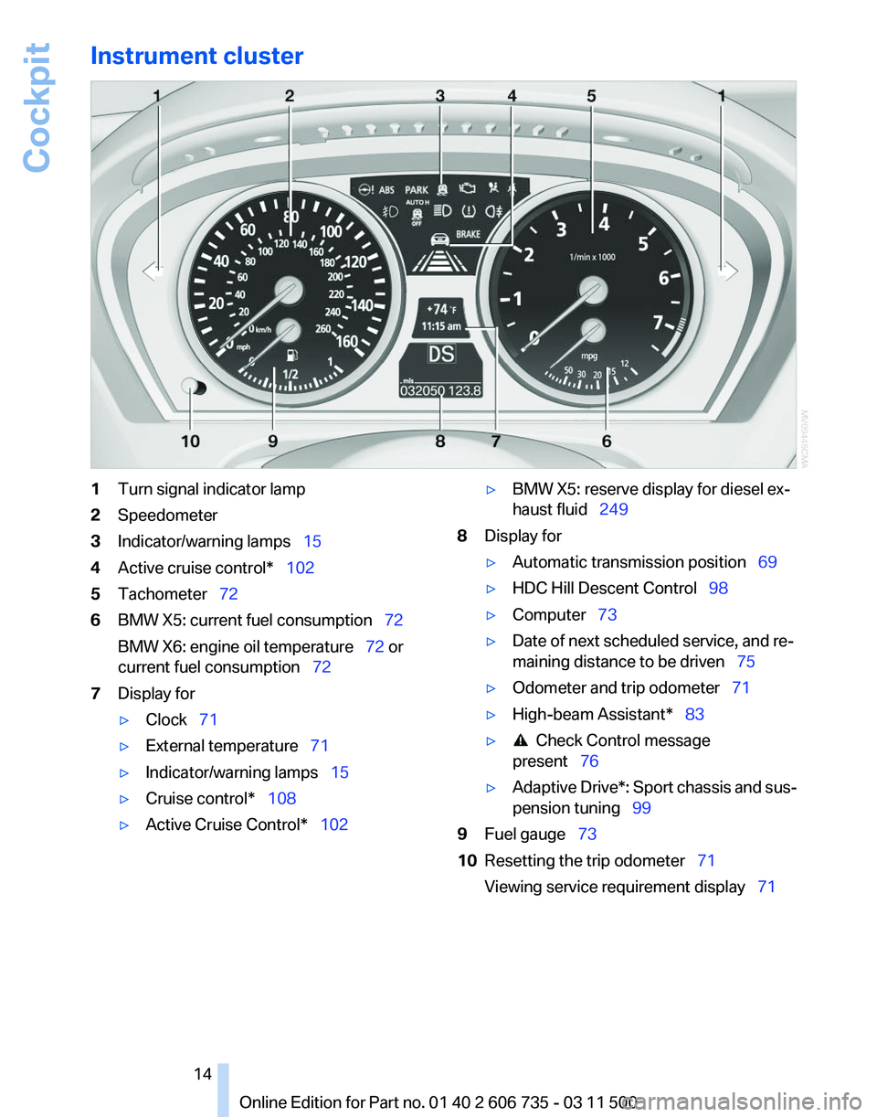
Instrument cluster
1
Turn signal indicator lamp
2 Speedometer
3 Indicator/warning lamps 15
4 Active cruise control* 102
5 Tachometer 72
6 BMW X5: current fuel consumption 72
BMW X6: engine oil temperature
72 or
current fuel consumption 72
7 Display for
▷Clock 71
▷ External temperature 71
▷ Indicator/warning lamps 15
▷ Cruise control* 108
▷ Active Cruise Control* 102 ▷
BMW X5: reserve display for diesel ex‐
haust fluid 249
8 Display for
▷Automatic transmission position 69
▷ HDC Hill Descent Control 98
▷ Computer 73
▷ Date of next scheduled service, and re‐
maining distance to be driven
75
▷ Odometer and trip odometer 71
▷ High-beam Assistant* 83
▷ Check Control message
present 76
▷ Adaptive Drive*:
Sport chassis and sus‐
pension tuning 99
9 Fuel gauge 73
10 Resetting the trip odometer 71
Viewing service requirement display 71
Seite 14
14 Online Edition for Part no. 01 40 2 606 735 - 03 11 500
Cockpit
Page 21 of 317
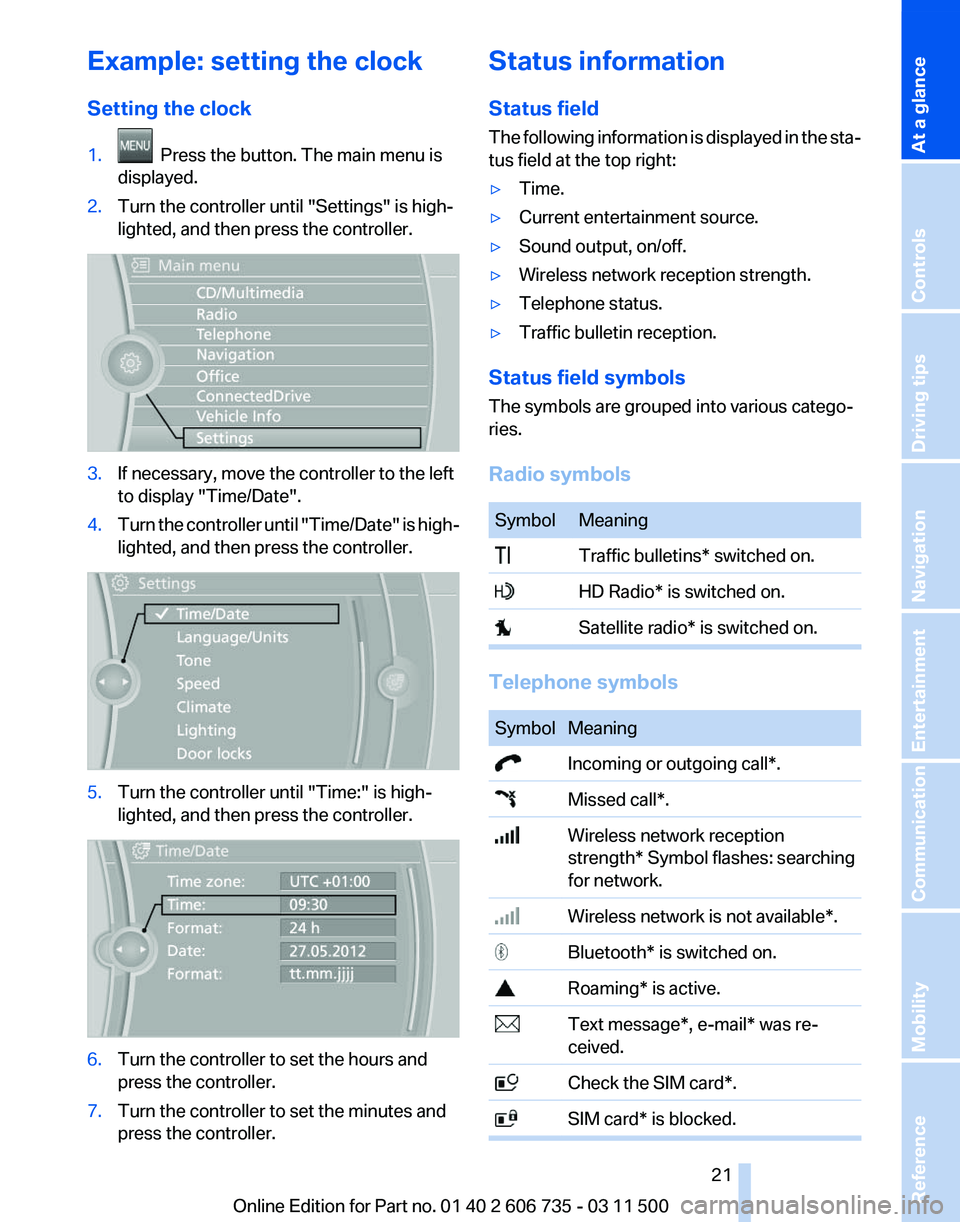
Example: setting the clock
Setting the clock
1.
Press the button. The main menu is
displayed.
2. Turn the controller until "Settings" is high‐
lighted, and then press the controller. 3.
If necessary, move the controller to the left
to display "Time/Date"
.
4. Turn the controller until "Time/Date"
is high‐
lighted, and then press the controller. 5.
Turn the controller until "Time:" is high‐
lighted, and then press the controller. 6.
Turn the controller to set the hours and
press the controller.
7. Turn the controller to set the minutes and
press the controller. Status information
Status field
The
following information is displayed in the sta‐
tus field at the top right:
▷ Time.
▷ Current entertainment source.
▷ Sound output, on/off.
▷ Wireless network reception strength.
▷ Telephone status.
▷ Traffic bulletin reception.
Status field symbols
The symbols are grouped into various catego‐
ries.
Radio symbols Symbol Meaning
Traffic bulletins* switched on.
HD Radio* is switched on.
Satellite radio* is switched on.
Telephone symbols
Symbol Meaning
Incoming or outgoing call*.
Missed call*.
Wireless network reception
strength*
Symbol flashes: searching
for network. Wireless network is not available*.
Bluetooth* is switched on.
Roaming* is active.
Text message*, e-mail* was re‐
ceived. Check the SIM card*.
SIM card* is blocked. Seite 21
21Online Edition for Part no. 01 40 2 606 735 - 03 11 500
Reference Mobility Communication Entertainment Navigation Driving tips Controls
At a glance
Page 29 of 317
The individual settings are stored for a maximum
of
four remote controls. They are stored for two
remote controls if Comfort Access* is in use.
Personal Profile settings
The following functions and settings can be
stored in a profile.
More information on the settings can be found
under:
▷ Assigning the programmable memory but‐
tons, refer to page 22.
▷ Response of the central locking system
when the car is being unlocked, refer to
page 30.
▷ Automatic locking of the vehicle, refer to
page 33.
▷ Driver's seat, exterior mirror and steering
wheel positions*, refer to page 53.
▷ Settings for the display on the Control Dis‐
play and in the instrument cluster:
▷12h/24h clock format, refer to
page 79.
▷ Date format, refer to page 79.
▷ Brightness of the Control Display, refer
to page 80.
▷ Language on the Control Display, refer
to page 80.
▷ Units of measure for fuel consumption,
distance covered/remaining distances,
and temperature, refer to page 80.
▷ Show visual warning for the Park Distance
Control PDC*, refer to page 111.
▷ Show visual warning for Top View*, refer to
page 114.
▷ Show Side View*, refer to page 116.
▷ Backup camera*:
▷Function selection, refer to page 113.
▷ Type of display, refer to page 114.
▷ Lane departure warning*: last setting, on/
off, refer to page 93.
▷ Head-up Display*: selection, brightness and
position of the display, refer to page 117.▷
Adaptive Drive*: selected chassis and sus‐
pension tuning, refer to page 99.
▷ Light settings:
▷Triple turn signal activation, refer to
page 66.
▷ Welcome lamps, refer to page 81.
▷ Headlamp courtesy delay feature, refer
to page 81.
▷ Daytime running lights, refer to
page 82.
▷ High-beam Assistant*, refer to
page 83.
▷ Automatic climate control with 2-zone con‐
trol: settings, refer to page 120.
▷ Navigation:
▷Voice activation, refer to page 163.
▷ Route criteria, refer to page 161.
▷ Map view settings, refer to page 164.
▷ Entertainment:
▷Tone control, refer to page 172.
▷ Radio, stored stations, refer to
page 180.
▷ CD/multimedia, audio source listened to
last, refer to page 181.
▷ Telephone: volume, refer to page 220.
Central locking system
The concept
The central locking system becomes active
when the driver's door is closed.
The system simultaneously engages and re‐
leases the locks on the following:
▷ Doors.
▷ Tailgate.
▷ Fuel filler flap.
Operating from the outside
▷ Via the remote control.
▷ Via the door lock*.
Seite 29
29Online Edition for Part no. 01 40 2 606 735 - 03 11 500
Reference Mobility Communication Entertainment Navigation Driving tips
Controls At a glance
Page 71 of 317
Displays
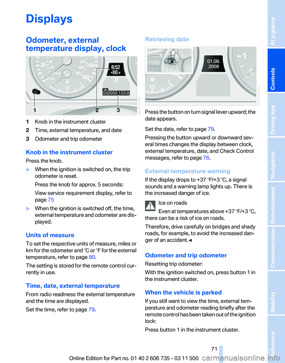
Odometer, external
temperature display, clock
1
Knob in the instrument cluster
2 Time, external temperature, and date
3 Odometer and trip odometer
Knob in the instrument cluster
Press the knob.
▷ When the ignition is switched on, the trip
odometer is reset.
Press the knob for approx. 5 seconds:
View service requirement display, refer to
page 75
▷ When the ignition is switched off, the time,
external
temperature and odometer are dis‐
played.
Units of measure
To
set the respective units of measure, miles or
km for the odometer and ℃ or ℉ for the external
temperature, refer to page 80.
The setting is stored for the remote control cur‐
rently in use.
Time, date, external temperature
From radio readiness the external temperature
and the time are displayed.
Set the time, refer to page 79.Retrieving date
Press the button on turn signal lever upward; the
date appears.
Set the date, refer to page
79.
Pressing the button upward or downward sev‐
eral times changes the display between clock,
external temperature, date, and Check Control
messages, refer to page 76.
External temperature warning
If the display drops to +37 ℉/+3 ℃, a signal
sounds and a warning lamp lights up. There is
the increased danger of ice. Ice on roads
Even
at temperatures above +37 ℉/+3 ℃,
there can be a risk of ice on roads.
Therefore, drive carefully on bridges and shady
roads, for example, to avoid the increased dan‐
ger of an accident.◀
Odometer and trip odometer
Resetting trip odometer:
With the ignition switched on, press button 1 in
the instrument cluster.
When the vehicle is parked
If you still want to view the time, external tem‐
perature and odometer reading briefly after the
remote control has been taken out of the ignition
lock:
Press button 1 in the instrument cluster. Seite 71
71Online Edition for Part no. 01 40 2 606 735 - 03 11 500
Reference Mobility Communication Entertainment Navigation Driving tips
Controls At a glance
Page 86 of 317
Safety
Airbags
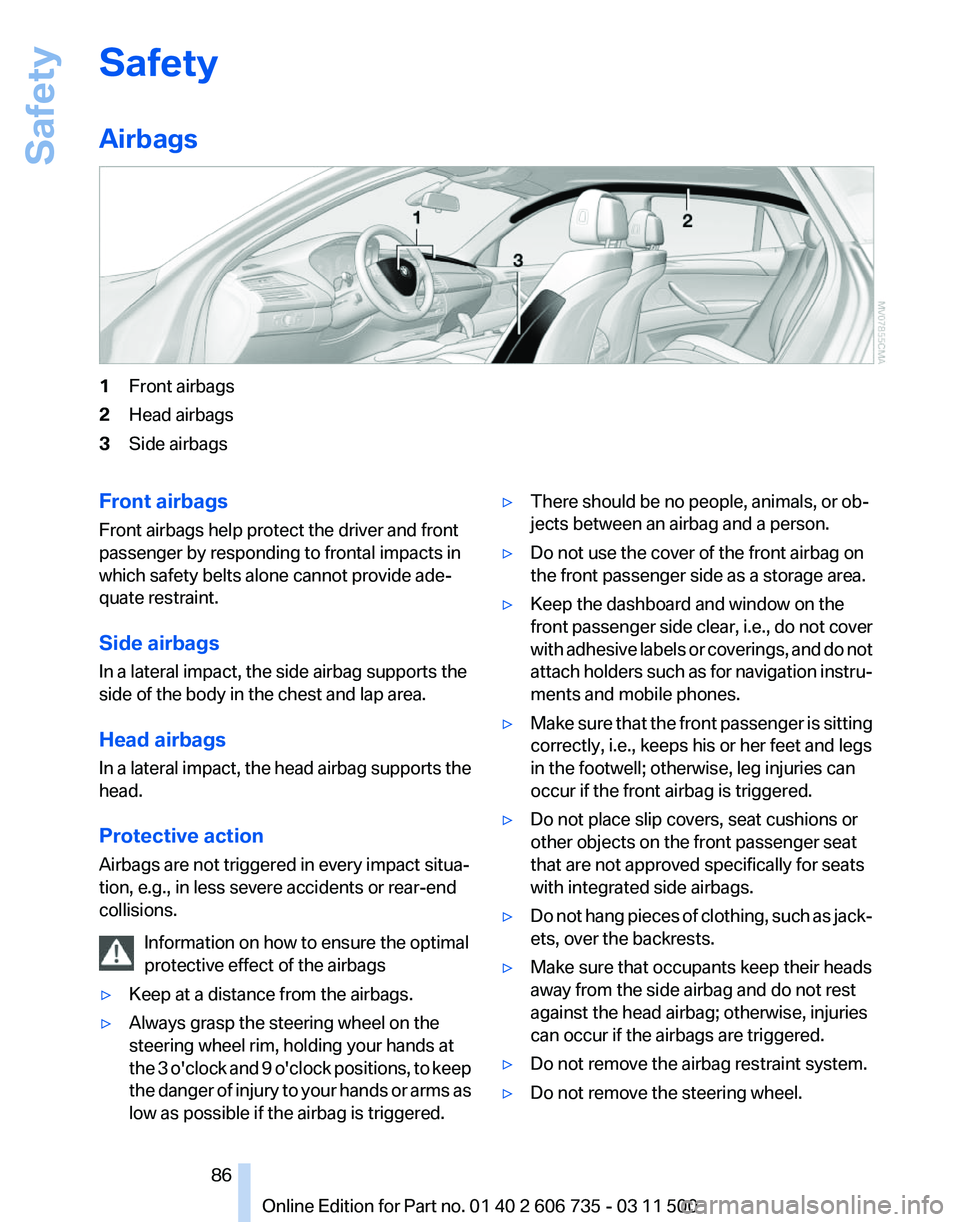
1
Front airbags
2 Head airbags
3 Side airbags
Front airbags
Front airbags help protect the driver and front
passenger by responding to frontal impacts in
which safety belts alone cannot provide ade‐
quate restraint.
Side airbags
In a lateral impact, the side airbag supports the
side of the body in the chest and lap area.
Head airbags
In
a lateral impact, the head airbag supports the
head.
Protective action
Airbags are not triggered in every impact situa‐
tion, e.g., in less severe accidents or rear-end
collisions.
Information on how to ensure the optimal
protective effect of the airbags
▷ Keep at a distance from the airbags.
▷ Always grasp the steering wheel on the
steering wheel rim, holding your hands at
the
3 o'clock and 9 o'clock positions, to keep
the danger of injury to your hands or arms as
low as possible if the airbag is triggered. ▷
There should be no people, animals, or ob‐
jects between an airbag and a person.
▷ Do not use the cover of the front airbag on
the front passenger side as a storage area.
▷ Keep the dashboard and window on the
front
passenger side clear, i.e., do not cover
with adhesive labels or coverings, and do not
attach holders such as for navigation instru‐
ments and mobile phones.
▷ Make sure that the front passenger is sitting
correctly, i.e., keeps his or her feet and legs
in the footwell; otherwise, leg injuries can
occur if the front airbag is triggered.
▷ Do not place slip covers, seat cushions or
other objects on the front passenger seat
that are not approved specifically for seats
with integrated side airbags.
▷ Do not hang pieces of clothing, such as jack‐
ets, over the backrests.
▷ Make sure that occupants keep their heads
away from the side airbag and do not rest
against the head airbag; otherwise, injuries
can occur if the airbags are triggered.
▷ Do not remove the airbag restraint system.
▷ Do not remove the steering wheel.
Seite 86
86 Online Edition for Part no. 01 40 2 606 735 - 03 11 500
Safety
Page 246 of 317
Refueling
Notes
Switch off the engine before refueling
Always switch off the engine before refu‐
eling; otherwise, fuel cannot be added to the
tank and a message will be displayed.
◀
Observe when handling fuel
▷ Take all precautionary measures and
observe all applicable regulations
when handling fuel.
▷ Do not carry any spare fuel containers in
your vehicle. They can develop a leak and
cause an explosion or cause a fire in the
event of an accident.◀
Fuel cap
Opening
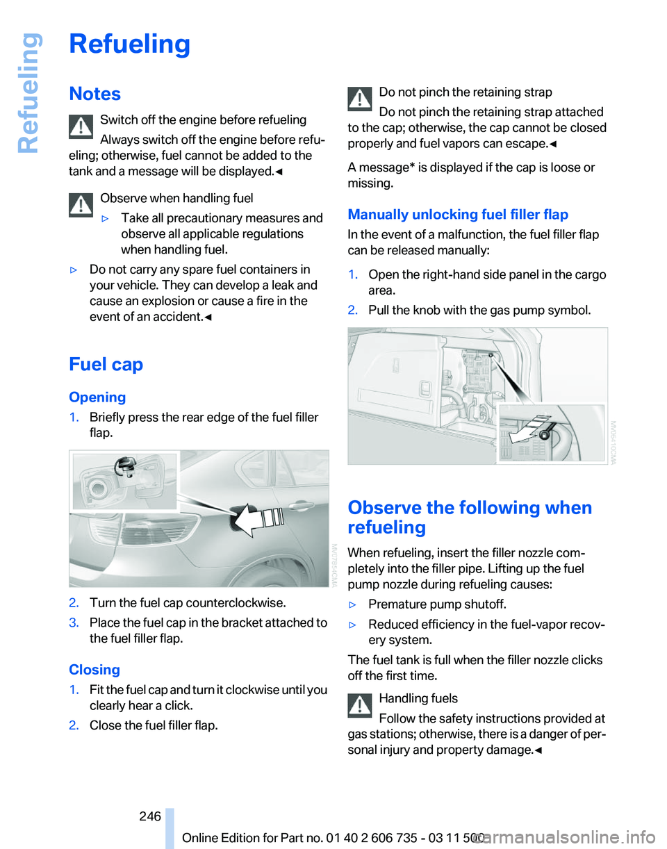
1. Briefly press the rear edge of the fuel filler
flap. 2.
Turn the fuel cap counterclockwise.
3. Place the fuel cap in the bracket attached to
the fuel filler flap.
Closing
1. Fit the fuel cap and turn it clockwise until you
clearly hear a click.
2. Close the fuel filler flap. Do not pinch the retaining strap
Do not pinch the retaining strap attached
to the cap; otherwise, the cap cannot be closed
properly and fuel vapors can escape.◀
A message* is displayed if the cap is loose or
missing.
Manually unlocking fuel filler flap
In the event of a malfunction, the fuel filler flap
can be released manually:
1. Open the right-hand side panel in the cargo
area.
2. Pull the knob with the gas pump symbol. Observe the following when
refueling
When refueling, insert the filler nozzle com‐
pletely into the filler pipe. Lifting up the fuel
pump nozzle during refueling causes:
▷
Premature pump shutoff.
▷ Reduced efficiency in the fuel-vapor recov‐
ery system.
The fuel tank is full when the filler nozzle clicks
off the first time.
Handling fuels
Follow the safety instructions provided at
gas
stations; otherwise, there is a danger of per‐
sonal injury and property damage.◀ Seite 246
246 Online Edition for Part no. 01 40 2 606 735 - 03 11 500
Refueling
Page 267 of 317
Coolant
General information
Danger of burns from hot engine
Do not open the cooling system while the
engine is hot; otherwise, escaping coolant may
cause burns.◀
Suitable additives
Only
use suitable additives; otherwise, en‐
gine damage may occur. The additives are
harmful to your health.◀
Coolant consists of water and additives.
Not all commercially available additives are suit‐
able for your vehicle. Ask your service center for
suitable additives.
Checking the coolant level
1. Do not open the hood until the engine has
cooled down.
2. Turn the expansion tank cap counterclock‐
wise
slightly to allow any accumulated pres‐
sure to escape; then continue turning to
open.
3. The coolant level is correct if it is between
the maximum and minimum marks in the
filler neck, refer also to the diagram next to
the filler neck.
4. If the coolant is low, slowly add coolant up to
the specified level; do not overfill.
5. Turn the cap until there is an audible click.
6. Have the cause of the coolant loss elimi‐
nated as soon as possible. Disposal
Comply
with the appropriate environmen‐
tal protection regulations when disposing
of coolant additives. Seite 267
267Online Edition for Part no. 01 40 2 606 735 - 03 11 500
Reference
Mobility Communication Entertainment Navigation Driving tips Controls At a glance
Page 281 of 317
▷
If the LED is flashing but the BMW Assist
Response Center cannot be heard on the
hands-free system, the hands-free system
may be malfunctioning. However, the BMW
Assist
Response Center may still be able to
hear you.
Initiating an Emergency Request
automatically
Under certain conditions, an Emergency Re‐
quest
is automatically initiated immediately after
a severe accident. Automatic Collision Notifica‐
tion is not affected by pressing the SOS button.
Roadside Assistance*
Service availability
Roadside Assistance can be reached around the
clock in many countries. You can obtain assis‐
tance there in the event of a vehicle breakdown.
Roadside Assistance
The Roadside Assistance, refer to page 238
phone number can be viewed on the iDrive or a
connection to Roadside Assistance* can be es‐
tablished directly.
Warning triangle*
The warning triangle is located in the cargo area.
First aid kit*
The first aid kit is located in a storage compart‐
ment on the right side in the cargo area.
Some of the articles contained in the first aid
pouch have a limited service life.
Check the expiration dates of the contents reg‐
ularly and replace any items promptly. Jump-starting
Notes
If the battery is discharged, an engine can be
started using the battery of another vehicle and
two jumper cables*. Only use jumper cables
with fully insulated clamp handles.
To prevent personal injury or damage to both
vehicles, adhere strictly to the following proce‐
dure.
Do not touch live parts
To avoid the risk of potentially fatal injury,
always avoid all contact with electrical compo‐
nents while the engine is running.◀
Preparation
1. Check whether the battery of the other ve‐
hicle has a voltage of 12 volts and approxi‐
mately
the same capacitance in Ah. This in‐
formation can be found on the battery.
2. Switch off the engine of the assisting vehi‐
cle.
3. Switch off any electronic systems/power
consumers in both vehicles.
Bodywork contact between vehicles
There must not be any contact between
the bodies of the two vehicles, otherwise there
is a danger of shorting.◀
Starting aid terminals
Connecting order
Connect the jumper cables in the correct
order; otherwise, there is the danger of injury
from sparking.◀ Seite 281
281Online Edition for Part no. 01 40 2 606 735 - 03 11 500
Reference
Mobility Communication Entertainment Navigation Driving tips Controls At a glance
Page 304 of 317
Camera, refer to Backup cam‐
era 112
Camera, Side View 117
Camera, Top View 116
Can holder, refer to Cu‐ pholder 135
Car battery, refer to Vehicle battery 278
Car care products 286
Care 285
Care, displays 287
Care, vehicle 286
Cargo 144
Cargo area
– Comfort Access 38
Cargo area, capacities 292
Cargo area, enlarging 133
Cargo area lamp, refer to Inte‐ rior lamps 84
Cargo area lid, refer to Tail‐ gate 33, 36
Cargo area, opening/closing, refer to Lower tailgate 36
Cargo area, opening/closing, refer to Tailgate 33, 36
Cargo area, opening from the inside 34
Cargo area, opening from the outside 34
Cargo area, refer to Cargo area 132
Cargo cover, refer to Luggage compartment roller
cover 132
Cargo, securing with ski bag, refer to Securing cargo 139
Cargo straps, securing cargo 146
Car key, refer to Integrated key/remote control 28
Carpet, care 287
Car phone, installation loca‐ tion, refer to Center arm‐
rest 134
Car phone, refer to Tele‐ phone 216
Car vacuum cleaner, connect‐ ing,
refer to Connecting elec‐
trical devices 131 Car wash 285
Catalytic converter, refer to
Hot exhaust system 142
CBC, refer to Cornering Brake Control 96
CBS Condition Based Serv‐ ice 268
CD/DVD 181
CD/DVD changer 185
CD/DVD in rear 201
CD/DVD notes 187
CD, refer to Playing audio tracks,
rear DVD system 206
CDs, storing 188
Cell phone 216
Cell phone, installation loca‐ tion, refer to Center arm‐
rest 134
Center armrest, front 134
Center armrest, rear 135
Center brake lamp 273, 275
Center console, refer to Around the center con‐
sole 16
Central locking
– Comfort Access 37
– From the inside 33
– Setting the unlocking char‐ acteristics 30
Central locking system
– From the outside 29
– Principle 29
Central screen, refer to Control
Display 19
Changes, technical, refer to Safety 6
Changing wheels/tires 260
Chassis number, refer to En‐ gine compartment 263
Check Control 76
Children, transporting 56
Child restraint fixing system LATCH 57
Child restraint fixing sys‐ tems 56
Child restraint fixing systems, mounting 56
Child safety locks 60
Child seat, mounting 56 Child seats, refer to Transport‐
ing children safely 56
Chrome parts, care 286
Cigarette lighter, connecting electrical devices 131
Cigarette lighter, refer to Lighter 130
Cigarette lighter socket 131
Circulation of air, refer to Re‐ circulated air mode 122
Cleaning, displays 287
Cleaning your BMW, refer to Care 285
Clock 71
Clock, 12h/24h mode 79
Closing
– From the inside 33
– From the outside 30
Clothes hooks 135
Cockpit 12
Cold
start, refer to Starting the
engine 62
Combination instrument, refer to Instrument cluster 14
Combination switch, refer to Turn signal/high beams/
headlamp flasher 66
Combination switch, refer to Washer/wiper system 67
Comfort Access
– Battery replacement 39
Comfort area, refer to Around
the center console 16
Compact
wheel, inflation pres‐
sure 252, 253
Compartment for remote con‐ trol, refer to Ignition lock 61
Compartments, refer to Stor‐ age compartments 134, 135
Compass, digital 129
Computer 73
Computer, displaying informa‐ tion 73
Computer, displays on the Control Display 74
Concierge service 238
Condensation on windows, re‐ moving 121
Seite 304
304 Online Edition for Part no. 01 40 2 606 735 - 03 11 500
Everything from A to Z
Page 305 of 317
Condensation under the vehi‐
cle 144
Condition Based Service CBS 268
Confirmation signals for lock‐ ing/unlocking the vehicle 31
ConnectedDrive 237
Connecting,
mobile phone, re‐
fer to Pairing the mobile
phone 216
Consumption, refer to Aver‐ age fuel consumption 74
Contacts 227, 235
Control Display 19
Control Display, care 287
Control Display, setting the brightness 80
Controller, refer to Con‐ trols 18
Controls and displays 12
Controls, rear DVD sys‐ tem 200
Control systems, driving sta‐ bility 96
Convenient operation
– Glass sunroof 30, 32
– Window 30
Coolant 267
Coolant, checking the
level 267
Coolant temperature 72
Cooling
function, switching on
and off 122
Cooling, maximum 122
Cooling system, refer to Cool‐ ant 267
Cornering Brake Control CBC 96
Corrosion on brake discs 144
Courtesy lamps, refer to Inte‐ rior lamps 84
Cradle for telephone or mobile phone, refer to Snap-in
adapter 225
Cruise control 108
Cruise control
– Malfunction 110
Cruise control, active 102
Cupholder 135 Curb weight, refer to
Weights 292
Current fuel consumption 72
Current location, storing 155
Curve lights, refer to Adaptive light control 82
Cylinders, number of, refer to Engine data 290
D
Dashboard
lighting, refer to In‐
strument lighting 84
Dashboard, refer to Cock‐ pit 12
Data memory 269
Data, technical 290
Date 71
Date, display format 79
Date, retrieving 71
Date, setting 79
Daytime running lights 82
Defroster, rear window 121
Defrosting windows 121
Defrost setting, refer to De‐ frosting windows 121
Destination entry via the ad‐ dress book 154
Destination guidance 161
Destination guidance with in‐ termediate destinations 159
Destination input, naviga‐ tion 153
Diesel exhaust fluid, at low temperatures 250
Diesel exhaust fluid, at mini‐ mum 249
Diesel exhaust fluid, having re‐ filled 250
Diesel exhaust fluid, refilling yourself 250
Diesel particulate filter 143
Digital clock 71
Digital compass 129
Digital radio 175
Dimming mirrors 55
Directional indicators, refer to Turn signals 66 Displacement, refer to Engine
data 290
Display in front wind‐ shield 117
Display
lighting, refer to Instru‐
ment lighting 84
Displays and controls 12
Displays, care 287
Displays, cleaning 287
Displays, refer to Instrument cluster 14
Disposal, coolant 267
Disposal, vehicle battery 278
Distance control, refer to Ac‐ tive Cruise Control 102
Distance, selecting, with Ac‐ tive Cruise Control 104
Distance warning, refer to Park Distance Control PDC 110
Divided screen view, split screen 22
Door key, refer to Remote con‐ trol with integrated key 28
Door lock 32
Doors, manual operation 32
Doors, unlocking and locking
– Confirmation signals 31
– From the inside 33
– From the outside 30
DOT Quality Grades 258
Downhill control 98
Draft-free ventilation 123
Drive-off assistant 100
Driver's seat, calibrating 51
Driving away on inclines, refer to Drive-off assistant 100
Driving
notes, breaking in 142
Driving notes, general 142
Driving on poor roads 147
Driving stability control sys‐ tems 96
Driving through water 143
Driving tips, refer to Driving notes 142
Dry air, refer to Cooling func‐ tion 122
DSC Dynamic Stability Con‐ trol 96
Seite 305
305Online Edition for Part no. 01 40 2 606 735 - 03 11 500
Reference Mobility Communication Entertainment Navigation Driving tips Controls At a glance