BMW X5 XDRIVE35D 2012 Owners Manual
Manufacturer: BMW, Model Year: 2012, Model line: X5 XDRIVE35D, Model: BMW X5 XDRIVE35D 2012Pages: 317, PDF Size: 8.83 MB
Page 271 of 317
Do not touch the bulbs
Do not touch the glass of new bulbs with
your bare hands, as even minute amounts of
contamination will burn into the bulb's surface
and reduce its service life.
Use
a clean tissue, cloth or something similar, or
hold the bulb by its base.◀
Light-emitting diodes LED
Light-emitting diodes installed behind translu‐
cent lenses serve as the light source for many of
the controls, displays and other equipment in
your vehicle.
These light-emitting diodes, which operate us‐
ing a concept similar to that applied in conven‐
tional lasers, are officially designated as Class 1
light-emitting diodes.
Do not remove the covers
Do not remove the covers, and never stare
into the unfiltered light for several hours; other‐
wise, irritation of the retina could result.◀
Headlamp glass
Condensation can form on the inside of the ex‐
ternal lamps in cool or humid weather. When the
light is switched on, the condensation evapo‐
rates after a short time. The headlamp glasses
do not need to be changed.
If there is a large amount of moisture, e.g., water
droplets form in the lamp, have the lamp
checked by your service center.
BMW X5: bulb replacement
Xenon headlamps
Because of the long life of these bulbs, the like‐
lihood of failure is very low. Switching the lamps
on and off frequently shortens their life.
If a bulb fails, switch on the front fog lamps* and
continue the trip with great care. Comply with
local regulations. Do not perform work/bulb replacement on
xenon headlamps
Have
any work on the xenon lighting system, in‐
cluding bulb replacement, performed only by a
service center.
Due to the high voltage present in the system,
there is the danger of fatal injuries if work is car‐
ried out improperly.◀
Parking lamps, roadside parking lamps,
daytime running lights*
These lamps are made using LED technology.
Contact your service center in the event of a
malfunction.
Turn signals, front
24-watt bulb, PY24W
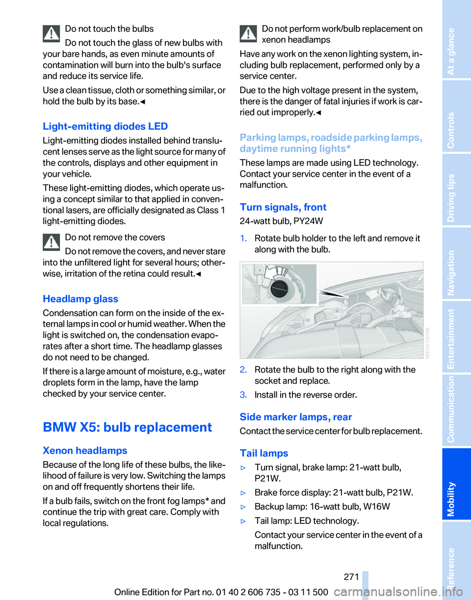
1. Rotate bulb holder to the left and remove it
along with the bulb. 2.
Rotate the bulb to the right along with the
socket and replace.
3. Install in the reverse order.
Side marker lamps, rear
Contact
the service center for bulb replacement.
Tail lamps
▷ Turn signal, brake lamp: 21-watt bulb,
P21W.
▷ Brake force display: 21-watt bulb, P21W.
▷ Backup lamp: 16-watt bulb, W16W
▷ Tail lamp: LED technology.
Contact
your service center in the event of a
malfunction. Seite 271
271Online Edition for Part no. 01 40 2 606 735 - 03 11 500
Reference
Mobility Communication Entertainment Navigation Driving tips Controls At a glance
Page 272 of 317
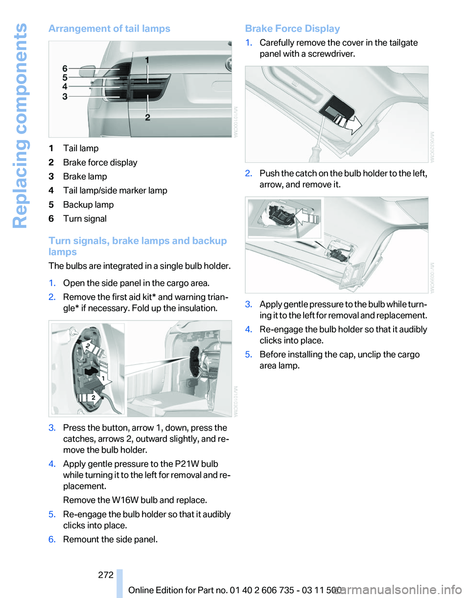
Arrangement of tail lamps
1
Tail lamp
2 Brake force display
3 Brake lamp
4 Tail lamp/side marker lamp
5 Backup lamp
6 Turn signal
Turn signals, brake lamps and backup
lamps
The
bulbs are integrated in a single bulb holder.
1. Open the side panel in the cargo area.
2. Remove the first aid kit* and warning trian‐
gle* if necessary. Fold up the insulation. 3.
Press the button, arrow 1, down, press the
catches, arrows 2, outward slightly, and re‐
move the bulb holder.
4. Apply gentle pressure to the P21W bulb
while
turning it to the left for removal and re‐
placement.
Remove the W16W bulb and replace.
5. Re-engage the bulb holder so that it audibly
clicks into place.
6. Remount the side panel. Brake Force Display
1.
Carefully remove the cover in the tailgate
panel with a screwdriver. 2.
Push the catch on the bulb holder to the left,
arrow, and remove it. 3.
Apply gentle pressure to the bulb while turn‐
ing
it to the left for removal and replacement.
4. Re-engage the bulb holder so that it audibly
clicks into place.
5. Before installing the cap, unclip the cargo
area lamp.
Seite 272
272 Online Edition for Part no. 01 40 2 606 735 - 03 11 500
Replacing components
Page 273 of 317
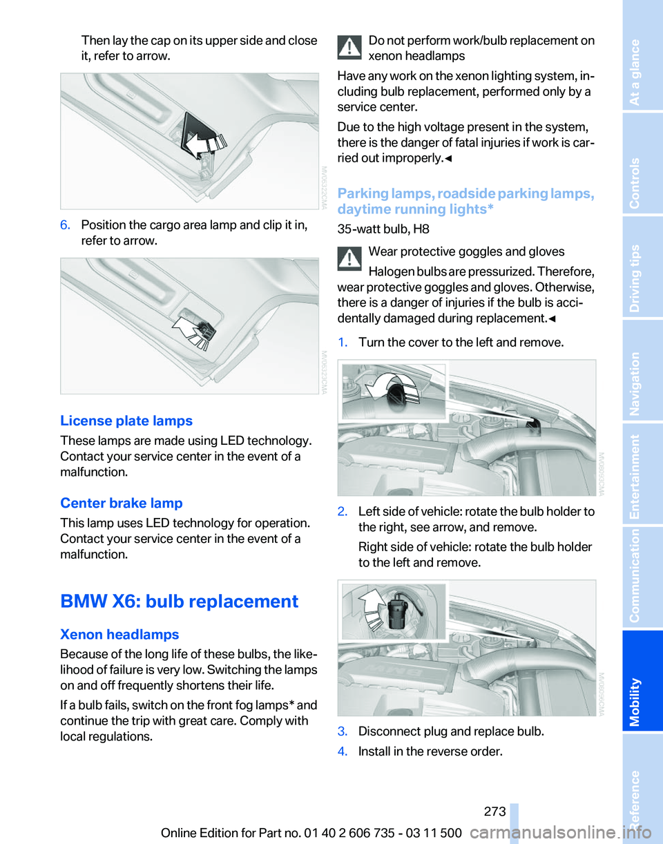
Then lay the cap on its upper side and close
it, refer to arrow.
6.
Position the cargo area lamp and clip it in,
refer to arrow. License plate lamps
These lamps are made using LED technology.
Contact your service center in the event of a
malfunction.
Center brake lamp
This lamp uses LED technology for operation.
Contact your service center in the event of a
malfunction.
BMW X6: bulb replacement
Xenon headlamps
Because
of the long life of these bulbs, the like‐
lihood of failure is very low. Switching the lamps
on and off frequently shortens their life.
If a bulb fails, switch on the front fog lamps* and
continue the trip with great care. Comply with
local regulations. Do not perform work/bulb replacement on
xenon headlamps
Have
any work on the xenon lighting system, in‐
cluding bulb replacement, performed only by a
service center.
Due to the high voltage present in the system,
there is the danger of fatal injuries if work is car‐
ried out improperly.◀
Parking lamps, roadside parking lamps,
daytime running lights*
35-watt bulb, H8
Wear protective goggles and gloves
Halogen bulbs are pressurized. Therefore,
wear protective goggles and gloves. Otherwise,
there is a danger of injuries if the bulb is acci‐
dentally damaged during replacement.◀
1. Turn the cover to the left and remove. 2.
Left side of vehicle: rotate the bulb holder to
the right, see arrow, and remove.
Right side of vehicle: rotate the bulb holder
to the left and remove. 3.
Disconnect plug and replace bulb.
4. Install in the reverse order. Seite 273
273Online Edition for Part no. 01 40 2 606 735 - 03 11 500
Reference
Mobility Communication Entertainment Navigation Driving tips Controls At a glance
Page 274 of 317
Side marker lamps
5-watt bulb, WY5W XLL
1.
Rotate the bulb holder to the left and re‐
move. 2.
Pull the bulb out of the bulb holder and re‐
place.
3. Install in the reverse order.
Turn signals, front
24-watt bulb, PY24W
1. Rotate bulb holder to the left and remove it
along with the bulb. 2.
Rotate the bulb to the right along with the
socket and replace.
3. Install in the reverse order.
Tail lamps
▷ Turn signal, backup lamp: 21-watt bulb,
H21W.
▷ Brake lamp, brake force display: 21-watt
bulb, P21W
▷ Tail lamp: LED technology.
Contact
your service center in the event of a
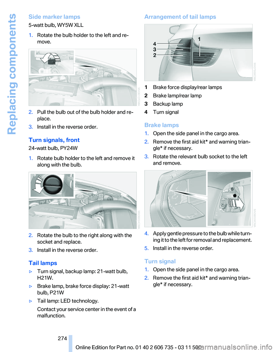
malfunction. Arrangement of tail lamps
1
Brake force display/rear lamps
2 Brake lamp/rear lamp
3 Backup lamp
4 Turn signal
Brake lamps
1. Open the side panel in the cargo area.
2. Remove the first aid kit* and warning trian‐
gle* if necessary.
3. Rotate the relevant bulb socket to the left
and remove. 4.
Apply gentle pressure to the bulb while turn‐
ing
it to the left for removal and replacement.
5. Install in the reverse order.
Turn signal
1. Open the side panel in the cargo area.
2. Remove the first aid kit* and warning trian‐
gle* if necessary.
Seite 274
274 Online Edition for Part no. 01 40 2 606 735 - 03 11 500
Replacing components
Page 275 of 317
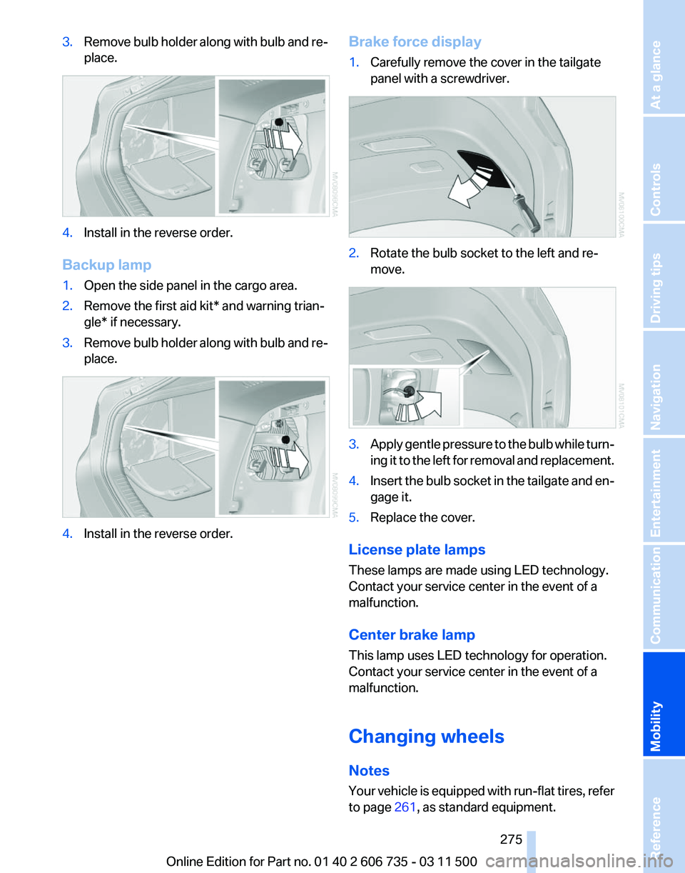
3.
Remove bulb holder along with bulb and re‐
place. 4.
Install in the reverse order.
Backup lamp
1. Open the side panel in the cargo area.
2. Remove the first aid kit* and warning trian‐
gle* if necessary.
3. Remove bulb holder along with bulb and re‐
place. 4.
Install in the reverse order. Brake force display
1.
Carefully remove the cover in the tailgate
panel with a screwdriver. 2.
Rotate the bulb socket to the left and re‐
move. 3.
Apply gentle pressure to the bulb while turn‐
ing
it to the left for removal and replacement.
4. Insert the bulb socket in the tailgate and en‐
gage it.
5. Replace the cover.
License plate lamps
These lamps are made using LED technology.
Contact your service center in the event of a
malfunction.
Center brake lamp
This lamp uses LED technology for operation.
Contact your service center in the event of a
malfunction.
Changing wheels
Notes
Your
vehicle is equipped with run-flat tires, refer
to page 261, as standard equipment.
Seite 275
275Online Edition for Part no. 01 40 2 606 735 - 03 11 500
Reference
Mobility Communication Entertainment Navigation Driving tips Controls At a glance
Page 276 of 317
They do not need to be replaced immediately in
the event of a puncture.
When mounting new tires or changing from
summer
to winter tires or vice versa, use run-flat
tires for your own safety.
BMW X6: do not rotate the front wheels to the
rear or vice versa, as otherwise the handling
characteristics will be negatively affected.
The tools for changing wheels are available as
accessories from your service center.
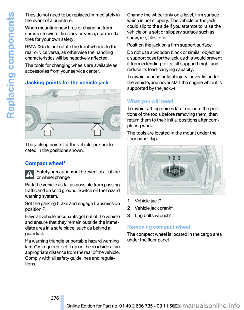
Jacking points for the vehicle jack The jacking points for the vehicle jack are lo‐
cated in the positions shown.
Compact wheel*
Safety
precautions in the event of a flat tire
or wheel change
Park the vehicle as far as possible from passing
traffic and on solid ground. Switch on the hazard
warning system.
Set the parking brake and engage transmission
position P.
Have all vehicle occupants get out of the vehicle
and ensure that they remain outside the imme‐
diate area in a safe place, such as behind a
guardrail.
If a warning triangle or portable hazard warning
lamp* is required, set it up on the roadside at an
appropriate distance from the rear of the vehicle.
Comply with all safety guidelines and regula‐
tions. Change the wheel only on a level, firm surface
which is not slippery. The vehicle or the jack
could slip to the side if you attempt to raise the
vehicle on a soft or slippery surface such as
snow, ice, tiles, etc.
Position the jack on a firm support surface.
Do not use a wooden block or similar object as
a
support base for the jack, as this would prevent
it from extending to its full support height and
reduce its load-carrying capacity.
To avoid serious or fatal injury: never lie under
the vehicle, and never start the engine while it is
supported by the jack.◀
What you will need
To avoid rattling noises later on, note the posi‐
tions of the tools before removing them, then
return them to their initial positions after com‐
pleting work.
The tools are located in the mount under the
floor panel flap. 1
Vehicle jack*
2 Vehicle jack crank*
3 Lug bolts wrench*
Removing compact wheel
The compact wheel is located in the cargo area
under the floor panel.
Seite 276
276 Online Edition for Part no. 01 40 2 606 735 - 03 11 500
Replacing components
Page 277 of 317
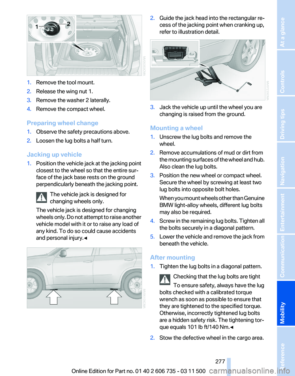
1.
Remove the tool mount.
2. Release the wing nut 1.
3. Remove the washer 2 laterally.
4. Remove the compact wheel.
Preparing wheel change
1. Observe the safety precautions above.
2. Loosen the lug bolts a half turn.
Jacking up vehicle
1. Position the vehicle jack at the jacking point
closest to the wheel so that the entire sur‐
face of the jack base rests on the ground
perpendicularly beneath the jacking point.
The vehicle jack is designed for
changing wheels only.
The vehicle jack is designed for changing
wheels
only. Do not attempt to raise another
vehicle model with it or to raise any load of
any kind. To do so could cause accidents
and personal injury.◀ 2.
Guide the jack head into the rectangular re‐
cess of the jacking point when cranking up,
refer to illustration detail. 3.
Jack the vehicle up until the wheel you are
changing is raised from the ground.
Mounting a wheel
1. Unscrew the lug bolts and remove the
wheel.
2. Remove accumulations of mud or dirt from
the
mounting surfaces of the wheel and hub.
Also clean the lug bolts.
3. Position the new wheel or compact wheel.
Secure the wheel by screwing at least two
lug bolts into opposite bolt holes.
When
you mount wheels other than Genuine
BMW light-alloy wheels, different lug bolts
may also be required.
4. Screw in the remaining lug bolts. Tighten all
the bolts securely in a diagonal pattern.
5. Lower the vehicle and remove the jack from
beneath the vehicle.
After mounting
1. Tighten the lug bolts in a diagonal pattern.
Checking that the lug bolts are tight
To ensure safety, always have the lug
bolts checked with a calibrated torque
wrench as soon as possible to ensure that
they are tightened to the specified torque.
Otherwise, incorrectly tightened lug bolts
are a hidden safety risk. The tightening tor‐
que equals 101 lb ft/140 Nm.
◀ 2.
Stow the defective wheel in the cargo area.
Seite 277
277Online Edition for Part no. 01 40 2 606 735 - 03 11 500
Reference
Mobility Communication Entertainment Navigation Driving tips Controls At a glance
Page 278 of 317
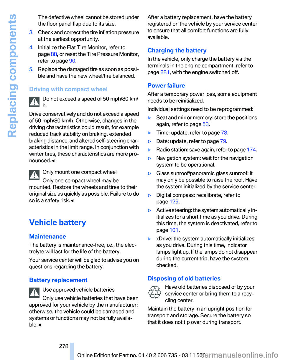
The defective wheel cannot be stored under
the floor panel flap due to its size.
3. Check and correct the tire inflation pressure
at the earliest opportunity.
4. Initialize the Flat Tire Monitor, refer to
page 88,
or reset the Tire Pressure Monitor,
refer to page 90.
5. Replace the damaged tire as soon as possi‐
ble and have the new wheel/tire balanced.
Driving with compact wheel Do not exceed a speed of 50 mph/80 km/
h.
Drive
conservatively and do not exceed a speed
of 50 mph/80 km/h. Otherwise, changes in the
driving characteristics could result, for example
reduced track stability on braking, extended
braking distance, and altered self-steering char‐
acteristics in the limit range. In conjunction with
winter tires, these characteristics are more pro‐
nounced.◀
Only mount one compact wheel
Only one compact wheel may be
mounted. Restore the wheels and tires to their
original size as quickly as possible. Failure to do
so is a safety risk.◀
Vehicle battery
Maintenance
The battery is maintenance-free, i.e., the elec‐
trolyte will last for the life of the battery.
Your service center will be glad to advise you on
questions regarding the battery.
Battery replacement
Use approved vehicle batteries
Only use vehicle batteries that have been
approved for your vehicle by the manufacturer;
otherwise, the vehicle could be damaged and
systems or functions may not be fully availa‐
ble.◀ After a battery replacement, have the battery
registered
on the vehicle by your service center
to ensure that all comfort functions are fully
available.
Charging the battery
In the vehicle, only charge the battery via the
terminals in the engine compartment, refer to
page 281, with the engine switched off.
Power failure
After a temporary power loss, some equipment
needs to be reinitialized.
Individual settings need to be reprogrammed:
▷ Seat and mirror memory: store the positions
again, refer to page 53.
▷ Time: update, refer to page 78.
▷ Date: update, refer to page 79.
▷ Radio station: save again, refer to page 174.
▷ Navigation system: wait for the navigation
system to be operational.
▷ Glass sunroof/panoramic glass sunroof: it
may
only be possible to raise the roof. Have
the system initialized by the service center.
▷ Digital compass: recalibrate, refer to
page 129.
▷ Active steering: the system automatically in‐
itializes for a short time as you drive. During
this
time, the system is deactivated, refer to
page 101.
▷ xDrive: the system automatically initializes
as you drive. During this time, indicator
lamps
light up. If the lamps do not disappear
during the current trip, have the system
checked.
Disposing of old batteries Have old batteries disposed of by your
service center or bring them to a recy‐
cling center.
Maintain the battery in an upright position for
transport and storage. Secure the battery so
that it does not tip over during transport. Seite 278
278 Online Edition for Part no. 01 40 2 606 735 - 03 11 500
Replacing components
Page 279 of 317
Fuses
Replacing fuses
Never attempt to repair a blown fuse and
do
not replace a defective fuse with a substitute
of another color or amperage rating; this could
lead to a circuit overload, ultimately resulting in
a fire in the vehicle.◀
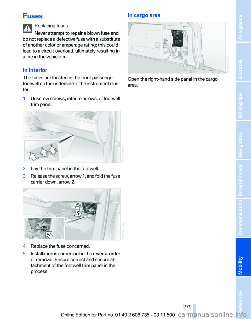
In interior
The fuses are located in the front passenger
footwell on the underside of the instrument clus‐
ter.
1. Unscrew screws, refer to arrows, of footwell
trim panel. 2.
Lay the trim panel in the footwell.
3. Release the screw, arrow 1, and fold the fuse
carrier down, arrow 2. 4.
Replace the fuse concerned.
5. Installation is carried out in the reverse order
of removal. Ensure correct and secure at‐
tachment of the footwell trim panel in the
process. In cargo area
Open the right-hand side panel in the cargo
area.
Seite 279
279Online Edition for Part no. 01 40 2 606 735 - 03 11 500
Reference
Mobility Communication Entertainment Navigation Driving tips Controls At a glance
Page 280 of 317
Breakdown assistance
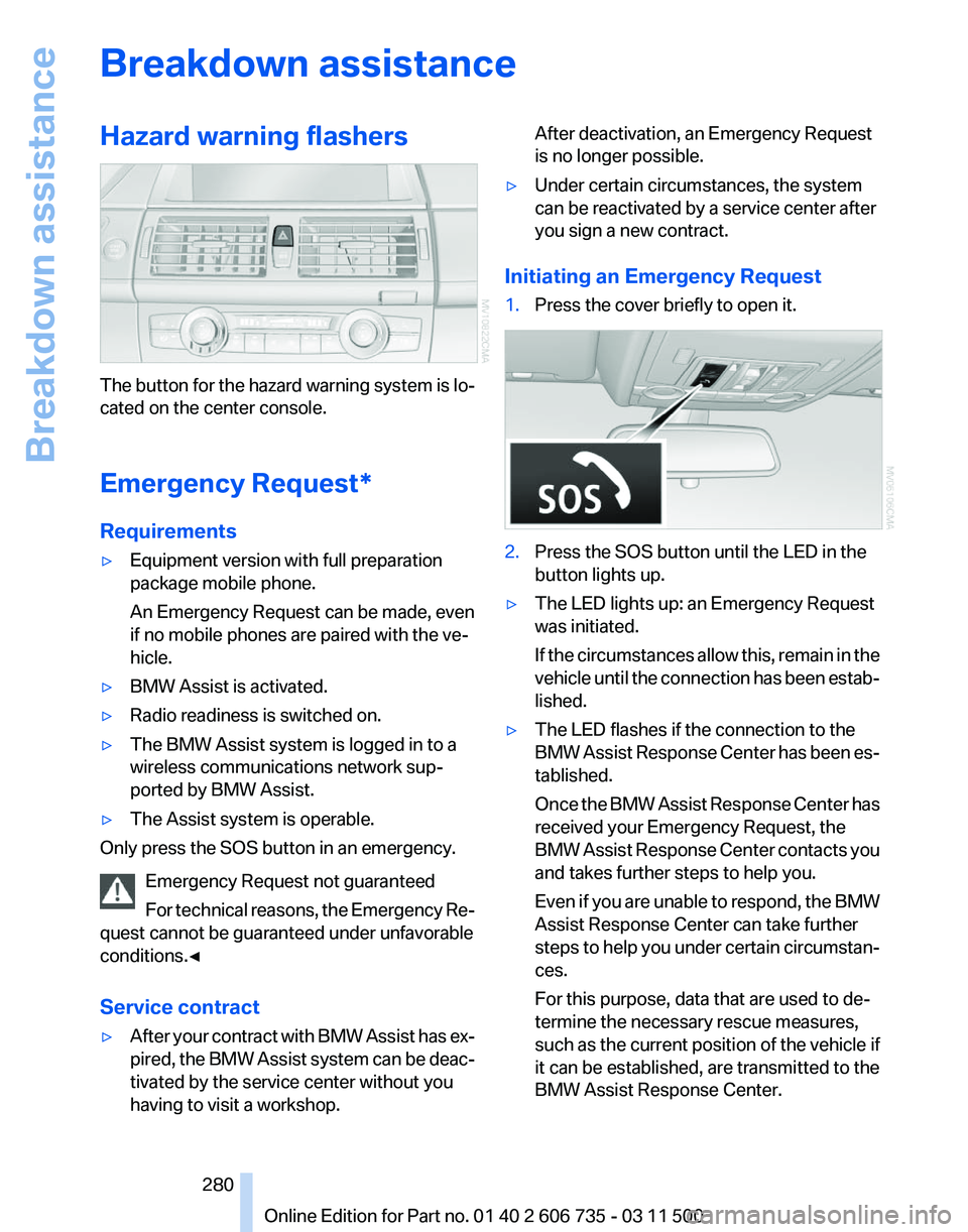
Hazard warning flashers
The button for the hazard warning system is lo‐
cated on the center console.
Emergency Request
*
Requirements
▷ Equipment version with full preparation
package mobile phone.
An Emergency Request can be made, even
if no mobile phones are paired with the ve‐
hicle.
▷ BMW Assist is activated.
▷ Radio readiness is switched on.
▷ The BMW Assist system is logged in to a
wireless communications network sup‐
ported by BMW Assist.
▷ The Assist system is operable.
Only press the SOS button in an emergency.
Emergency Request not guaranteed
For
technical reasons, the Emergency Re‐
quest cannot be guaranteed under unfavorable
conditions.◀
Service contract
▷ After your contract with BMW Assist has ex‐
pired,
the BMW Assist system can be deac‐
tivated by the service center without you
having to visit a workshop. After deactivation, an Emergency Request
is no longer possible.
▷ Under certain circumstances, the system
can be reactivated by a service center after
you sign a new contract.
Initiating an Emergency Request
1. Press the cover briefly to open it. 2.
Press the SOS button until the LED in the
button lights up.
▷ The LED lights up: an Emergency Request
was initiated.
If
the circumstances allow this, remain in the
vehicle until the connection has been estab‐
lished.
▷ The LED flashes if the connection to the
BMW
Assist Response Center has been es‐
tablished.
Once the BMW Assist Response Center has
received your Emergency Request, the
BMW Assist Response Center contacts you
and takes further steps to help you.
Even if you are unable to respond, the BMW
Assist Response Center can take further
steps to help you under certain circumstan‐
ces.
For this purpose, data that are used to de‐
termine the necessary rescue measures,
such as the current position of the vehicle if
it can be established, are transmitted to the
BMW Assist Response Center.
Seite 280
280 Online Edition for Part no. 01 40 2 606 735 - 03 11 500
Breakdown assistance