warning BMW X5 XDRIVE35D 2012 Owners Manual
[x] Cancel search | Manufacturer: BMW, Model Year: 2012, Model line: X5 XDRIVE35D, Model: BMW X5 XDRIVE35D 2012Pages: 317, PDF Size: 8.83 MB
Page 7 of 317
Therefore, have this work performed only by a
BMW center or a workshop that works accord‐
ing to BMW repair procedures with appropri‐
ately trained personnel.
If this work is not carried out properly, there is
the danger of subsequent damage and related
safety hazards.
Parts and accessories
For your own safety, use genuine parts and ac‐
cessories approved by BMW. When you pur‐
chase accessories tested and approved by
BMW and Genuine BMW Parts, you simultane‐
ously
acquire the assurance that they have been
thoroughly tested by BMW to ensure optimum
performance when installed on your vehicle.
BMW warrants these parts to be free from de‐
fects in material and workmanship. BMW will not
accept any liability for damage resulting from in‐
stallation of parts and accessories not approved
by BMW. BMW cannot test every product made
by other manufacturers to verify if it can be used
on a BMW safely and without risk to either the
vehicle, its operation, or its occupants. Genuine
BMW Parts, BMW Accessories and other prod‐
ucts approved by BMW, together with profes‐
sional advice on using these items, are available
from all BMW centers. Installation and operation
of non-BMW approved accessories such as
alarms, radios, amplifiers, radar detectors,
wheels, suspension components, brake dust
shields, telephones, including operation of any
mobile phone from within the vehicle without
using an externally mounted antenna, or trans‐
ceiver equipment, for instance, CBs, walkie-
talkies, ham radios or similar accessories, may
cause extensive damage to the vehicle, com‐
promise its safety, interfere with the vehicle's
electrical system or affect the validity of the
BMW Limited Warranty. See your BMW center
for additional information. Maintenance, re‐
placement, or repair of the emission control de‐
vices and systems may be performed by any au‐
tomotive repair establishment or individual
using any certified automotive part. California Proposition 65 Warning
California laws require us to state the following
warning:
Engine
exhaust and a wide variety of automobile
components and parts, including components
found in the interior furnishings in a vehicle, con‐
tain or emit chemicals known to the State of Cal‐
ifornia to cause cancer and birth defects and re‐
productive harm. In addition, certain fluids
contained in vehicles and certain products of
component wear contain or emit chemicals
known to the State of California to cause cancer
and birth defects or other reproductive harm.
Battery posts, terminals and related accessories
contain lead and lead compounds. Wash your
hands after handling. Used engine oil contains
chemicals that have caused cancer in laboratory
animals. Always protect your skin by washing
thoroughly with soap and water.
Service and warranty
We recommend that you read this publication
thoroughly. Your vehicle is covered by the fol‐
lowing warranties:
▷ New Vehicle Limited Warranty
▷ Rust Perforation Limited Warranty
▷ Federal Emissions System Defect Warranty
▷ Federal Emissions Performance Warranty
▷ California Emission Control System Limited
Warranty
Detailed information about these warranties is
listed in the Service and Warranty Information
Booklet for US models or in the Warranty and
Service Guide Booklet for Canadian models.
Your vehicle has been specifically adapted and
designed to meet the particular operating con‐
ditions and homologation requirements in your
country
and continental region in order to deliver
the full driving pleasure while the vehicle is op‐
erated under those conditions. If you wish to op‐
erate your vehicle in another country or region,
you may be required to adapt your vehicle to
meet different prevailing operating conditions
and homologation requirements. You should
also be aware of any applicable warranty limita‐
tions or exclusions for such country or region. In
Seite 7
7Online Edition for Part no. 01 40 2 606 735 - 03 11 500
Reference Mobility Communication Entertainment Navigation Driving tips Controls At a glance
Page 13 of 317
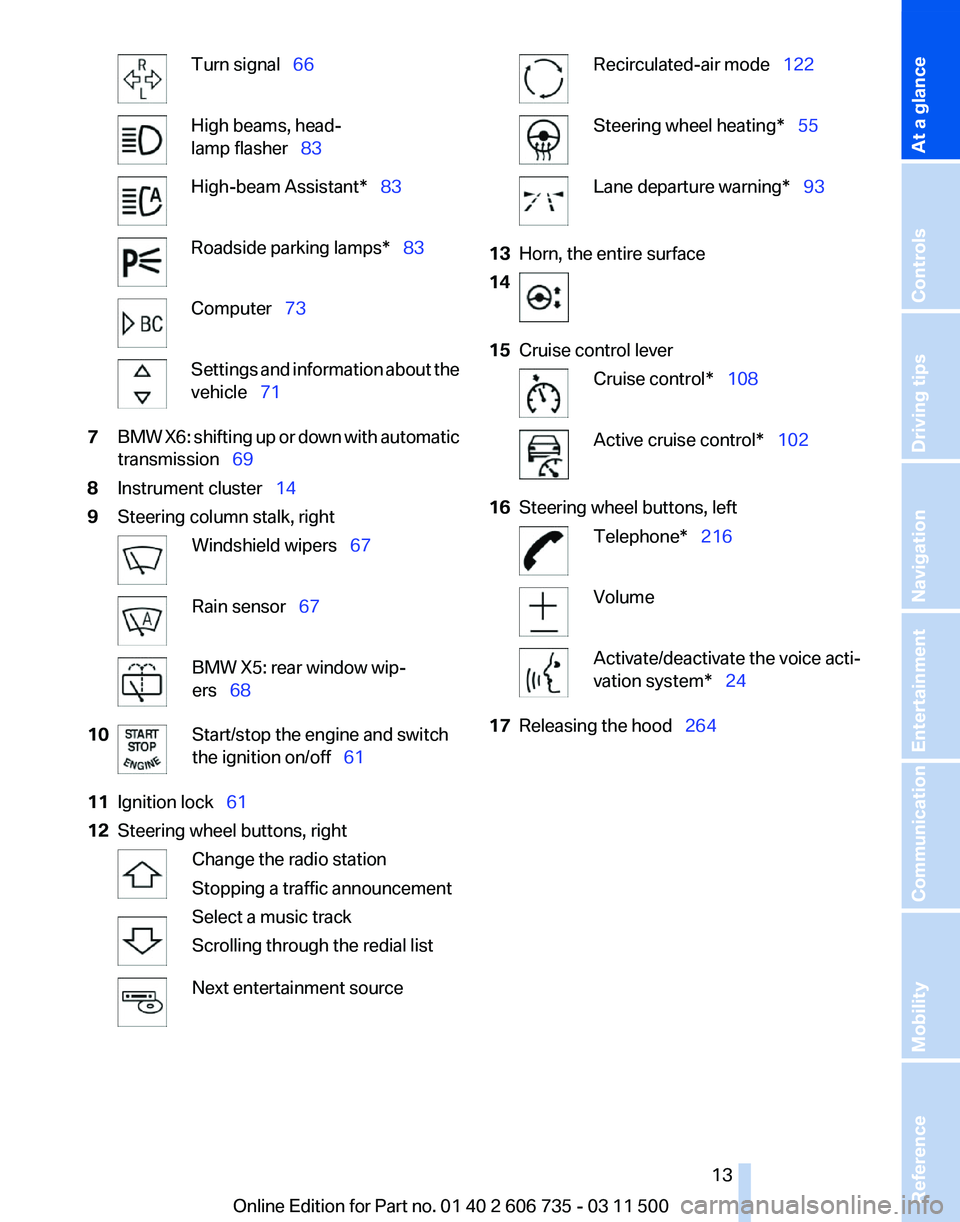
Turn signal 66
High beams, head‐
lamp flasher 83
High-beam Assistant* 83
Roadside parking lamps* 83
Computer 73
Settings and information about the
vehicle 71
7 BMW X6: shifting up or down with automatic
transmission 69
8 Instrument cluster 14
9 Steering column stalk, right Windshield wipers 67
Rain sensor
67 BMW X5: rear window wip‐
ers 68
10 Start/stop the engine and switch
the ignition on/off 61
11 Ignition lock 61
12 Steering wheel buttons, right Change the radio station
Stopping a traffic announcement
Select a music track
Scrolling through the redial list
Next entertainment source Recirculated-air mode 122
Steering wheel heating* 55
Lane departure warning* 93
13 Horn, the entire surface
14 15
Cruise control lever Cruise control*
108 Active cruise control*
102
16 Steering wheel buttons, left Telephone* 216
Volume
Activate/deactivate the voice acti‐
vation system* 24
17 Releasing the hood 264
Seite 13
13Online Edition for Part no. 01 40 2 606 735 - 03 11 500
Reference Mobility Communication Entertainment Navigation Driving tips Controls
At a glance
Page 14 of 317
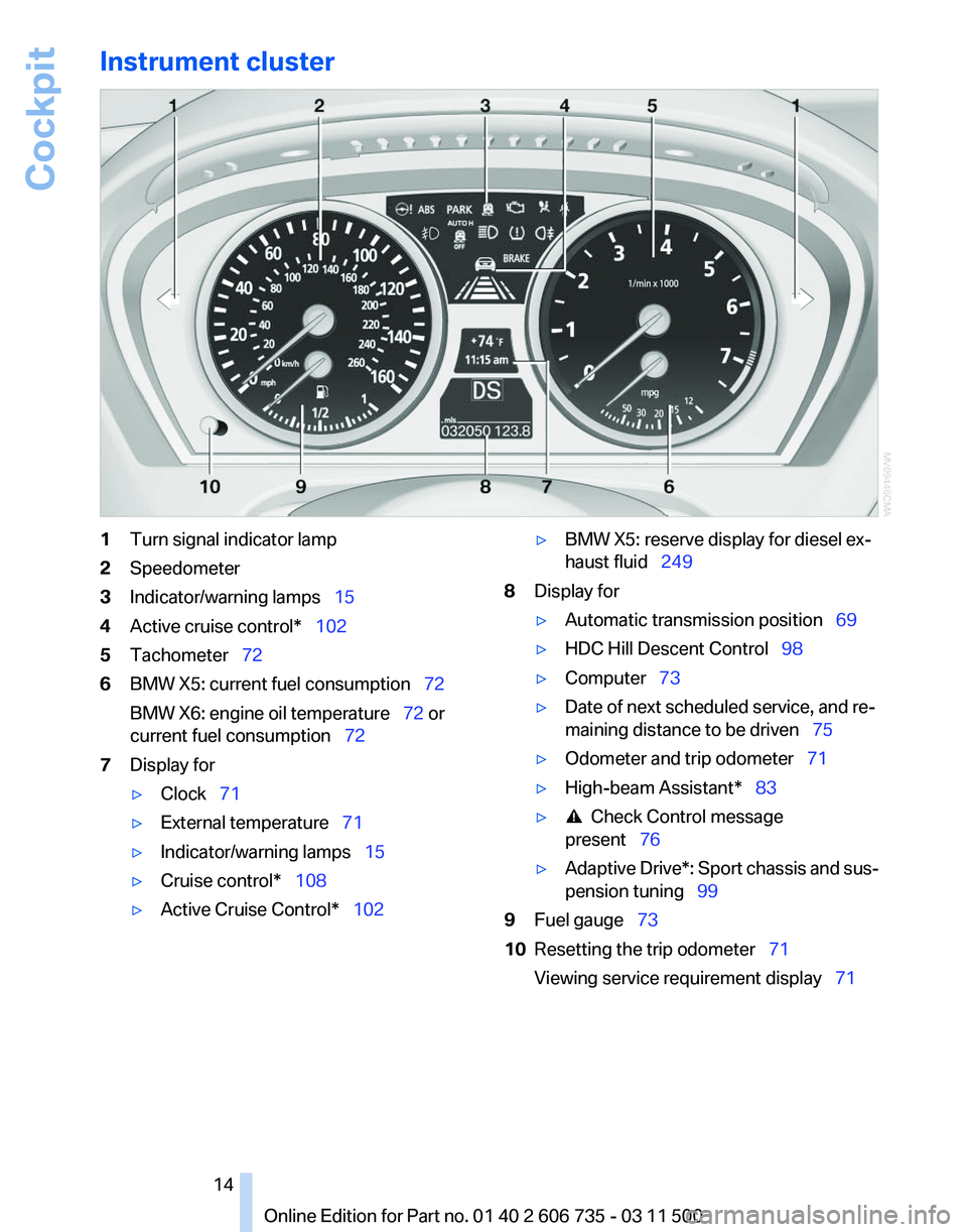
Instrument cluster
1
Turn signal indicator lamp
2 Speedometer
3 Indicator/warning lamps 15
4 Active cruise control* 102
5 Tachometer 72
6 BMW X5: current fuel consumption 72
BMW X6: engine oil temperature
72 or
current fuel consumption 72
7 Display for
▷Clock 71
▷ External temperature 71
▷ Indicator/warning lamps 15
▷ Cruise control* 108
▷ Active Cruise Control* 102 ▷
BMW X5: reserve display for diesel ex‐
haust fluid 249
8 Display for
▷Automatic transmission position 69
▷ HDC Hill Descent Control 98
▷ Computer 73
▷ Date of next scheduled service, and re‐
maining distance to be driven
75
▷ Odometer and trip odometer 71
▷ High-beam Assistant* 83
▷ Check Control message
present 76
▷ Adaptive Drive*:
Sport chassis and sus‐
pension tuning 99
9 Fuel gauge 73
10 Resetting the trip odometer 71
Viewing service requirement display 71
Seite 14
14 Online Edition for Part no. 01 40 2 606 735 - 03 11 500
Cockpit
Page 15 of 317
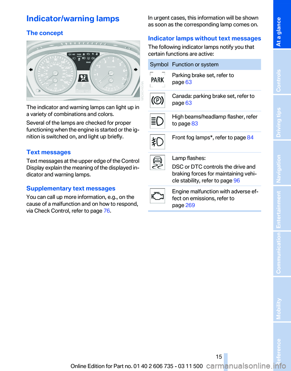
Indicator/warning lamps
The concept
The indicator and warning lamps can light up in
a variety of combinations and colors.
Several of the lamps are checked for proper
functioning
when the engine is started or the ig‐
nition is switched on, and light up briefly.
Text messages
Text messages at the upper edge of the Control
Display explain the meaning of the displayed in‐
dicator and warning lamps.
Supplementary text messages
You can call up more information, e.g., on the
cause of a malfunction and on how to respond,
via Check Control, refer to page 76.In urgent cases, this information will be shown
as soon as the corresponding lamp comes on.
Indicator lamps without text messages
The following indicator lamps notify you that
certain functions are active: Symbol Function or system
Parking brake set, refer to
page
63 Canada: parking brake set, refer to
page
63 High beams/headlamp flasher, refer
to page
83 Front fog lamps*, refer to page
84 Lamp flashes:
DSC or DTC controls the drive and
braking forces for maintaining vehi‐
cle stability, refer to page
96 Engine malfunction with adverse ef‐
fect on emissions, refer to
page
269 Seite 15
15Online Edition for Part no. 01 40 2 606 735 - 03 11 500
Reference Mobility Communication Entertainment Navigation Driving tips Controls
At a glance
Page 16 of 317
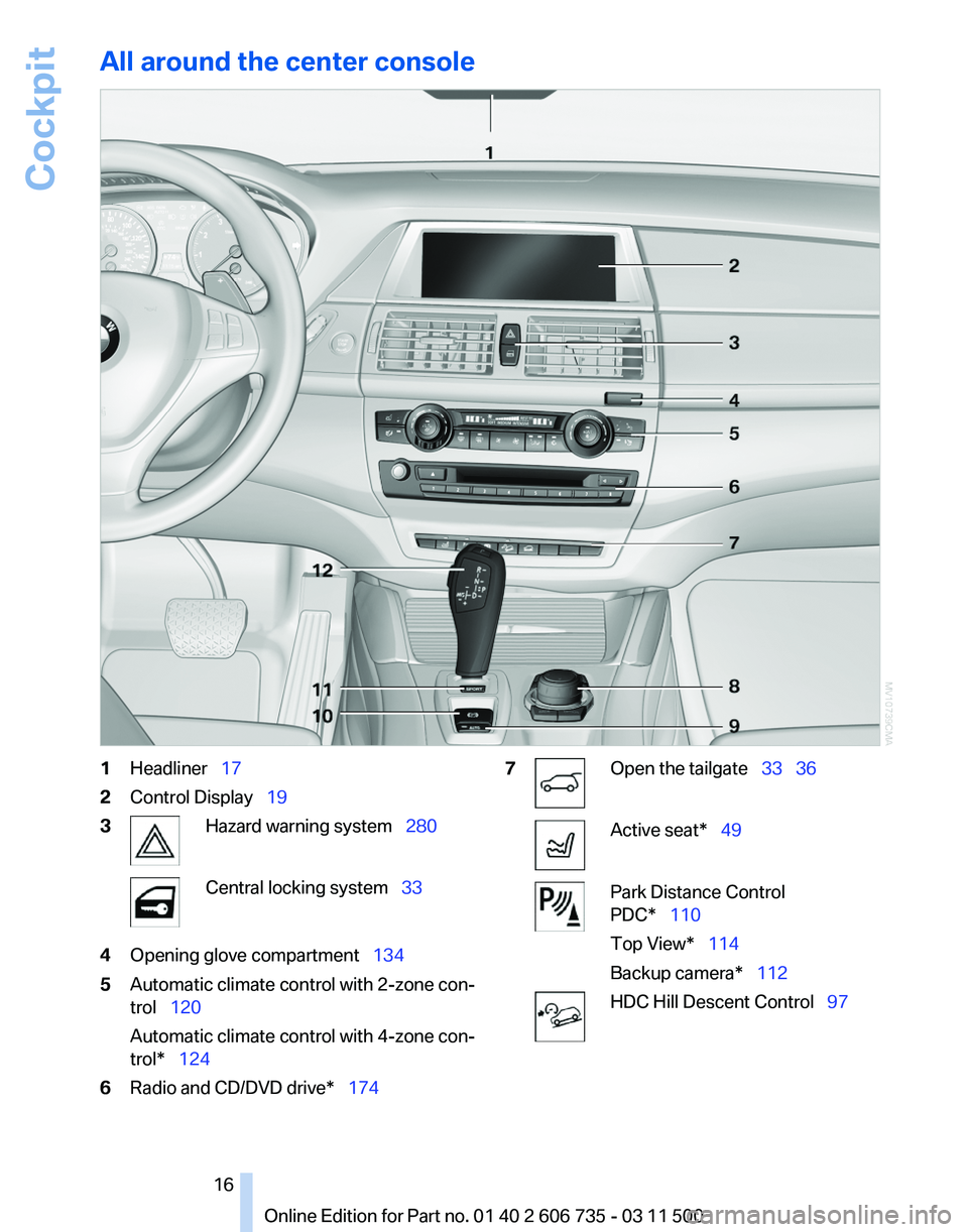
All around the center console
1
Headliner 17
2 Control Display 19
3 Hazard warning system 280
Central locking system 33
4 Opening glove compartment 134
5 Automatic climate control with 2-zone con‐
trol 120
Automatic climate control with 4-zone con‐
trol* 124
6 Radio and CD/DVD drive* 174 7 Open the tailgate
33 36 Active seat* 49
Park Distance Control
PDC* 110
Top View* 114
Backup camera* 112
HDC Hill Descent Control
97
Seite 16
16 Online Edition for Part no. 01 40 2 606 735 - 03 11 500Cockpit
Page 29 of 317
The individual settings are stored for a maximum
of
four remote controls. They are stored for two
remote controls if Comfort Access* is in use.
Personal Profile settings
The following functions and settings can be
stored in a profile.
More information on the settings can be found
under:
▷ Assigning the programmable memory but‐
tons, refer to page 22.
▷ Response of the central locking system
when the car is being unlocked, refer to
page 30.
▷ Automatic locking of the vehicle, refer to
page 33.
▷ Driver's seat, exterior mirror and steering
wheel positions*, refer to page 53.
▷ Settings for the display on the Control Dis‐
play and in the instrument cluster:
▷12h/24h clock format, refer to
page 79.
▷ Date format, refer to page 79.
▷ Brightness of the Control Display, refer
to page 80.
▷ Language on the Control Display, refer
to page 80.
▷ Units of measure for fuel consumption,
distance covered/remaining distances,
and temperature, refer to page 80.
▷ Show visual warning for the Park Distance
Control PDC*, refer to page 111.
▷ Show visual warning for Top View*, refer to
page 114.
▷ Show Side View*, refer to page 116.
▷ Backup camera*:
▷Function selection, refer to page 113.
▷ Type of display, refer to page 114.
▷ Lane departure warning*: last setting, on/
off, refer to page 93.
▷ Head-up Display*: selection, brightness and
position of the display, refer to page 117.▷
Adaptive Drive*: selected chassis and sus‐
pension tuning, refer to page 99.
▷ Light settings:
▷Triple turn signal activation, refer to
page 66.
▷ Welcome lamps, refer to page 81.
▷ Headlamp courtesy delay feature, refer
to page 81.
▷ Daytime running lights, refer to
page 82.
▷ High-beam Assistant*, refer to
page 83.
▷ Automatic climate control with 2-zone con‐
trol: settings, refer to page 120.
▷ Navigation:
▷Voice activation, refer to page 163.
▷ Route criteria, refer to page 161.
▷ Map view settings, refer to page 164.
▷ Entertainment:
▷Tone control, refer to page 172.
▷ Radio, stored stations, refer to
page 180.
▷ CD/multimedia, audio source listened to
last, refer to page 181.
▷ Telephone: volume, refer to page 220.
Central locking system
The concept
The central locking system becomes active
when the driver's door is closed.
The system simultaneously engages and re‐
leases the locks on the following:
▷ Doors.
▷ Tailgate.
▷ Fuel filler flap.
Operating from the outside
▷ Via the remote control.
▷ Via the door lock*.
Seite 29
29Online Edition for Part no. 01 40 2 606 735 - 03 11 500
Reference Mobility Communication Entertainment Navigation Driving tips
Controls At a glance
Page 30 of 317
▷
In cars with Comfort Access*, via the door
handles.
The following takes place simultaneously when
locking/unlocking the vehicle via the remote
control:
▷ The welcome lamps, interior lamps and
courtesy lamps* are switched on and off.
▷ The alarm system* is armed or disarmed,
refer to page 39.
Operating from the inside
Via the button for the central locking system, re‐
fer to page 33.
If the vehicle is locked from the inside, the fuel
filler flap remains unlocked.
If an accident of a certain severity occurs, the
central locking system unlocks automatically.
The hazard warning system and interior lamps
come on.
Opening and closing: from the
outside
Using the remote control
General information
Take the remote control with you
People or animals left unattended in a
parked vehicle can lock the doors from the in‐
side. Always take the remote control with you
when leaving the vehicle so that the vehicle can
then be opened from the outside.◀
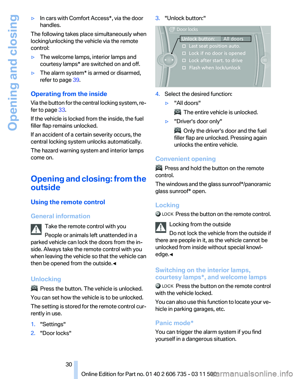
Unlocking Press the button. The vehicle is unlocked.
You can set how the vehicle is to be unlocked.
The
setting is stored for the remote control cur‐
rently in use.
1. "Settings"
2. "Door locks" 3.
"Unlock button:" 4.
Select the desired function:
▷"All doors" The entire vehicle is unlocked.
▷ "Driver's door only" Only the driver's door and the fuel
filler flap are unlocked. Pressing again
unlocks the entire vehicle.
Convenient opening Press and hold the button on the remote
control.
The
windows and the glass sunroof*/panoramic
glass sunroof* open.
Locking Press the button on the remote control.
Locking from the outside
Do
not lock the vehicle from the outside if
there are people in it, as the vehicle cannot be
unlocked from inside without special knowl‐
edge.◀
Switching on the interior lamps,
courtesy lamps*, and welcome lamps Press
the button on the remote control
with the vehicle locked.
You can also use this function to locate your ve‐
hicle in parking garages, etc.
Panic mode*
You can trigger the alarm system if you find
yourself in a dangerous situation. Seite 30
30 Online Edition for Part no. 01 40 2 606 735 - 03 11 500
Opening and closing
Page 38 of 317
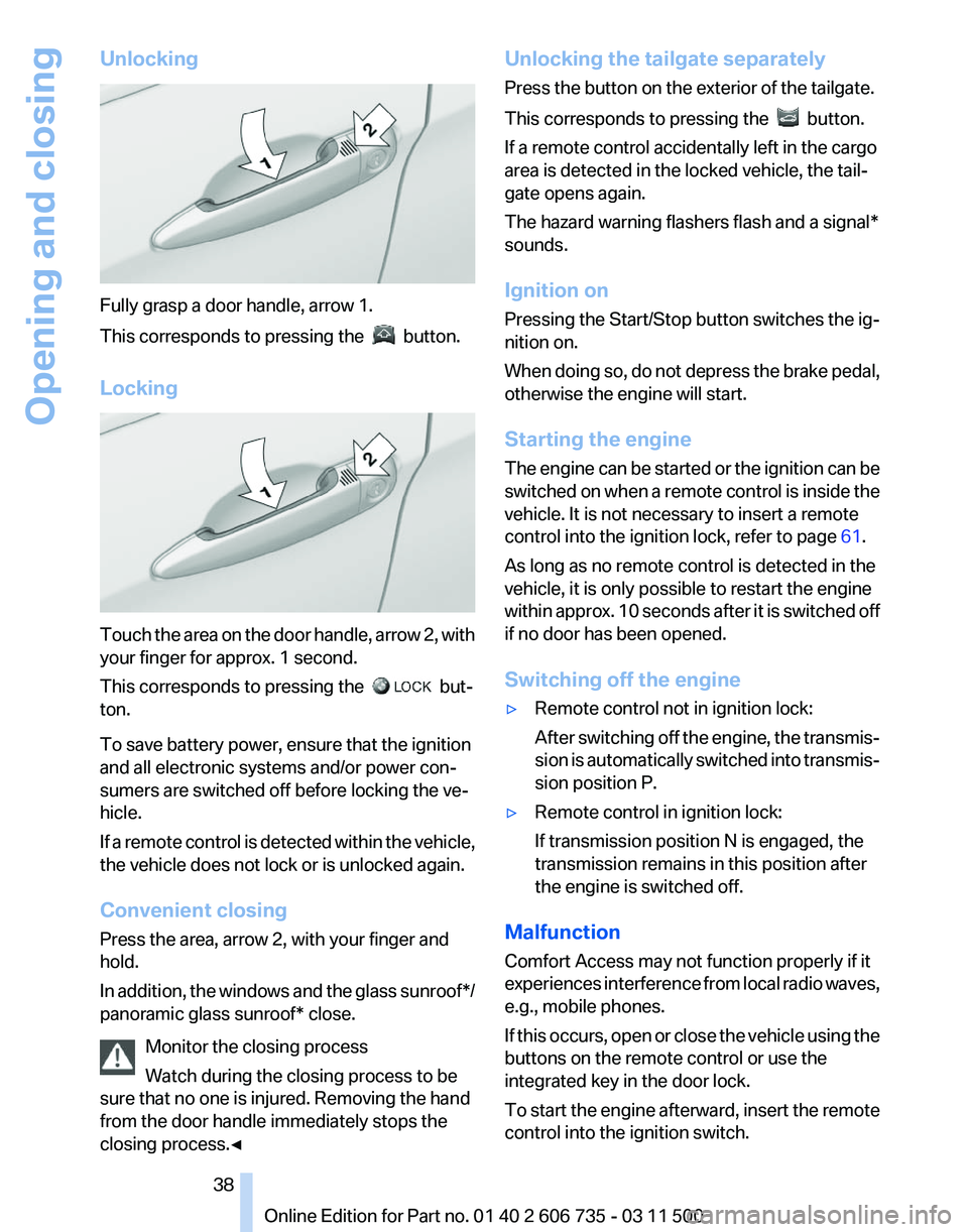
Unlocking
Fully grasp a door handle, arrow 1.
This corresponds to pressing the
button.
Locking Touch the area on the door handle, arrow 2, with
your finger for approx. 1 second.
This corresponds to pressing the
but‐
ton.
To save battery power, ensure that the ignition
and all electronic systems and/or power con‐
sumers are switched off before locking the ve‐
hicle.
If
a remote control is detected within the vehicle,
the vehicle does not lock or is unlocked again.
Convenient closing
Press the area, arrow 2, with your finger and
hold.
In addition, the windows and the glass sunroof*/
panoramic glass sunroof* close.
Monitor the closing process
Watch during the closing process to be
sure that no one is injured. Removing the hand
from the door handle immediately stops the
closing process.◀ Unlocking the tailgate separately
Press the button on the exterior of the tailgate.
This corresponds to pressing the
button.
If a remote control accidentally left in the cargo
area is detected in the locked vehicle, the tail‐
gate opens again.
The hazard warning flashers flash and a signal*
sounds.
Ignition on
Pressing the Start/Stop button switches the ig‐
nition on.
When
doing so, do not depress the brake pedal,
otherwise the engine will start.
Starting the engine
The engine can be started or the ignition can be
switched on when a remote control is inside the
vehicle. It is not necessary to insert a remote
control into the ignition lock, refer to page 61.
As long as no remote control is detected in the
vehicle, it is only possible to restart the engine
within approx. 10 seconds after it is switched off
if no door has been opened.
Switching off the engine
▷ Remote control not in ignition lock:
After
switching off the engine, the transmis‐
sion is automatically switched into transmis‐
sion position P.
▷ Remote control in ignition lock:
If transmission position N is engaged, the
transmission remains in this position after
the engine is switched off.
Malfunction
Comfort Access may not function properly if it
experiences
interference from local radio waves,
e.g., mobile phones.
If this occurs, open or close the vehicle using the
buttons on the remote control or use the
integrated key in the door lock.
To start the engine afterward, insert the remote
control into the ignition switch.
Seite 38
38 Online Edition for Part no. 01 40 2 606 735 - 03 11 500
Opening and closing
Page 39 of 317
Warning lamps
The warning lamp in the instrument
cluster lights up when you attempt to
start
the engine: the engine cannot be
started.
The remote control is not in the vehicle or has a
malfunction. Take the remote control with you
inside the vehicle or have it checked. If neces‐
sary, insert another remote control into the ig‐
nition switch.
The warning lamp in the instrument
cluster lights up while the engine is
running: the remote control is no lon‐
ger inside the vehicle.
After switching off the engine, the engine can
only be started again within approx. 10 seconds
if no door has been opened.
The indicator lamp in the instrument
cluster comes on and a message ap‐
pears on the Control Display: replace
the remote control battery.
Replacing the battery
The remote control for Comfort Access con‐
tains a battery that will need to be replaced from
time to time.
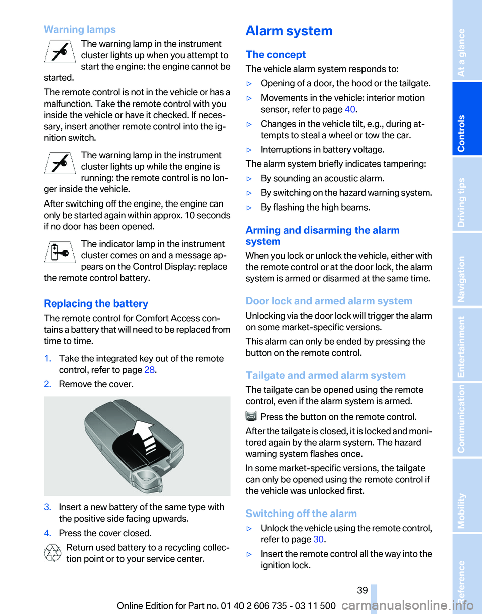
1. Take the integrated key out of the remote
control, refer to page 28.
2. Remove the cover. 3.
Insert a new battery of the same type with
the positive side facing upwards.
4. Press the cover closed.
Return used battery to a recycling collec‐
tion point or to your service center. Alarm system
The concept
The vehicle alarm system responds to:
▷
Opening of a door, the hood or the tailgate.
▷ Movements in the vehicle: interior motion
sensor, refer to page 40.
▷ Changes in the vehicle tilt, e.g., during at‐
tempts to steal a wheel or tow the car.
▷ Interruptions in battery voltage.
The alarm system briefly indicates tampering:
▷ By sounding an acoustic alarm.
▷ By switching on the hazard warning system.
▷ By flashing the high beams.
Arming and disarming the alarm
system
When
you lock or unlock the vehicle, either with
the remote control or at the door lock, the alarm
system is armed or disarmed at the same time.
Door lock and armed alarm system
Unlocking via the door lock will trigger the alarm
on some market-specific versions.
This alarm can only be ended by pressing the
button on the remote control.
Tailgate and armed alarm system
The tailgate can be opened using the remote
control, even if the alarm system is armed. Press the button on the remote control.
After
the tailgate is closed, it is locked and moni‐
tored again by the alarm system. The hazard
warning system flashes once.
In some market-specific versions, the tailgate
can only be opened using the remote control if
the vehicle was unlocked first.
Switching off the alarm
▷ Unlock the vehicle using the remote control,
refer to page 30.
▷ Insert the remote control all the way into the
ignition lock.
Seite 39
39Online Edition for Part no. 01 40 2 606 735 - 03 11 500
Reference Mobility Communication Entertainment Navigation Driving tips
Controls At a glance
Page 47 of 317
Press upper or lower section of switch.
BMW X5: rear seats
2nd row seats
If the row of seats is divided
*, each side can be
adjusted separately.
Do not adjust the seat while driving
Never adjust the 2nd row seats while the
vehicle is moving, as otherwise the passengers
on the 3rd row seats could be injured.
Make sure that the locking devices of the 2nd
row seats engage properly. Otherwise the re‐
straining effect of the safety belts during an ac‐
cident could be reduced.◀
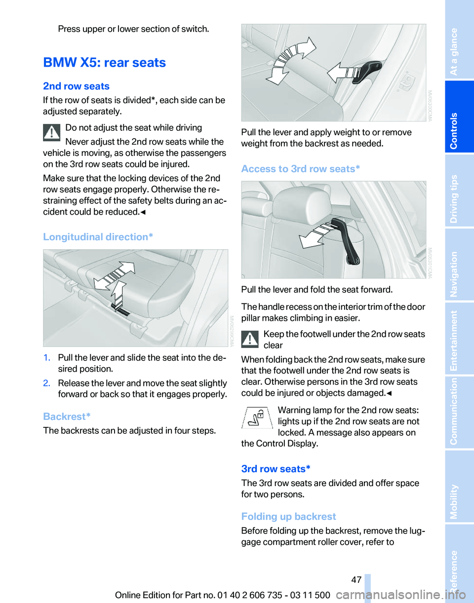
Longitudinal direction* 1.
Pull the lever and slide the seat into the de‐
sired position.
2. Release the lever and move the seat slightly
forward or back so that it engages properly.
Backrest*
The backrests can be adjusted in four steps. Pull the lever and apply weight to or remove
weight from the backrest as needed.
Access to 3rd row seats*
Pull the lever and fold the seat forward.
The
handle recess on the interior trim of the door
pillar makes climbing in easier.
Keep the footwell under the 2nd row seats
clear
When folding back the 2nd row seats, make sure
that the footwell under the 2nd row seats is
clear. Otherwise persons in the 3rd row seats
could be injured or objects damaged.◀
Warning lamp for the 2nd row seats:
lights up if the 2nd row seats are not
locked. A message also appears on
the Control Display.
3rd row seats*
The 3rd row seats are divided and offer space
for two persons.
Folding up backrest
Before folding up the backrest, remove the lug‐
gage compartment roller cover, refer to Seite 47
47Online Edition for Part no. 01 40 2 606 735 - 03 11 500
Reference Mobility Communication Entertainment Navigation Driving tips
Controls At a glance