mirror BMW X6 2013 E71 User Guide
[x] Cancel search | Manufacturer: BMW, Model Year: 2013, Model line: X6, Model: BMW X6 2013 E71Pages: 327, PDF Size: 7.71 MB
Page 70 of 327
Rain sensorIf the car is equipped with a rain sensor, the
time between wipes is controlled automatically
and depends on the intensity of the rainfall.
The rain sensor is mounted on the windshield,
directly in front of the interior rearview mirror.
Activating the rain sensor
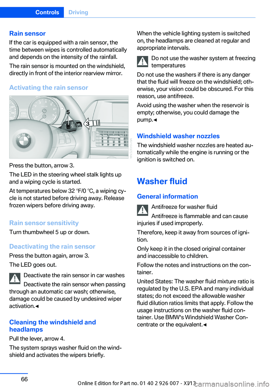
Press the button, arrow 3.
The LED in the steering wheel stalk lights up
and a wiping cycle is started.
At temperatures below 32 ℉/0 ℃, a wiping cy‐
cle is not started before driving away. Release
frozen wipers before driving away.
Rain sensor sensitivity Turn thumbwheel 5 up or down.
Deactivating the rain sensor
Press the button again, arrow 3.
The LED goes out.
Deactivate the rain sensor in car washes
Deactivate the rain sensor when passing
through an automatic car wash; otherwise,
damage could be caused by undesired wiper
activation.◀
Cleaning the windshield and
headlamps
Pull the lever, arrow 4.
The system sprays washer fluid on the wind‐
shield and activates the wipers briefly.
When the vehicle lighting system is switched
on, the headlamps are cleaned at regular and
appropriate intervals.
Do not use the washer system at freezing
temperatures
Do not use the washers if there is any danger
that the fluid will freeze on the windshield; oth‐
erwise, your vision could be obscured. For this
reason, use antifreeze.
Avoid using the washer when the reservoir is
empty; otherwise, you could damage the
pump.◀
Windshield washer nozzles
The windshield washer nozzles are heated au‐
tomatically while the engine is running or the
ignition is switched on.
Washer fluid General information Antifreeze for washer fluid
Antifreeze is flammable and can cause
injuries if used improperly.
Therefore, keep it away from sources of igni‐
tion.
Only keep it in the closed original container
and inaccessible to children.
Follow the notes and instructions on the con‐
tainer.
United States: The washer fluid mixture ratio is
regulated by the U.S. EPA and many individual
states; do not exceed the allowable washer
fluid dilution ratios limits that apply. Follow the
usage instructions on the washer fluid con‐
tainer. Use BMW's Windshield Washer Con‐
centrate or the equivalent.◀Seite 66ControlsDriving66
Online Edition for Part no. 01 40 2 910 876 - VII/13
Page 87 of 327
Controls
Activating Switch position
with the ignition switched
on.
The turning lamps are automatically switched
on depending on the steering angle or the use
of turn signals.
To avoid blinding oncoming traffic, the Adap‐
tive Light Control does not swivel to the driv‐
er's side when the vehicle is at a standstill.
When driving in reverse, both turning lamps
are active.
Malfunction
A message is displayed.
Adaptive Light Control is malfunctioning or has
failed. Have the system checked as soon as
possible.
High beams/roadside
parking lamps
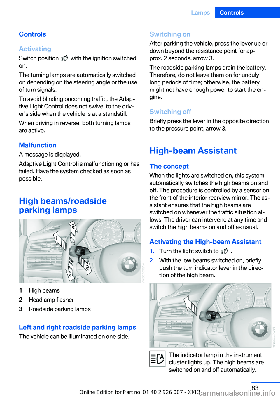
1High beams2Headlamp flasher3Roadside parking lamps
Left and right roadside parking lamps
The vehicle can be illuminated on one side.
Switching onAfter parking the vehicle, press the lever up ordown beyond the resistance point for ap‐
prox. 2 seconds, arrow 3.
The roadside parking lamps drain the battery.
Therefore, do not leave them on for unduly
long periods of time; otherwise, the battery
might not have enough power to start the en‐
gine.
Switching off
Briefly press the lever in the opposite direction
to the pressure point, arrow 3.
High-beam Assistant
The concept When the lights are switched on, this systemautomatically switches the high beams on and
off. The procedure is controlled by a sensor on
the front of the interior rearview mirror. The as‐
sistant ensures that the high beams are
switched on whenever the traffic situation al‐
lows. The driver can intervene at any time and
switch the high beams on and off as usual.
Activating the High-beam Assistant1.Turn the light switch to .2.With the low beams switched on, briefly
push the turn indicator lever in the direc‐
tion of the high beam.
The indicator lamp in the instrument
cluster lights up. The high beams are
switched on and off automatically.
Seite 83LampsControls83
Online Edition for Part no. 01 40 2 910 876 - VII/13
Page 88 of 327
The system responds to light from oncoming
traffic and traffic driving ahead of you, and to
adequate illumination, e.g., in towns and cities.
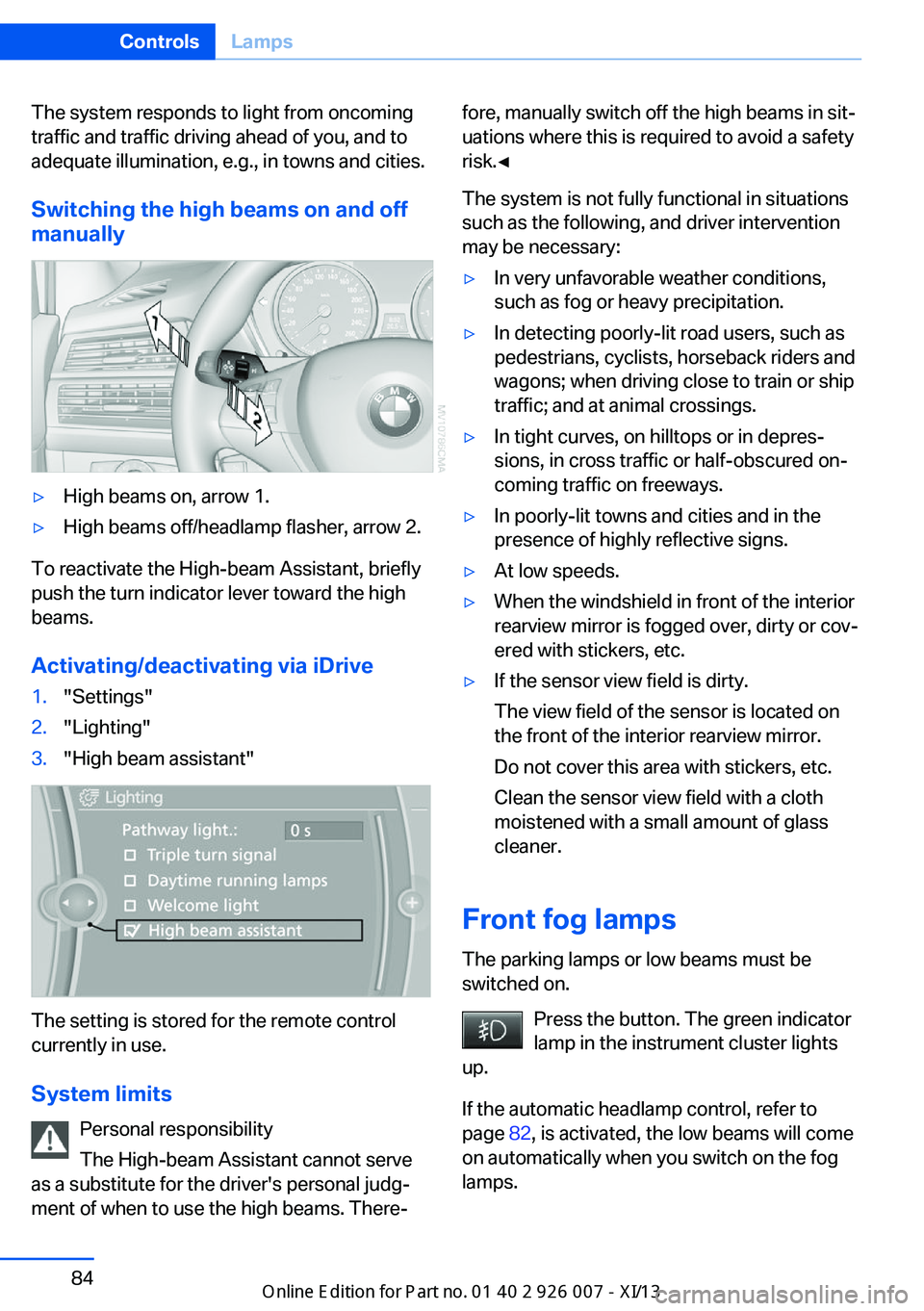
Switching the high beams on and offmanually▷High beams on, arrow 1.▷High beams off/headlamp flasher, arrow 2.
To reactivate the High-beam Assistant, briefly
push the turn indicator lever toward the high
beams.
Activating/deactivating via iDrive
1."Settings"2."Lighting"3."High beam assistant"
The setting is stored for the remote control
currently in use.
System limits Personal responsibility
The High-beam Assistant cannot serve
as a substitute for the driver's personal judg‐
ment of when to use the high beams. There‐
fore, manually switch off the high beams in sit‐
uations where this is required to avoid a safety
risk.◀
The system is not fully functional in situations
such as the following, and driver intervention
may be necessary:▷In very unfavorable weather conditions,
such as fog or heavy precipitation.▷In detecting poorly-lit road users, such as
pedestrians, cyclists, horseback riders and
wagons; when driving close to train or ship
traffic; and at animal crossings.▷In tight curves, on hilltops or in depres‐
sions, in cross traffic or half-obscured on‐
coming traffic on freeways.▷In poorly-lit towns and cities and in the
presence of highly reflective signs.▷At low speeds.▷When the windshield in front of the interior
rearview mirror is fogged over, dirty or cov‐
ered with stickers, etc.▷If the sensor view field is dirty.
The view field of the sensor is located on
the front of the interior rearview mirror.
Do not cover this area with stickers, etc.
Clean the sensor view field with a cloth
moistened with a small amount of glass
cleaner.
Front fog lamps
The parking lamps or low beams must be
switched on.
Press the button. The green indicator
lamp in the instrument cluster lights
up.
If the automatic headlamp control, refer to
page 82, is activated, the low beams will come
on automatically when you switch on the fog
lamps.
Seite 84ControlsLamps84
Online Edition for Part no. 01 40 2 910 876 - VII/13
Page 91 of 327
▷Make sure that the front passenger is sit‐
ting correctly, i.e., keeps his or her feet and
legs in the footwell; otherwise, leg injuries
can occur if the front airbag is triggered.▷Do not place slip covers, seat cushions or
other objects on the front passenger seat
that are not approved specifically for seats
with integrated side airbags.▷Do not hang pieces of clothing, such as
jackets, over the backrests.▷Make sure that occupants keep their heads
away from the side airbag and do not rest
against the head airbag; otherwise, injuries
can occur if the airbags are triggered.▷Do not remove the airbag restraint system.▷Do not remove the steering wheel.▷Do not apply adhesive materials to the air‐
bag cover panels, cover them or modify
them in any way.▷Never modify either the individual compo‐
nents or the wiring in the airbag system.
This also applies to steering wheel covers,
the dashboard, the seats, the roof pillars
and the sides of the headliner.◀
Even when all instructions are followed closely,
injury from contact with the airbags cannot be
ruled out in certain situations.
The ignition and inflation noise may lead to
short-term and, in most cases, temporary
hearing impairment in sensitive individuals.
In the case of a malfunction, deactivation
and after triggering of the airbags
Do not touch the individual components imme‐
diately after the system has been triggered;
otherwise, there is the danger of burns.
Only have the airbags checked, repaired or dis‐
mantled and the airbag generator scrapped by
your service center or a workshop that has the
necessary authorization for handling explo‐
sives.
Non-professional attempts to service the sys‐
tem could lead to failure in an emergency or
undesired triggering of the airbag, either of
which could result in injury.◀
Warnings and information on the airbags are
also found on the sun visors.
Automatic deactivation of the frontpassenger airbags
The occupation of the seat is detected by eval‐
uating the impression on the occupied seat
surface of the front passenger seat.
The front and side airbags on the front passen‐
ger side are activated or deactivated accord‐
ingly by the system.
The indicator lamp above the interior rearview
mirror shows the current status of the front
passenger airbags, deactivated or activated,
refer to Front passenger airbag indicator lamp
below.
Leave feet in the footwell
Make sure that the front passenger
keeps his or her feet in the footwell; otherwise,
the front passenger airbags may not function
properly.◀
Child restraint fixing system in the front
passenger seat
Before transporting a child on the front pas‐
senger seat, refer to the safety notes and in‐
structions under Children on the front passen‐
ger seat, refer to page 54.◀
Malfunction of the automatic
deactivation system
When transporting older children and adults,
the front passenger airbags may be deacti‐
vated in certain sitting positions. In this case,
the indicator lamp for the front passenger air‐ bags lights up.
In this case, change the sitting position so that
the front passenger airbags are activated and
the indicator lamp goes out.Seite 87SafetyControls87
Online Edition for Part no. 01 40 2 910 876 - VII/13
Page 98 of 327
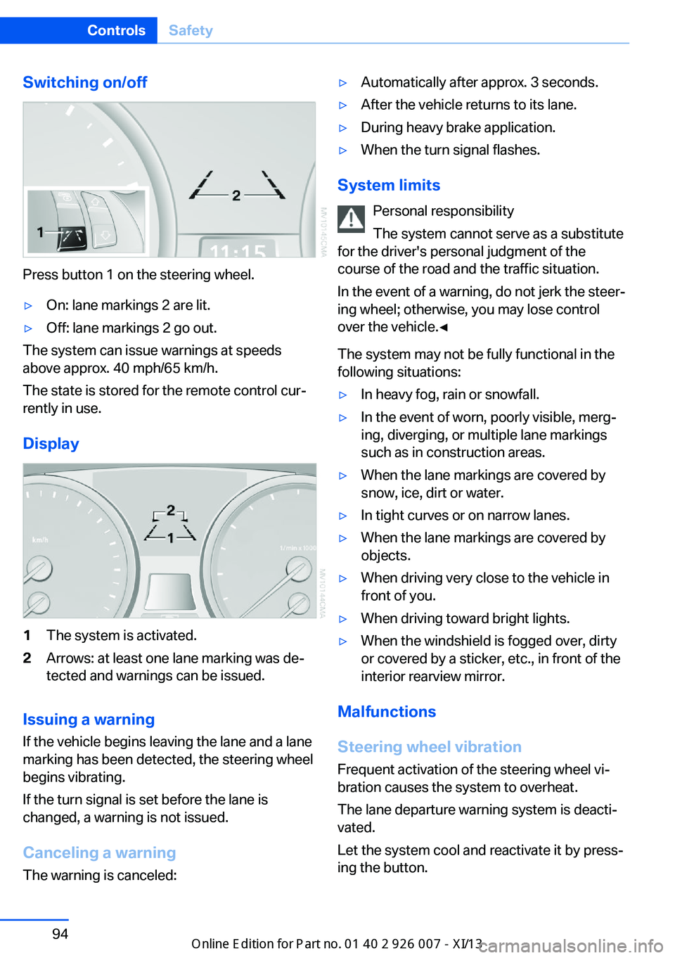
Switching on/off
Press button 1 on the steering wheel.
▷On: lane markings 2 are lit.▷Off: lane markings 2 go out.
The system can issue warnings at speeds
above approx. 40 mph/65 km/h.
The state is stored for the remote control cur‐
rently in use.
Display
1The system is activated.2Arrows: at least one lane marking was de‐
tected and warnings can be issued.
Issuing a warning
If the vehicle begins leaving the lane and a lane
marking has been detected, the steering wheel
begins vibrating.
If the turn signal is set before the lane is
changed, a warning is not issued.
Canceling a warning The warning is canceled:
▷Automatically after approx. 3 seconds.▷After the vehicle returns to its lane.▷During heavy brake application.▷When the turn signal flashes.
System limits
Personal responsibility
The system cannot serve as a substitute
for the driver's personal judgment of the
course of the road and the traffic situation.
In the event of a warning, do not jerk the steer‐
ing wheel; otherwise, you may lose control
over the vehicle.◀
The system may not be fully functional in the
following situations:
▷In heavy fog, rain or snowfall.▷In the event of worn, poorly visible, merg‐
ing, diverging, or multiple lane markings
such as in construction areas.▷When the lane markings are covered by
snow, ice, dirt or water.▷In tight curves or on narrow lanes.▷When the lane markings are covered by
objects.▷When driving very close to the vehicle in
front of you.▷When driving toward bright lights.▷When the windshield is fogged over, dirty
or covered by a sticker, etc., in front of the
interior rearview mirror.
Malfunctions
Steering wheel vibration
Frequent activation of the steering wheel vi‐
bration causes the system to overheat.
The lane departure warning system is deacti‐
vated.
Let the system cool and reactivate it by press‐
ing the button.
Seite 94ControlsSafety94
Online Edition for Part no. 01 40 2 910 876 - VII/13
Page 99 of 327
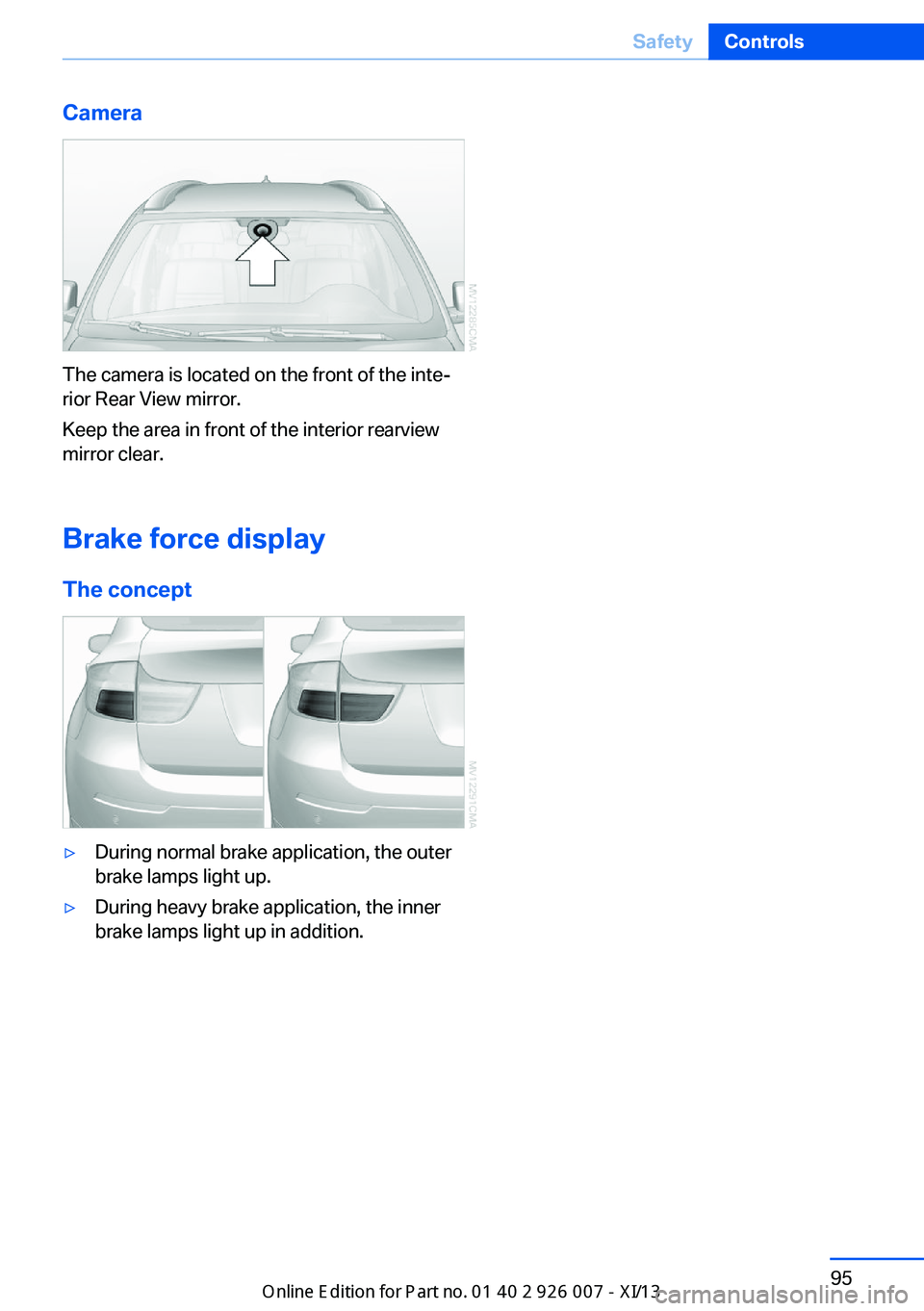
Camera
The camera is located on the front of the inte‐
rior Rear View mirror.
Keep the area in front of the interior rearview
mirror clear.
Brake force display The concept
▷During normal brake application, the outer
brake lamps light up.▷During heavy brake application, the inner
brake lamps light up in addition.Seite 95SafetyControls95
Online Edition for Part no. 01 40 2 910 876 - VII/13
Page 119 of 327
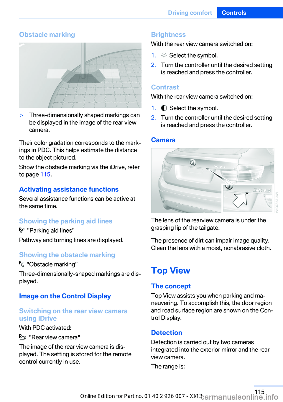
Obstacle marking▷Three-dimensionally shaped markings can
be displayed in the image of the rear view
camera.
Their color gradation corresponds to the mark‐
ings in PDC. This helps estimate the distance
to the object pictured.
Show the obstacle marking via the iDrive, refer
to page 115.
Activating assistance functions
Several assistance functions can be active at
the same time.
Showing the parking aid lines
"Parking aid lines"
Pathway and turning lines are displayed.
Showing the obstacle marking
"Obstacle marking"
Three-dimensionally-shaped markings are dis‐
played.
Image on the Control Display
Switching on the rear view camera
using iDrive
With PDC activated:
"Rear view camera"
The image of the rear view camera is dis‐
played. The setting is stored for the remote
control currently in use.
Brightness
With the rear view camera switched on:1. Select the symbol.2.Turn the controller until the desired setting
is reached and press the controller.
Contrast
With the rear view camera switched on:
1. Select the symbol.2.Turn the controller until the desired setting
is reached and press the controller.
Camera
The lens of the rearview camera is under the
grasping lip of the tailgate.
The presence of dirt can impair image quality.
Clean the lens with a moist, nonabrasive cloth.
Top View
The concept
Top View assists you when parking and ma‐
neuvering. To accomplish this, the door region
and road surface region are shown on the Con‐
trol Display.
Detection
Detection is carried out by two cameras
integrated into the exterior mirror and the rear
view camera.
The range is:
Seite 115Driving comfortControls115
Online Edition for Part no. 01 40 2 910 876 - VII/13
Page 120 of 327
▷Approx. 7 ft/2 m to the side.▷Approx. 7 ft/2 m to the rear.
Obstacles up to the height of the exterior mir‐
rors are thus detected in a timely fashion.
System limits
Top View cannot be used in the following sit‐
uations:
▷With a door open.▷With the tailgate open.▷With an exterior mirror folded in.▷In poor light.
The arrows next to the vehicle are displayed in
a shaded form on the Control Display and a
symbol appears at the corresponding location
on the vehicle.
Check the traffic situation as well
Check the traffic situation around the ve‐
hicle with your own eyes. Otherwise, an acci‐
dent could result from road users or objects lo‐
cated outside the picture area of the
cameras.◀
Switching on automatically
Select transmission position R with the engine
running.
The images from Top View and PDC are dis‐
played when the system has been switched on
using iDrive.
Switching off automatically when
driving forward
The system switches off when a certain dis‐
tance or speed is exceeded.
Switch on the system again if necessary.
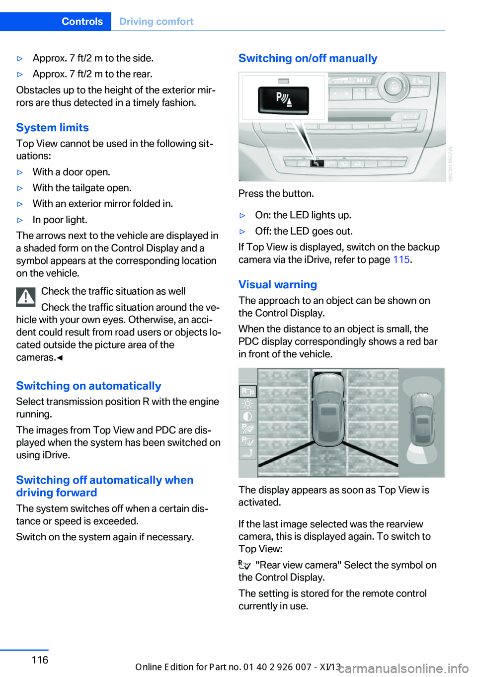
Switching on/off manually
Press the button.
▷On: the LED lights up.▷Off: the LED goes out.
If Top View is displayed, switch on the backup
camera via the iDrive, refer to page 115.
Visual warning
The approach to an object can be shown on
the Control Display.
When the distance to an object is small, the
PDC display correspondingly shows a red bar
in front of the vehicle.
The display appears as soon as Top View is
activated.
If the last image selected was the rearview
camera, this is displayed again. To switch to
Top View:
"Rear view camera" Select the symbol on
the Control Display.
The setting is stored for the remote control
currently in use.
Seite 116ControlsDriving comfort116
Online Edition for Part no. 01 40 2 910 876 - VII/13
Page 121 of 327
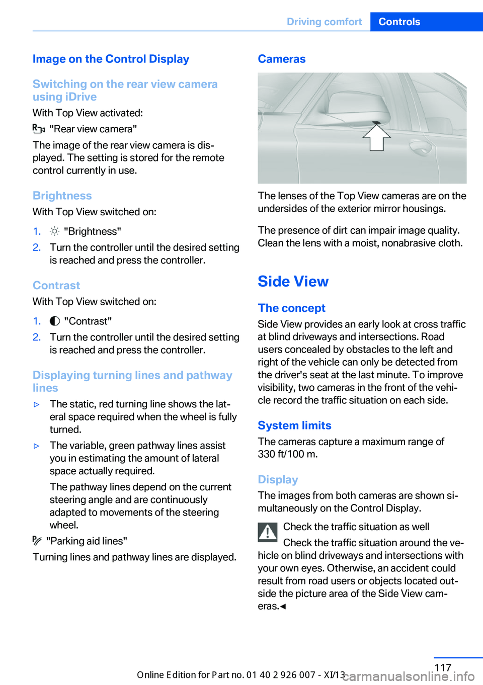
Image on the Control Display
Switching on the rear view camera
using iDrive
With Top View activated:
"Rear view camera"
The image of the rear view camera is dis‐
played. The setting is stored for the remote
control currently in use.
Brightness
With Top View switched on:
1. "Brightness"2.Turn the controller until the desired setting
is reached and press the controller.
Contrast
With Top View switched on:
1. "Contrast"2.Turn the controller until the desired setting
is reached and press the controller.
Displaying turning lines and pathway
lines
▷The static, red turning line shows the lat‐
eral space required when the wheel is fully
turned.▷The variable, green pathway lines assist
you in estimating the amount of lateral
space actually required.
The pathway lines depend on the current
steering angle and are continuously
adapted to movements of the steering
wheel.
"Parking aid lines"
Turning lines and pathway lines are displayed.
Cameras
The lenses of the Top View cameras are on the
undersides of the exterior mirror housings.
The presence of dirt can impair image quality.
Clean the lens with a moist, nonabrasive cloth.
Side ViewThe concept
Side View provides an early look at cross traffic
at blind driveways and intersections. Road
users concealed by obstacles to the left and
right of the vehicle can only be detected from
the driver's seat at the last minute. To improve
visibility, two cameras in the front of the vehi‐
cle record the traffic situation on each side.
System limits
The cameras capture a maximum range of
330 ft/100 m.
Display
The images from both cameras are shown si‐
multaneously on the Control Display.
Check the traffic situation as well
Check the traffic situation around the ve‐
hicle on blind driveways and intersections with
your own eyes. Otherwise, an accident could
result from road users or objects located out‐
side the picture area of the Side View cam‐
eras.◀
Seite 117Driving comfortControls117
Online Edition for Part no. 01 40 2 910 876 - VII/13
Page 133 of 327
Interior equipmentVehicle equipmentThis chapter describes all series equipment as
well as country-specific and special equipment
offered for this model series.Therefore, it also
describes equipment that may not be found in
your vehicle, for instance due to the selected
special equipment or the country version. This
also applies to safety-related functions and
systems.
Universal Garage Door
Opener
The concept The Universal Garage Door Opener can be
used to operate up to 3 functions in remote-
controlled systems, such as garage door drives or lighting systems. The Universal Garage
Door Opener replaces up to 3 different hand-
held transmitters. To operate it, the buttons on
the interior rearview mirror must be program‐
med for the desired functions. The hand-held
transmitter for the system is needed for the
programming procedure.
During programming
During programming and before activat‐
ing a device using the Universal Garage Door
Opener, ensure that there are no people, ani‐
mals, or objects in the range of movement of
the remote-controlled device; otherwise, there
is a risk of injury or damage.
Also follow the safety instructions of the hand-
held transmitter.◀
Before selling the vehicle, delete the stored
functions for security reasons.
Compatibility If this symbol is printed on the packag‐
ing or in the operating instructions ofthe system being operated, the system is gen‐
erally compatible with the Universal Garage
Door Opener.
If you have any questions, please contact:▷Your service center.▷www.homelink.com on the Internet.
HomeLink is a registered trademark of John‐
son Controls, Inc.
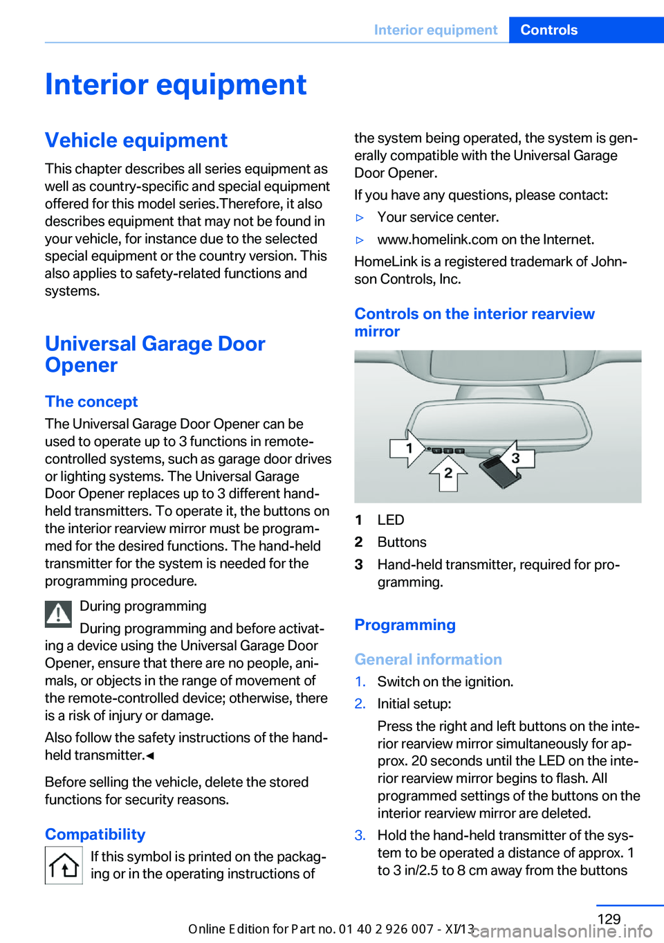
Controls on the interior rearview
mirror
1LED2Buttons3Hand-held transmitter, required for pro‐
gramming.
Programming
General information
1.Switch on the ignition.2.Initial setup:
Press the right and left buttons on the inte‐
rior rearview mirror simultaneously for ap‐
prox. 20 seconds until the LED on the inte‐
rior rearview mirror begins to flash. All
programmed settings of the buttons on the
interior rearview mirror are deleted.3.Hold the hand-held transmitter of the sys‐
tem to be operated a distance of approx. 1
to 3 in/2.5 to 8 cm away from the buttonsSeite 129Interior equipmentControls129
Online Edition for Part no. 01 40 2 910 876 - VII/13