steering BMW X6 2013 E71 Owner's Guide
[x] Cancel search | Manufacturer: BMW, Model Year: 2013, Model line: X6, Model: BMW X6 2013 E71Pages: 345, PDF Size: 9.45 MB
Page 105 of 345
Driving stability control systemsVehicle equipmentThis chapter describes all series equipment as
well as country-specific and special equipment
offered for this model series.Therefore, it also
describes equipment that may not be found in
your vehicle, for instance due to the selected
special equipment or the country version. This
also applies to safety-related functions and
systems.
Antilock Brake System ABS
ABS prevents locking of the wheels during
braking.
The vehicle remains steerable even during full
brake applications, thus increasing active
safety.
ABS is operational every time you start the en‐
gine.
CBC Cornering Brake
Control
When braking during curves or when braking
during a lane change, driving stability and
steering response are improved further.
Electronic brake-force
distribution
The system controls the brake pressure in the
rear wheels to ensure stable braking behavior.
Brake assistantWhen you apply the brakes rapidly, this system
automatically produces the maximum braking
force boost. It thus helps to achieve the short‐
est possible braking distance during full brak‐ing. This system utilizes all of the benefits pro‐
vided by ABS.
Do not reduce the pressure on the brake pedal
for the duration of the full braking.
Dynamic Stability Control DSC
The concept
DSC prevents traction loss in the driving
wheels when driving away and accelerating.
DSC also recognizes unstable vehicle condi‐
tions, such as fishtailing or nose-diving. Sub‐
ject to physical limits, DSC helps to keep the
vehicle on a steady course by reducing engine
speed and by applying brakes to the individual
wheels.
Adjust your driving style to the situation
An appropriate driving style is always the
responsibility of the driver.
The laws of physics cannot be repealed, even
with DSC.
Do not reduce the additional safety margin
with a risky driving style, as otherwise there is
a risk of an accident.◀
Deactivating DSC: DSC OFF
When DSC is deactivated, driving stability is
reduced during acceleration and when driving
in bends.
To increase vehicle stability, activate DSC
again as soon as possible.Seite 105Driving stability control systemsControls105
Online Edition for Part no. 01 40 2 918 395 - III/13
Page 107 of 345
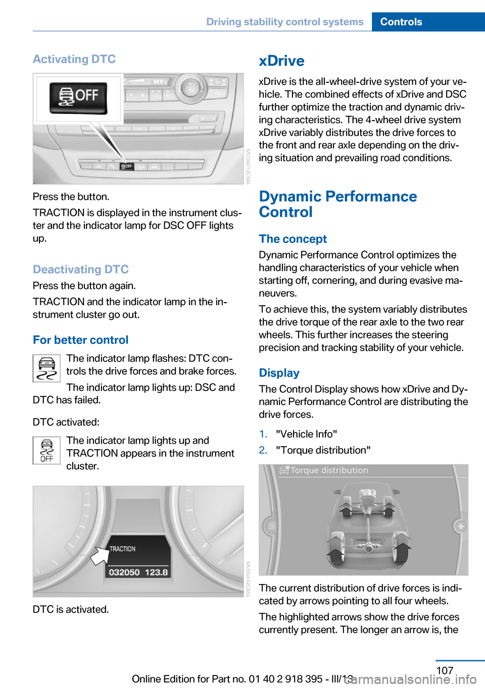
Activating DTC
Press the button.
TRACTION is displayed in the instrument clus‐
ter and the indicator lamp for DSC OFF lights
up.
Deactivating DTC
Press the button again.
TRACTION and the indicator lamp in the in‐
strument cluster go out.
For better control The indicator lamp flashes: DTC con‐
trols the drive forces and brake forces.
The indicator lamp lights up: DSC and
DTC has failed.
DTC activated: The indicator lamp lights up and
TRACTION appears in the instrument
cluster.
DTC is activated.
xDrive
xDrive is the all-wheel-drive system of your ve‐
hicle. The combined effects of xDrive and DSC
further optimize the traction and dynamic driv‐
ing characteristics. The 4-wheel drive system
xDrive variably distributes the drive forces to
the front and rear axle depending on the driv‐
ing situation and prevailing road conditions.
Dynamic Performance
Control
The concept Dynamic Performance Control optimizes the
handling characteristics of your vehicle when
starting off, cornering, and during evasive ma‐
neuvers.
To achieve this, the system variably distributes
the drive torque of the rear axle to the two rear
wheels. This further increases the steering
precision and tracking stability of your vehicle.
Display The Control Display shows how xDrive and Dy‐
namic Performance Control are distributing the
drive forces.1."Vehicle Info"2."Torque distribution"
The current distribution of drive forces is indi‐
cated by arrows pointing to all four wheels.
The highlighted arrows show the drive forces
currently present. The longer an arrow is, the
Seite 107Driving stability control systemsControls107
Online Edition for Part no. 01 40 2 918 395 - III/13
Page 109 of 345
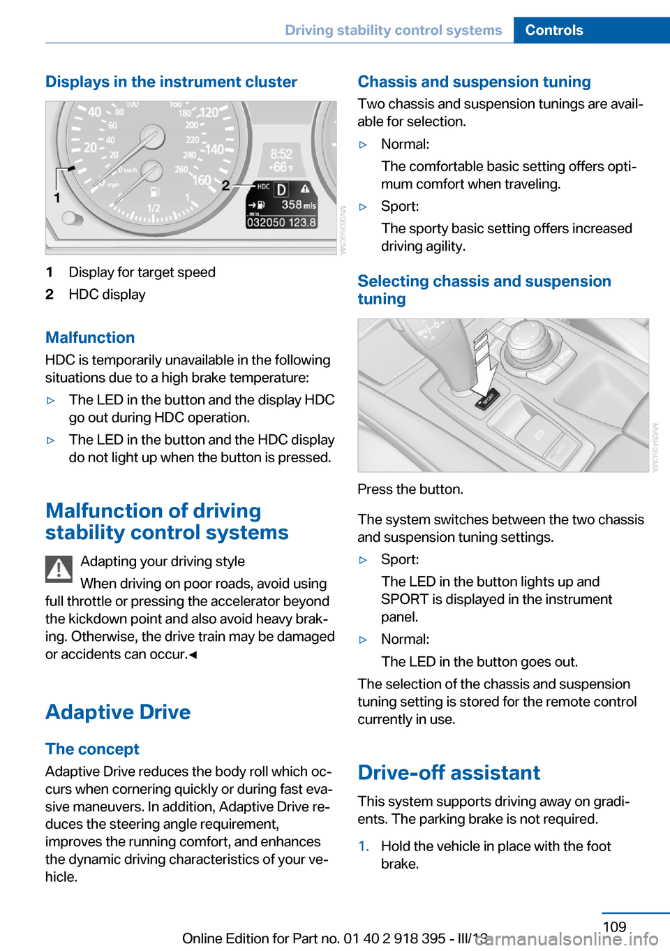
Displays in the instrument cluster1Display for target speed2HDC display
Malfunction
HDC is temporarily unavailable in the following
situations due to a high brake temperature:
▷The LED in the button and the display HDC
go out during HDC operation.▷The LED in the button and the HDC display
do not light up when the button is pressed.
Malfunction of driving
stability control systems
Adapting your driving style
When driving on poor roads, avoid using
full throttle or pressing the accelerator beyond
the kickdown point and also avoid heavy brak‐
ing. Otherwise, the drive train may be damaged
or accidents can occur.◀
Adaptive Drive The concept
Adaptive Drive reduces the body roll which oc‐
curs when cornering quickly or during fast eva‐
sive maneuvers. In addition, Adaptive Drive re‐
duces the steering angle requirement,
improves the running comfort, and enhances
the dynamic driving characteristics of your ve‐
hicle.
Chassis and suspension tuning
Two chassis and suspension tunings are avail‐
able for selection.▷Normal:
The comfortable basic setting offers opti‐
mum comfort when traveling.▷Sport:
The sporty basic setting offers increased
driving agility.
Selecting chassis and suspension
tuning
Press the button.
The system switches between the two chassis
and suspension tuning settings.
▷Sport:
The LED in the button lights up and
SPORT is displayed in the instrument
panel.▷Normal:
The LED in the button goes out.
The selection of the chassis and suspension
tuning setting is stored for the remote control
currently in use.
Drive-off assistant This system supports driving away on gradi‐
ents. The parking brake is not required.
1.Hold the vehicle in place with the foot
brake.Seite 109Driving stability control systemsControls109
Online Edition for Part no. 01 40 2 918 395 - III/13
Page 110 of 345
2.Release the foot brake and drive away
without delay.
Depending on the vehicle load, the vehicle may
roll back slightly.
Driving off without delay
After releasing the foot brake, start driv‐
ing without delay, since the drive-off assistant
will not hold the vehicle in place for more than
approx. 2 seconds and the vehicle will begin
rolling back.◀
Self-leveling suspension The concept The self-leveling suspension on the rear axle
assures a continuous ground clearance.
To do so, the height of the vehicle is measured
by sensors at both rear wheels.
If the actual height deviates from the defined
height, such as due to cargo in the vehicle, this
difference is compensated very quickly. In ad‐
dition, spring motions resulting from cornering
or irregularities in the road surface are reduced
to a minimum.
The system works automatically.
Malfunctions Malfunctions are displayed via Check Control,
refer to page 85.
Active steering The concept
The active steering actively varies the steering
angle of the front wheels in relation to the
steering wheel movements. In addition, it also
varies the steering force required for steering
depending on the vehicle's speed.
When you are driving in the low speed range,
for instance in a town or when parking, the
steering angle increases, i.e., steering be‐
comes very direct. In the higher speed range,
on the other hand, the steering angle is re‐
duced more and more. This improves the han‐
dling of your vehicle over the entire speed
range.
In critical situations, the system can make tar‐
geted corrections to the steering angle pro‐
vided by the driver and thus stabilize the vehi‐
cle before the driver intervenes.
Malfunction The warning lamp lights up yellow
and a message is shown on the Con‐
trol Display. The active steering is de‐
fective or has been temporarily deac‐
tivated. At low speeds, greater steering wheel
movements are required, whereas at higher
speeds, the vehicle reacts more sensitively to
steering wheel movements. The stability-pro‐
moting intervention can also be deactivated.
Proceed cautiously and drive defensively.
Deactivation
Active steering deactivates in order to carry
out an initialization. This deactivation is dis‐
played by means of a message. The initializa‐ tion can take several minutes.
If the message does not disappear during the
current trip, have the system checked.
Defect In the event of a defect, a corresponding text
message is displayed. Have the system
checked.Seite 110ControlsDriving stability control systems110
Online Edition for Part no. 01 40 2 918 395 - III/13
Page 118 of 345
system activated, resting your foot on the acel‐
erator pedal will cause the system not to brake
even if necessary. Be certain that floormats or
other objects on the vehicle floor do not inter‐
fere with movement of the acccelerator
pedal.◀
Limits of automatic braking
While active cruise control is capable of
braking your vehicle automatically when you
approach a slower vehicle ahead, it is impor‐
tant to be aware that the ability of the system
to apply the brakes is also limited, e.g. when
you reduce your desired speed sharply. lt uses
only a portion of braking system capacity and
does not utilize the full capacity of the vehicle
braking system. Therefore, the system cannot
decrease your speed for large differences in
speed between your vehicle and the vehicle
ahead. Examples: when you approach a vehicle
traveling at a much lower speed than your own
speed such as approaching a toll booth or
when a much slower vehicle cuts in front of
you at close range.◀
Cruise controlThe concept The system is functional at speeds beginning
at approx. 20 mph/30 km/h.
The speed specified using the lever on the
steering column is maintained.
The system brakes on downhill gradients if en‐
gine braking action is insufficient.
Do not use cruise control
Do not use the system if unfavorable
conditions make it impossible to drive at a con‐
stant speed, for instance:▷On curvy roads.▷In heavy traffic.▷On slippery roads, in fog, snow or rain, or
on a loose road surface.Otherwise, you could lose control of the vehi‐
cle and cause an accident.◀
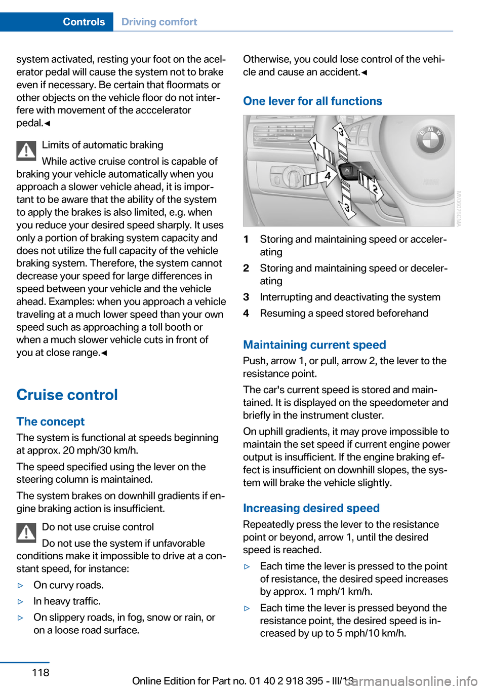
One lever for all functions1Storing and maintaining speed or acceler‐
ating2Storing and maintaining speed or deceler‐
ating3Interrupting and deactivating the system4Resuming a speed stored beforehand
Maintaining current speed
Push, arrow 1, or pull, arrow 2, the lever to the
resistance point.
The car's current speed is stored and main‐ tained. It is displayed on the speedometer and
briefly in the instrument cluster.
On uphill gradients, it may prove impossible to
maintain the set speed if current engine power
output is insufficient. If the engine braking ef‐
fect is insufficient on downhill slopes, the sys‐
tem will brake the vehicle slightly.
Increasing desired speed
Repeatedly press the lever to the resistance
point or beyond, arrow 1, until the desired
speed is reached.
▷Each time the lever is pressed to the point
of resistance, the desired speed increases
by approx. 1 mph/1 km/h.▷Each time the lever is pressed beyond the
resistance point, the desired speed is in‐
creased by up to 5 mph/10 km/h.Seite 118ControlsDriving comfort118
Online Edition for Part no. 01 40 2 918 395 - III/13
Page 123 of 345
Assistance functions
Functional requirement▷Rear view camera is switched on.▷Tailgate is completely closed.
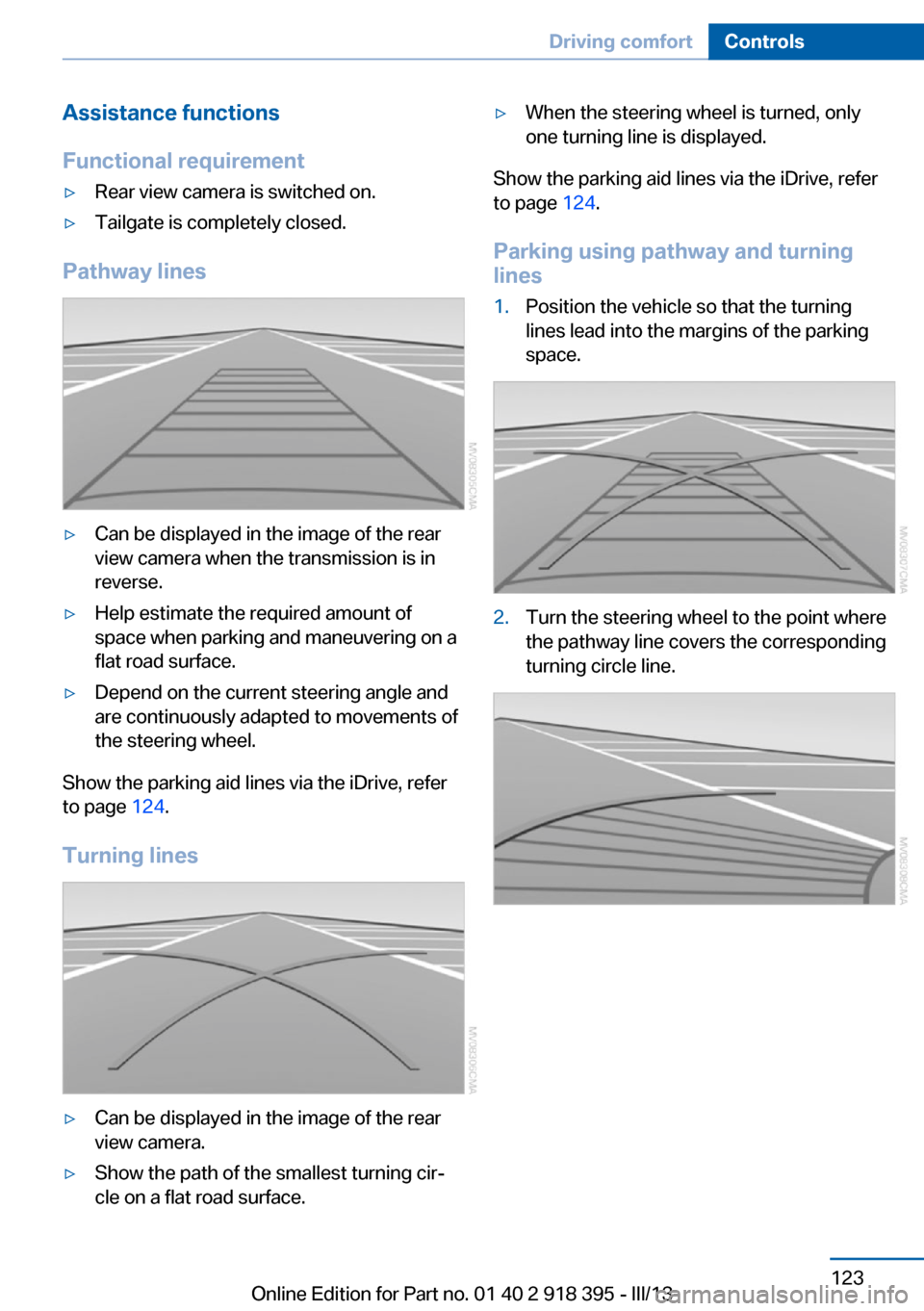
Pathway lines
▷Can be displayed in the image of the rear
view camera when the transmission is in
reverse.▷Help estimate the required amount of
space when parking and maneuvering on a
flat road surface.▷Depend on the current steering angle and
are continuously adapted to movements of
the steering wheel.
Show the parking aid lines via the iDrive, refer
to page 124.
Turning lines
▷Can be displayed in the image of the rear
view camera.▷Show the path of the smallest turning cir‐
cle on a flat road surface.▷When the steering wheel is turned, only
one turning line is displayed.
Show the parking aid lines via the iDrive, refer
to page 124.
Parking using pathway and turning
lines
1.Position the vehicle so that the turning
lines lead into the margins of the parking
space.2.Turn the steering wheel to the point where
the pathway line covers the corresponding
turning circle line.Seite 123Driving comfortControls123
Online Edition for Part no. 01 40 2 918 395 - III/13
Page 126 of 345
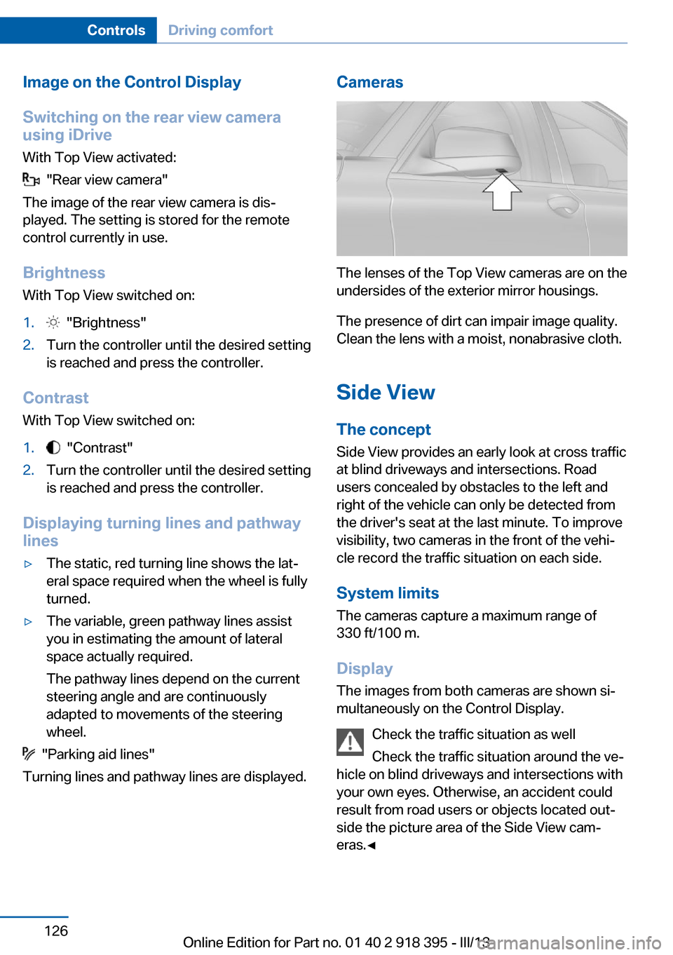
Image on the Control Display
Switching on the rear view camera
using iDrive
With Top View activated:
"Rear view camera"
The image of the rear view camera is dis‐
played. The setting is stored for the remote
control currently in use.
Brightness
With Top View switched on:
1. "Brightness"2.Turn the controller until the desired setting
is reached and press the controller.
Contrast
With Top View switched on:
1. "Contrast"2.Turn the controller until the desired setting
is reached and press the controller.
Displaying turning lines and pathway
lines
▷The static, red turning line shows the lat‐
eral space required when the wheel is fully
turned.▷The variable, green pathway lines assist
you in estimating the amount of lateral
space actually required.
The pathway lines depend on the current
steering angle and are continuously
adapted to movements of the steering
wheel.
"Parking aid lines"
Turning lines and pathway lines are displayed.
Cameras
The lenses of the Top View cameras are on the
undersides of the exterior mirror housings.
The presence of dirt can impair image quality.
Clean the lens with a moist, nonabrasive cloth.
Side ViewThe concept
Side View provides an early look at cross traffic
at blind driveways and intersections. Road
users concealed by obstacles to the left and
right of the vehicle can only be detected from
the driver's seat at the last minute. To improve
visibility, two cameras in the front of the vehi‐
cle record the traffic situation on each side.
System limits
The cameras capture a maximum range of
330 ft/100 m.
Display
The images from both cameras are shown si‐
multaneously on the Control Display.
Check the traffic situation as well
Check the traffic situation around the ve‐
hicle on blind driveways and intersections with
your own eyes. Otherwise, an accident could
result from road users or objects located out‐
side the picture area of the Side View cam‐
eras.◀
Seite 126ControlsDriving comfort126
Online Edition for Part no. 01 40 2 918 395 - III/13
Page 141 of 345
was aborted by the hand-held transmitter,
hold down the memory button and press
and release the button on the hand-held
transmitter several times for 2 seconds.
Controls
Prior to operation
Before operating a unit with the Universal
Garage Door Opener, ensure that there are no
people, animals, or objects in the range of
movement of the system; otherwise, there is a
risk of injury or damage.
Also follow the safety instructions of the hand-
held transmitter.◀
The system, such as the garage door, can be
operated using the button on the interior rear‐
view mirror with the engine running or the igni‐
tion switched on. When you are within the re‐
ception range of the system, press and hold
the button until the function is initiated. The
LED on the interior rearview mirror lights up
continuously while the radio signal is being
transmitted.
Deleting stored functions Press the right and left buttons on the interior
rearview mirror simultaneously for approx.
20 seconds until the LED flashes rapidly. All
stored functions are deleted. The functions
cannot be deleted individually.
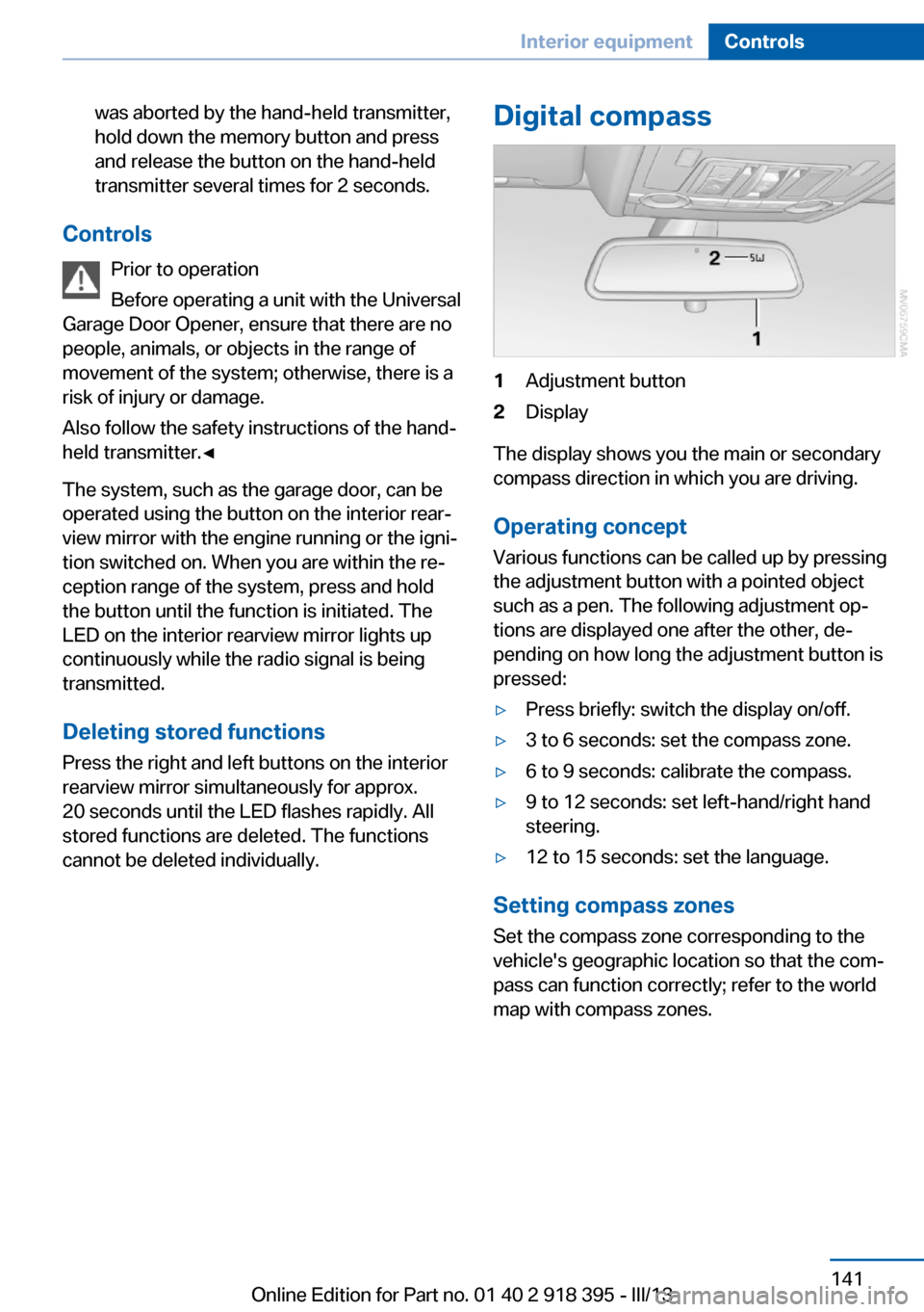
Digital compass1Adjustment button2Display
The display shows you the main or secondary
compass direction in which you are driving.
Operating concept
Various functions can be called up by pressing
the adjustment button with a pointed object
such as a pen. The following adjustment op‐
tions are displayed one after the other, de‐
pending on how long the adjustment button is
pressed:
▷Press briefly: switch the display on/off.▷3 to 6 seconds: set the compass zone.▷6 to 9 seconds: calibrate the compass.▷9 to 12 seconds: set left-hand/right hand
steering.▷12 to 15 seconds: set the language.
Setting compass zones
Set the compass zone corresponding to the
vehicle's geographic location so that the com‐
pass can function correctly; refer to the world
map with compass zones.
Seite 141Interior equipmentControls141
Online Edition for Part no. 01 40 2 918 395 - III/13
Page 142 of 345
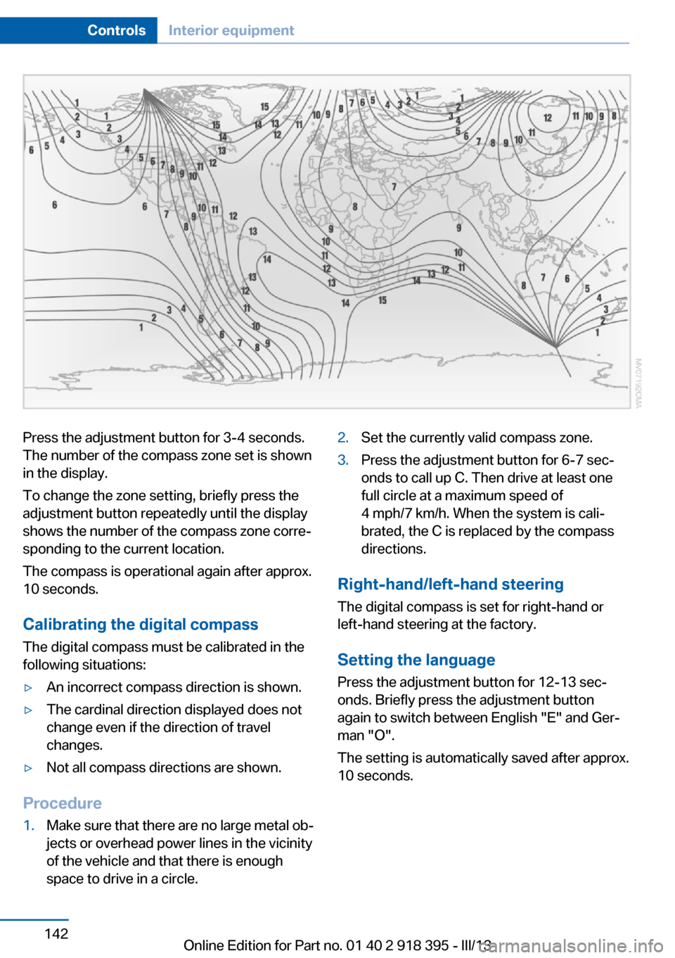
Press the adjustment button for 3‑4 seconds.
The number of the compass zone set is shown
in the display.
To change the zone setting, briefly press the
adjustment button repeatedly until the display
shows the number of the compass zone corre‐
sponding to the current location.
The compass is operational again after approx.
10 seconds.
Calibrating the digital compass
The digital compass must be calibrated in the
following situations:▷An incorrect compass direction is shown.▷The cardinal direction displayed does not
change even if the direction of travel
changes.▷Not all compass directions are shown.
Procedure
1.Make sure that there are no large metal ob‐
jects or overhead power lines in the vicinity
of the vehicle and that there is enough
space to drive in a circle.2.Set the currently valid compass zone.3.Press the adjustment button for 6‑7 sec‐
onds to call up C. Then drive at least one
full circle at a maximum speed of
4 mph/7 km/h. When the system is cali‐
brated, the C is replaced by the compass
directions.
Right-hand/left-hand steering
The digital compass is set for right-hand or
left-hand steering at the factory.
Setting the language Press the adjustment button for 12‑13 sec‐
onds. Briefly press the adjustment button
again to switch between English "E" and Ger‐
man "O".
The setting is automatically saved after approx.
10 seconds.
Seite 142ControlsInterior equipment142
Online Edition for Part no. 01 40 2 918 395 - III/13
Page 157 of 345
Hot exhaust systemHot exhaust system
High temperatures are generated in the
exhaust system.
Do not remove the heat shields installed and
never apply undercoating to them. Make sure
that flammable materials, e. g. hay, leaves,
grass, etc. do not come in contact with the hot
exhaust system during driving, while in idle po‐
sition mode, or when parked. Such contact
could lead to a fire, and with it the risk of seri‐
ous personal injury as well as property dam‐
age.
Do not touch hot exhaust pipes; otherwise,
there is the danger of getting burned.◀
Diesel particulate filter Soot particles are collected in the diesel partic‐
ulate filter and periodically burned away at high
temperatures.
The following may occur during the cleaning
period, which lasts several minutes:▷The engine temporarily runs somewhat
more roughly.▷A slightly higher engine speed is necessary
to achieve the accustomed performance.▷Noises occur and a minimal amount of
smoke emerges from the exhaust until
shortly after the engine is switched off.
Mobile communication devices in the
vehicle
Mobile communication devices in the ve‐
hicle
It is not recommended to use mobile phones,
such as mobile phones without a direct con‐
nection to an external aerial in the vehicle's
passenger compartment. Otherwise, the vehi‐
cle electronics and mobile communication de‐
vices can interfere with each other. In addition,
there is no assurance that the radiation gener‐
ated during transmission will be discharged
from the vehicle interior.◀
Hydroplaning
On wet or slushy roads, a wedge of water can
form between the tires and road surface.
This phenomenon is referred to as hydroplan‐
ing. It is characterized by a partial or complete
loss of contact between the tires and the road
surface, ultimately undermining your ability to
steer and brake the vehicle.
Hydroplaning
When driving on wet or slushy roads, re‐
duce your speed to prevent hydroplaning.◀
The risk of hydroplaning increases as the tire
tread depth decreases. Minimum tread depth,
refer to page 284.
Driving through water
Maximum water depth:▷BMW X5: 20 inches/50 cm.▷BMW X6: 17 inches/45 cm.
Adhere to water depth and speed limita‐
tions
Do not exceed this water depth and walking
speed; otherwise, the vehicle's engine, the
electrical systems and the transmission may
be damaged.◀
Braking safely
Your vehicle is equipped with ABS as a stand‐ ard feature.
Applying the brakes fully is the most effective
way of braking in situations when this is neces‐
sary.
The vehicle maintains steering responsive‐
ness. You can still avoid any obstacles with a
minimum of steering effort.
Pulsation of the brake pedal and sounds from
the hydraulic circuits indicate that ABS is in its
active mode.
Seite 157Things to remember when drivingDriving tips157
Online Edition for Part no. 01 40 2 918 395 - III/13