change time BMW X6 2016 F16 User Guide
[x] Cancel search | Manufacturer: BMW, Model Year: 2016, Model line: X6, Model: BMW X6 2016 F16Pages: 265, PDF Size: 6.17 MB
Page 137 of 265
Displaying distribution of the drive
torque1."Vehicle info"2."xDrive status"3. "Torque distribution"
HDC Hill Descent Control
The concept HDC is a downhill driving assistant that auto‐
matically controls vehicle speed on steep
downhill gradients. Without applying the
brakes, the vehicle moves at slightly more than
walking speed.
Hill Descent Control can be activated at
speeds below approx. 22 mph/35 km/h. When
driving downhill, the vehicle reduces its speed
to approx. walking speed and then keeps its
speed constant.
As long as there is active braking, the system
is on standby. The system does not brake the
vehicle during this time.
Only use HDC in low gears or in selector lever
position D or R.
Increasing or decreasing vehicle
speed
Specify desired speed in the range from ap‐
prox. 4 mph/6 km/h to approx. 15 mph/25 km/h
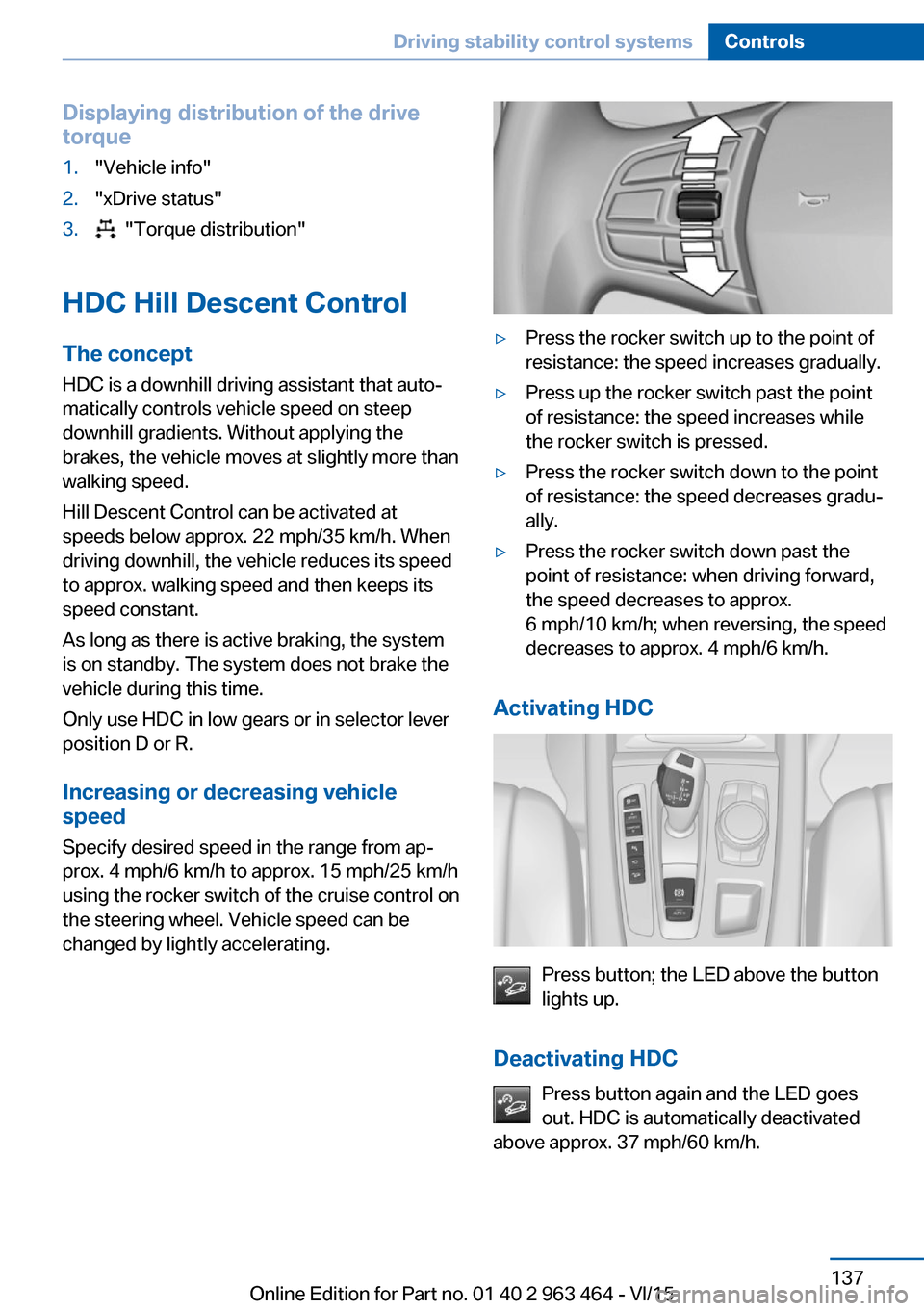
using the rocker switch of the cruise control on
the steering wheel. Vehicle speed can be
changed by lightly accelerating.
▷Press the rocker switch up to the point of
resistance: the speed increases gradually.▷Press up the rocker switch past the point
of resistance: the speed increases while
the rocker switch is pressed.▷Press the rocker switch down to the point
of resistance: the speed decreases gradu‐
ally.▷Press the rocker switch down past the
point of resistance: when driving forward,
the speed decreases to approx.
6 mph/10 km/h; when reversing, the speed
decreases to approx. 4 mph/6 km/h.
Activating HDC
Press button; the LED above the button
lights up.
Deactivating HDC Press button again and the LED goes
out. HDC is automatically deactivated
above approx. 37 mph/60 km/h.
Seite 137Driving stability control systemsControls137
Online Edition for Part no. 01 40 2 963 464 - VI/15
Page 143 of 265
Overview
Buttons on the steering wheelPress but‐
tonFunctionCruise control on/off, interrupt,
refer to page 143Store/maintain speed, refer to
page 144Resume speed, refer to
page 145Reduce distance, refer to
page 145Increase distance, refer to
page 145Rocker switch:
Maintain, store, change speed,
refer to page 144
Buttons are arranged according to vehicle's
series, optional features and country specifica‐
tions.
Radar sensor
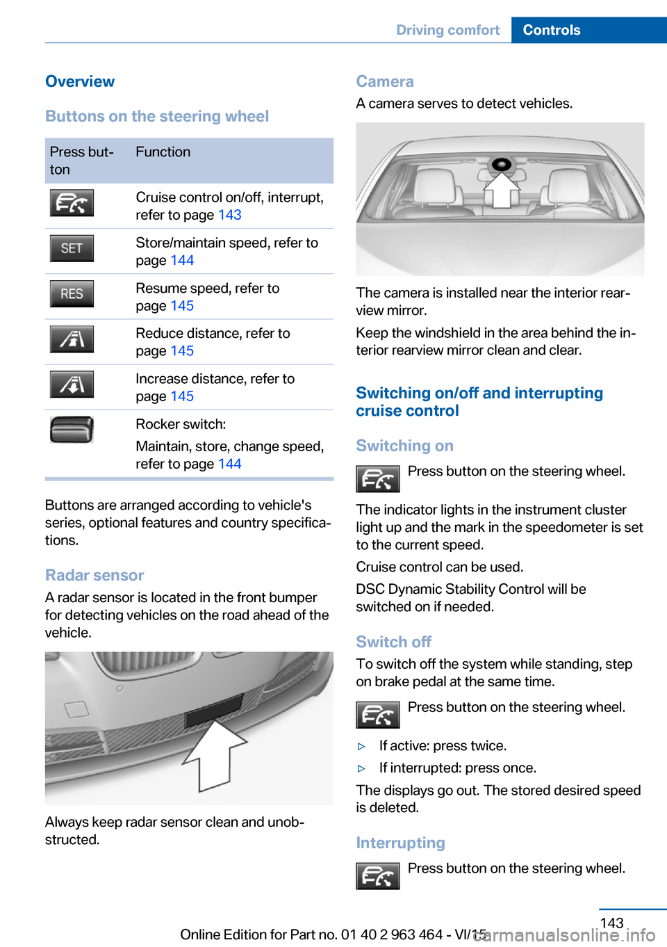
A radar sensor is located in the front bumper for detecting vehicles on the road ahead of the
vehicle.
Always keep radar sensor clean and unob‐
structed.
Camera
A camera serves to detect vehicles.
The camera is installed near the interior rear‐
view mirror.
Keep the windshield in the area behind the in‐
terior rearview mirror clean and clear.
Switching on/off and interrupting
cruise control
Switching on Press button on the steering wheel.
The indicator lights in the instrument cluster
light up and the mark in the speedometer is set
to the current speed.
Cruise control can be used.
DSC Dynamic Stability Control will be
switched on if needed.
Switch off To switch off the system while standing, step
on brake pedal at the same time.
Press button on the steering wheel.
▷If active: press twice.▷If interrupted: press once.
The displays go out. The stored desired speed
is deleted.
Interrupting Press button on the steering wheel.
Seite 143Driving comfortControls143
Online Edition for Part no. 01 40 2 963 464 - VI/15
Page 167 of 265
Switching on1.Switch off the ignition.2. Press the right side of the button
on the driver's side.
The symbol appears on the automatic cli‐
mate Control Display.
The interior temperature, air volume and air
distribution can be adjusted with the ignition
switched on.
Switch off
At the lowest fan speed, press the left side of
the button on the driver's side.
The symbol on the display of the automatic
climate control flashes.
Defrosts windows and removes
condensation
Press button.
Ice and condensation are quickly re‐
moved from the windshield and the front side
windows.
For this purpose, point the side vents onto the
side windows as needed.
Adjust air flow with the program active.
If the windows are fogged over, you can also
switch on the cooling function or press the AUTO button to utilize the condensation sen‐
sor.
Rear window defroster Press button.
The rear window defroster switches
off automatically after a certain period of time.
Microfilter/activated-charcoal filter
The microfilter removes dust and pollen from
the incoming air.
The activated-charcoal filter removes gaseous
pollutants from the outside air that enters the
vehicle.
This combined filter should be replaced during
scheduled maintenance, refer to page 228, of
your vehicle.
Ventilation
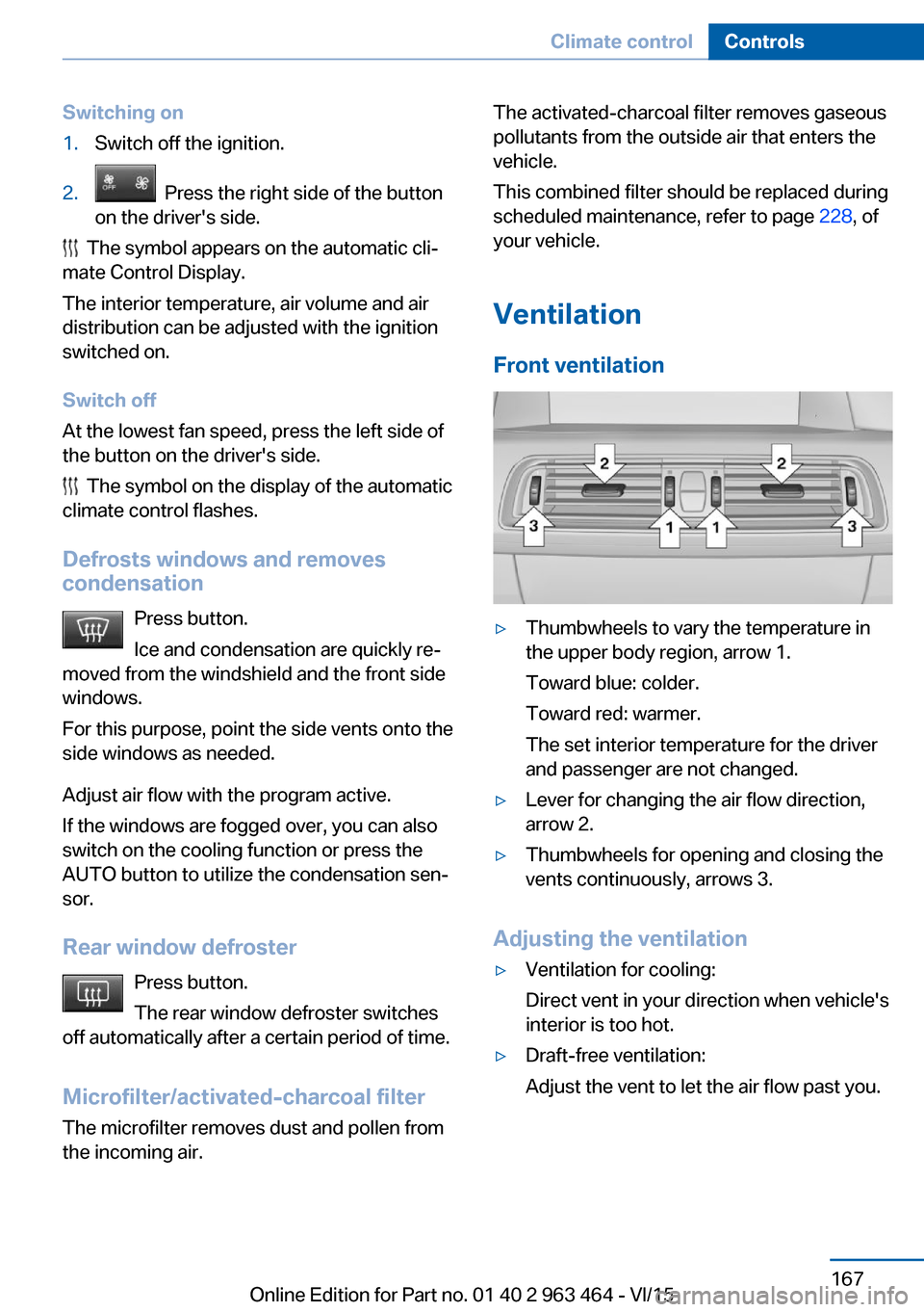
Front ventilation▷Thumbwheels to vary the temperature in
the upper body region, arrow 1.
Toward blue: colder.
Toward red: warmer.
The set interior temperature for the driver
and passenger are not changed.▷Lever for changing the air flow direction,
arrow 2.▷Thumbwheels for opening and closing the
vents continuously, arrows 3.
Adjusting the ventilation
▷Ventilation for cooling:
Direct vent in your direction when vehicle's
interior is too hot.▷Draft-free ventilation:
Adjust the vent to let the air flow past you.Seite 167Climate controlControls167
Online Edition for Part no. 01 40 2 963 464 - VI/15
Page 169 of 265
Air flows out of the vents to the upper body re‐
gion. The vents need to be open for this.
Air is cooled as quickly as possible:▷At an external temperature of approx.
32 ℉/0 ℃.▷When the engine is running.
AUTO program
Press button.
Air flow, air distribution, and tempera‐
ture are controlled automatically:
Depending on the selected temperature, the
AUTO intensity, and outside influences, the air
is directed to the upper body and into the foot‐
well.
The cooling function is switched on automati‐
cally with the AUTO program.
Intensity of the AUTO programWith the AUTO program activated, the auto‐
matic intensity control can be changed:
Press the left or right side of the but‐
ton: decrease or increase the inten‐
sity.
The selected intensity is shown on the display
of the automatic climate control.
Air flow, manual
To manually adjust air flow turn off AUTO pro‐
gram first.
Press the left or right side of the but‐
ton: decrease or increase air flow.
The selected air flow is shown on the display of
the automatic climate control.
Manual air distribution
The air distribution can be adjusted to individ‐
ual needs.
Press button repeatedly to select a
program:
▷Upper body region.▷Upper body region and footwell.▷Footwell.
Parked-car ventilation
The concept The parked-car ventilation ventilates the vehi‐
cle interior and lowers its temperature, if
needed.
The system can be switched on and off di‐
rectly or by using two preset departure times.
The reel-on time is automatically determined
based on the temperature. The system
promptly switches on before the selected de‐
parture time.
Operation can be performed via iDrive.
Functional requirements
Parked-car ventilation
▷When the departure time is preselected:
depends on internal, external and set tem‐
perature.▷Direct operation: any external temperature.
Open the vents to allow air to flow out.
Switching on/off directly
On the Control Display:
1."Settings"2."Climate"3."Activate now"
The symbol on the automatic climate con‐
trol flashes if the system is switched on.
The system continues to run for some time af‐
ter being switched off.
Seite 169Climate controlControls169
Online Edition for Part no. 01 40 2 963 464 - VI/15
Page 172 of 265
erases all programming of the buttons on
the interior rearview mirror.3.Hold the hand-held transmitter for the sys‐
tem to be controlled approx. 1 to 3 in/2.5 to
8 cm away from the buttons of the interior
rearview mirror. The required distance de‐
pends on the manual transmitter.4.Simultaneously press and hold the button
of the desired function on the hand-held
transmitter and the button to be program‐
med on the interior rearview mirror. The
LED on the interior rearview mirror will be‐
gin flashing slowly.5.Release both buttons as soon as the LED
flashes more rapidly. The LED flashing
faster indicates that the button on the inte‐
rior rearview mirror has been programmed.
If the LED does not flash faster after at
least 60 seconds, change the distance be‐
tween the interior rearview mirror and the
hand-held transmitter and repeat the step.
Several more attempts at different distan‐
ces may be necessary. Wait at least
15 seconds between attempts.
Canada: if programming with the hand-
held transmitter was interrupted, hold
down the interior rearview mirror button
and repeatedly press and release the
hand-held transmitter button for 2 sec‐
onds.6.To program other functions on other but‐
tons, repeat steps 3 to 5.
The systems can be controlled using the inte‐
rior rearview mirror buttons.
Special feature of the alternating-
code wireless system
If you are unable to operate the system after
repeated programming, please check if the
system to be controlled features an alternat‐
ing-code system.
Read the system's operating manual, or press
the programmed button on the interior rear‐
view mirror longer. If the LED on the interior
rearview mirror starts flashing rapidly and then
stays lit constantly for 2 seconds, the system
features an alternating-code system. Flashing
and continuous illumination of the LED will re‐
peat for approximately 20 seconds.
For systems with an alternating-code system,
the universal garage door opener and the sys‐
tem also have to be synchronized.
Please read the operating manual to find out how to synchronize the system.
Synchronizing is easier with the aid of a sec‐
ond person.
To synchronize:1.Park the vehicle within range of the re‐
mote-controlled system.2.Program the relevant button on the interior
rearview mirror as described.3.Locate and press the synchronizing button
on the system being programmed. You
have approx. 30 seconds for the next step.4.Hold down the programmed button on the
interior rearview mirror for approximately
3 seconds and then release it. If necessary,
repeat this step up to three times in order
to finish synchronization. Once synchroni‐
zation is complete, the programmed func‐
tion will be carried out.
Reprogramming individual buttons
1.Switch on the ignition.2.Press and hold the interior rearview mirror
button to be programmed.3.As soon as the interior rearview mirror LED
starts flashing slowly, hold the hand-held
transmitter for the system to be controlled
approx. 1 to 3 in/2.5 to 8 cm away from the
buttons of the interior rearview mirror. The
required distance depends on the manual
transmitter.Seite 172ControlsInterior equipment172
Online Edition for Part no. 01 40 2 963 464 - VI/15
Page 197 of 265
Overview
The system includes the following
EfficientDynamics functions and displays:▷ECO PRO bonus range, refer to page 197.▷ECO PRO tips driving instruction, refer to
page 198▷ECO PRO climate control, refer to
page 197.▷ECO PRO coasting driving status, refer to
page 199.
Activate ECO PRO
Press button repeatedly until ECO
PRO is displayed in the instrument
cluster.
Configuring ECO PRO
Via the Driving Dynamics Control
1.Activate ECO PRO.2."Configure ECO PRO"3.Configure the program.
Via the iDrive
1."Settings"2."Driving mode"3."Configure ECO PRO"
Configure the program.
ECO PRO Tip
▷"Tip at:":
Adjust the ECO PRO speed.▷"ECO PRO speed warning":
The output is reduced once the set ECO
PRO speed is reached.
ECO PRO climate control
"ECO PRO climate control"
Climate control is set to be fuel-efficient.
By making a slight change to the set tempera‐
ture, or slowly adjusting the rate of heating or
cooling of the car's interior, fuel consumption
can be economized.
The mirror heating is made available when out‐
side temperatures are very cold.
ECO PRO potential Shows potential savings with the current set‐
tings in percentages.
Display in the instrument cluster
Display in the instrument display
When ECO PRO mode is activated, the display
switches to a special configuration.
Some of the displays may differ from the dis‐
play in the instrument cluster.
Blue bar segments symbolize the gained bo‐
nus range in stages.
In addition, the bonus range is highlighted in
blue in the total range display.
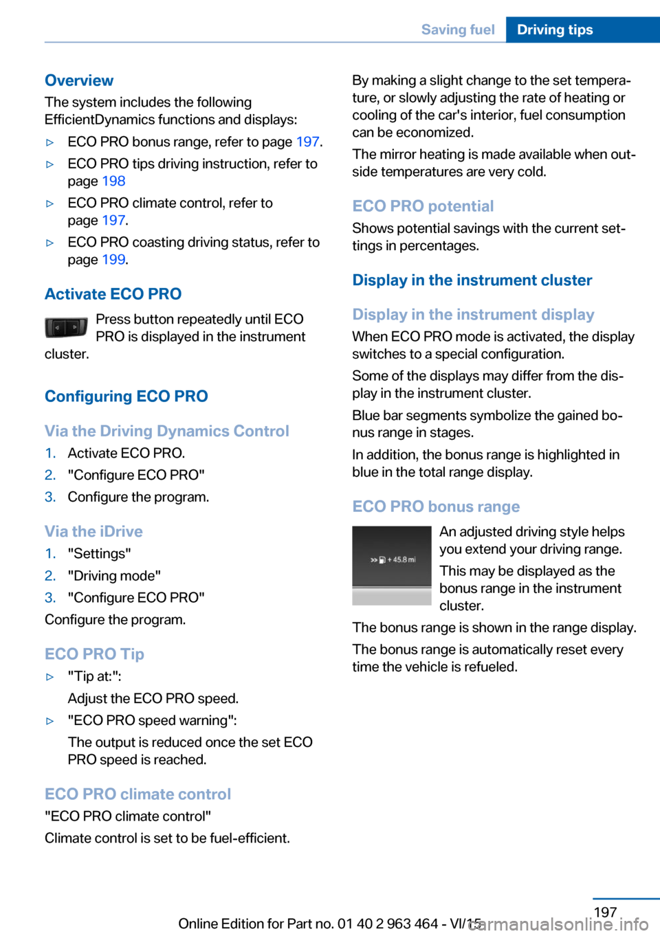
ECO PRO bonus range An adjusted driving style helps
you extend your driving range.
This may be displayed as the
bonus range in the instrument
cluster.
The bonus range is shown in the range display.
The bonus range is automatically reset every
time the vehicle is refueled.Seite 197Saving fuelDriving tips197
Online Edition for Part no. 01 40 2 963 464 - VI/15
Page 224 of 265
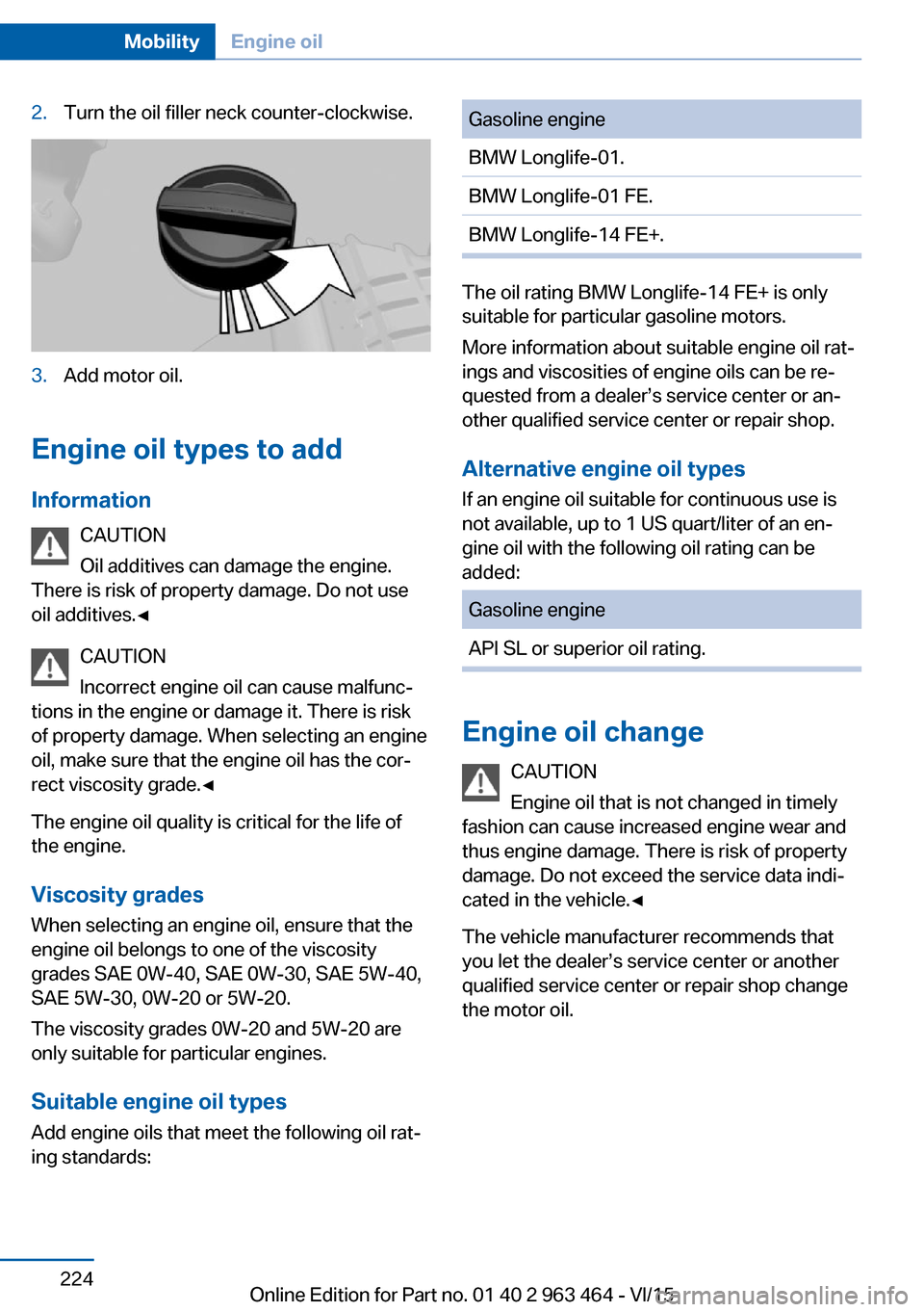
2.Turn the oil filler neck counter-clockwise.3.Add motor oil.
Engine oil types to addInformation CAUTION
Oil additives can damage the engine.
There is risk of property damage. Do not use
oil additives.◀
CAUTION
Incorrect engine oil can cause malfunc‐
tions in the engine or damage it. There is risk
of property damage. When selecting an engine oil, make sure that the engine oil has the cor‐
rect viscosity grade.◀
The engine oil quality is critical for the life of
the engine.
Viscosity gradesWhen selecting an engine oil, ensure that the
engine oil belongs to one of the viscosity
grades SAE 0W-40, SAE 0W-30, SAE 5W-40,
SAE 5W-30, 0W-20 or 5W-20.
The viscosity grades 0W-20 and 5W-20 are
only suitable for particular engines.
Suitable engine oil types Add engine oils that meet the following oil rat‐
ing standards:
Gasoline engineBMW Longlife-01.BMW Longlife-01 FE.BMW Longlife-14 FE+.
The oil rating BMW Longlife-14 FE+ is only
suitable for particular gasoline motors.
More information about suitable engine oil rat‐
ings and viscosities of engine oils can be re‐
quested from a dealer’s service center or an‐
other qualified service center or repair shop.
Alternative engine oil types If an engine oil suitable for continuous use is
not available, up to 1 US quart/liter of an en‐
gine oil with the following oil rating can be
added:
Gasoline engineAPI SL or superior oil rating.
Engine oil change
CAUTION
Engine oil that is not changed in timely
fashion can cause increased engine wear and
thus engine damage. There is risk of property
damage. Do not exceed the service data indi‐
cated in the vehicle.◀
The vehicle manufacturer recommends that
you let the dealer’s service center or another
qualified service center or repair shop change
the motor oil.
Seite 224MobilityEngine oil224
Online Edition for Part no. 01 40 2 963 464 - VI/15
Page 232 of 265
WARNING
Too intensive brightness can irritate or
damage the retina of the eye. There is risk of
injuries. Do not look directly into the headlights
or other light sources for an extended period of
time. Do not remove the LED covers.◀
Headlight glass
Condensation can form on the inside of the ex‐
ternal lights in cool or humid weather. When
driving with the lights switched on, the con‐
densation evaporates after a short time. The
headlight glass does not need to be changed.
If despite driving with the lights switched on,
increasing humidity forms, e. g. water droplets
in the lamp, the manufacturer of your vehicle
recommends having it checked by a dealer’s
service center or another qualified service cen‐
ter or repair shop.
Headlight setting
The headlight adjustments can be affected by
changing lights and bulbs. After the headlight
adjustment was changed, have it checked and,
if necessary, corrected by a dealer’s service
center or another qualified service center or re‐
pair shop.
Front lights, bulb replacement
Xenon headlights Information
Because of the long service life of these bulbs,
the likelihood of failure is very low. Switching
the lights on and off frequently shortens their
service life.
If a bulb fails, turn on the front fog lights and
continue the trip with great care. Comply with
local regulations.
DANGER
There can be high voltage in the lighting
system. There is danger to life. The manufac‐
turer of your vehicle recommends that thework on the lighting system including bulb re‐
placement be performed by a dealer’s service
center or another qualified service center or re‐
pair shop.◀
For checking and adjusting headlamp aim,
contact a dealer’s service center or another
qualified service center or repair shop.
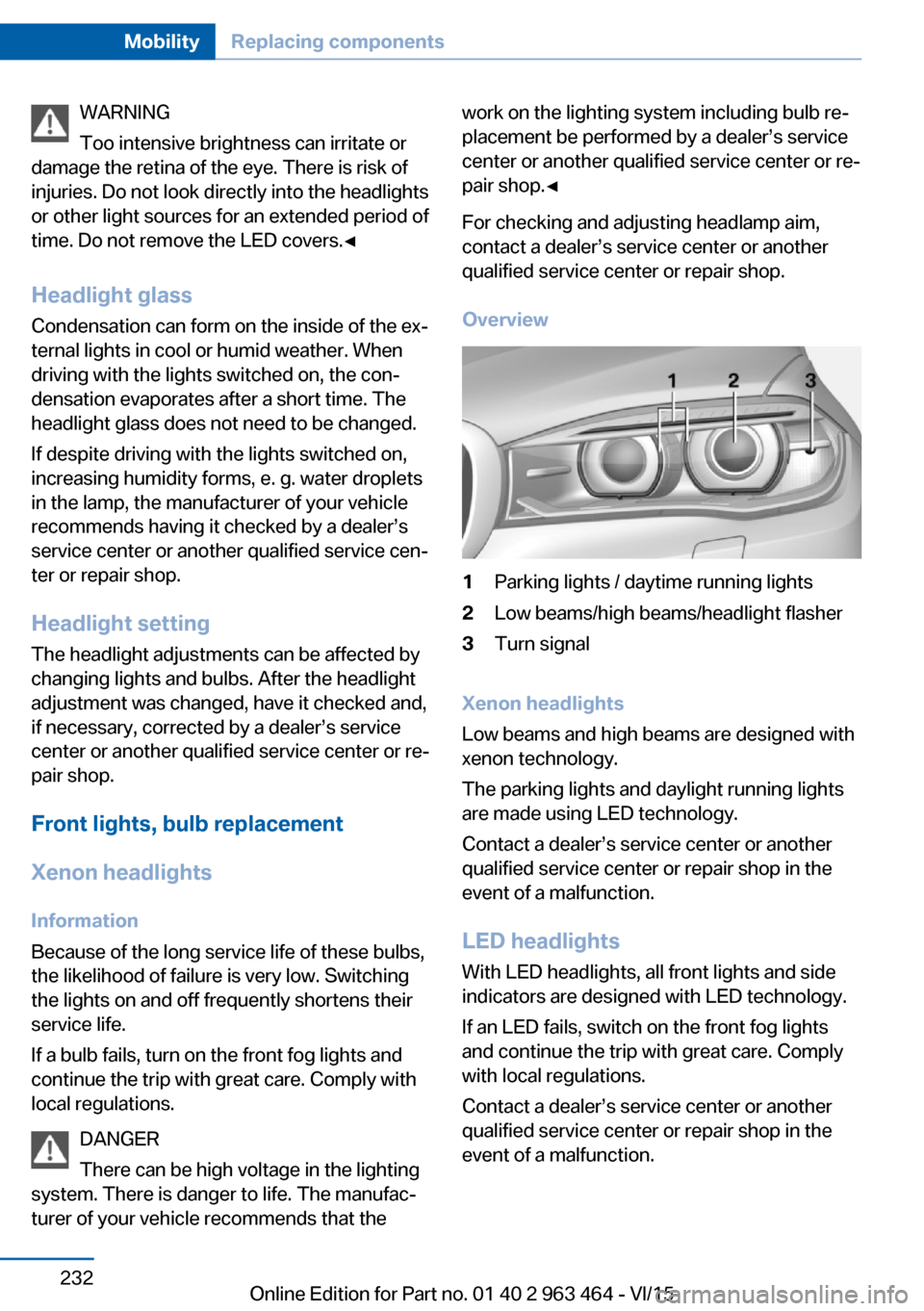
Overview1Parking lights / daytime running lights2Low beams/high beams/headlight flasher3Turn signal
Xenon headlights
Low beams and high beams are designed with
xenon technology.
The parking lights and daylight running lights
are made using LED technology.
Contact a dealer’s service center or another
qualified service center or repair shop in the
event of a malfunction.
LED headlights With LED headlights, all front lights and side
indicators are designed with LED technology.
If an LED fails, switch on the front fog lights and continue the trip with great care. Comply
with local regulations.
Contact a dealer’s service center or another
qualified service center or repair shop in the
event of a malfunction.
Seite 232MobilityReplacing components232
Online Edition for Part no. 01 40 2 963 464 - VI/15
Page 236 of 265
Reset the Tire Pressure Monitor.5.Check to make sure the lug bolts are tight
with a calibrated torque wrench.6.Replace the damaged tires as soon as pos‐
sible.
Driving with emergency wheel
WARNING
The emergency wheel has particular di‐
mensions. When driving with an emergency
wheel, changed driving properties may occur
at higher speeds, e.g. reduced lane stability
when braking, longer braking distance and
changed self-steering properties in the limit
area. There is risk of an accident. Drive moder‐
ately and do not exceed a speed of
50 mph/80 km/h.◀
Vehicle battery Maintenance
The battery is maintenance-free.
The added amount of acid is sufficient for the
service life of the battery.
More information about the battery can be re‐
quested from a dealer’s service center or an‐
other qualified service center or repair shop.
Battery replacement CAUTION
Vehicle batteries that are not compatible
can damage vehicle systems and impair vehi‐
cle functions.There is risk of property damage.
Information on the compatible vehicle batteries
is available at your dealer's service center.◀
After a battery replacement, the manufacturer
of your vehicle recommends that the vehicle
battery be registered on the vehicle by a
dealer’s service center or another qualified
service center or repair shop to ensure that all
comfort features are fully available and that any
Check Control messages of these comfort fea‐
tures are no longer displayed.
Charging the battery
General information
Make sure that the battery is always suffi‐
ciently charged to guarantee that the battery
remains usable for its full service life.
The battery may need to be charged in the fol‐
lowing cases:▷When making frequent short-distance
drives.▷If the vehicle is not used for prolonged pe‐
riods, longer than a month.
Information
CAUTION
Battery chargers for the vehicle battery
can work with high voltages and currents,
which means that the 12V on-board network
can be overloaded or damaged. There is risk of
property damage. Only connect battery charg‐
ers for the vehicle battery to the starting aid
terminals in the engine compartment.◀
Starting aid terminals
In the vehicle, only charge the battery via the
starting aid terminals, refer to page 240, in the
engine compartment with the engine off.
Power failure
After a temporary power loss, some equipment
needs to be newly initialized or individual set‐
tings updated, e. g.:
▷Seat, mirror, and steering wheel memory:
store the positions again.▷Time: update.▷Date: update.▷Glass sunroof: initialize the system, refer to
page 51.Seite 236MobilityReplacing components236
Online Edition for Part no. 01 40 2 963 464 - VI/15
Page 255 of 265
Blinds, sun protection 49
BMW Assist, see user's manual for Navigation, En‐
tertainment and Communi‐
cation
BMW Driver’s Guide App 6
BMW Homepage 6
BMW Internet page 6
BMW maintenance sys‐ tem 228
Bonus range, ECO PRO 197
Bottle holder, see Cu‐ pholder 183
Brake assistant 134
Brake assistant, adaptive 134
Brake discs, break-in 188
Brake force display 132
Brake lights, adaptive 132
Brake lights, brake force dis‐ play 132
Brake pads, break-in 188
Braking, hints 189
Breakdown assistance 238
Break-in 188
Brightness of Control Dis‐ play 98
Bulb replacement 231
Bulb replacement, front 232
Bulb replacement, rear 234
Bulbs and lights 231
Button, RES 145
Button, Start/Stop 67
Bypassing, see Jump-start‐ ing 239
C
California Proposition 65 Warning 8
Calling up mirror adjust‐ ment 46
Calling up seat adjust‐ ment 46
Calling up steering wheel ad‐ justment 46
Camera lenses, care 246 Camera, rearview cam‐
era 154
Camera, Side View 158
Camera, Top View 157
Can holder, see Cu‐ pholder 183
Car battery 236
Car care products 244
Care, displays 246
Care, vehicle 244
Cargo 192
Cargo area 178
Cargo area, enlarging 178
Cargo area, storage compart‐ ments 184
Cargo cover 178
Cargo, securing 193
Cargo straps, securing cargo 193
Car key, see Remote con‐ trol 34
Carpet, care 246
Car wash 243
Catalytic converter, see Hot exhaust system 189
CBS Condition Based Serv‐ ice 228
CD/Multimedia, see user's manual for Navigation, En‐
tertainment and Communi‐
cation
Center armrest 181
Center console 16
Central locking system 40
Central screen, see Control Display 18
Changes, technical, see Own Safety 7
Changing parts 230
Changing wheels 234
Changing wheels/tires 213
Chassis number, see vehicle identification number 10
Check Control 86
Checking the engine oil level electronically 222 Checking the oil level elec‐
tronically 222
Children, seating position 62
Children, transporting safely 62
Child restraint fixing sys‐ tem 62
Child restraint fixing system LATCH 64
Child restraint fixing systems, mounting 63
Child safety locks 65
Child seat, mounting 63
Child seats 62
Chrome parts, care 245
Cigarette lighter 174
Cleaning displays 246
Climate control 164
Climate control wind‐ shield 189
Clock 91
Closing/opening via door lock 39
Closing/opening with remote control 37
Closing the tailgate with no- touch activation 44
Clothes hooks 184
Coasting 199
Coasting with engine decou‐ pled, coasting 199
Coasting with idling en‐ gine 199
Cockpit 14
Combination switch, refer to Wiper system 75
Combination switch, see Turn signals 74
Comfort Access 42
COMFORT program, Driving Dynamics Control 140
Compact wheel, see Emer‐ gency wheel 234
Compartments in the doors 181
Compass 96 Seite 255Everything from A to ZReference255
Online Edition for Part no. 01 40 2 963 464 - VI/15