check engine BMW X6 2016 F16 User Guide
[x] Cancel search | Manufacturer: BMW, Model Year: 2016, Model line: X6, Model: BMW X6 2016 F16Pages: 265, PDF Size: 6.17 MB
Page 110 of 265
Status displayThe current status of the Tire Pressure Moni‐
tor TPM can be displayed on the Control Dis‐
play, e.g., whether or not the TPM is active.
On the Control Display:1."Vehicle info"2."Vehicle status"3. "Tire Pressure Monitor (TPM)"
The status is displayed.
Status control display Tire and system status are indicated by the
color of the wheels and a text message on the
Control Display.
All wheels green System is active and will issue a warning rela‐
tive to the tire inflation pressures stored during
the last reset.
One wheel is yellow A flat tire or major drop in inflation pressure in
the indicated tire.
All wheels are yellow A flat tire or major drop in inflation pressure in
several tires.
Wheels, gray The system cannot detect a flat tire. Reasons
for this may be:
▷The system is being reset.▷Malfunction.
Status information
The status control display additionally shows
the current tire inflation pressures and, de‐
pending on the model, tire temperatures. It
shows the actual values read; they may vary depending on driving style or weather condi‐
tions.
Carry out reset
Reset the system after each adjustment of the
tire inflation pressure and after every tire or
wheel change.
On the Control Display and on the vehicle:1."Vehicle info"2."Vehicle status"3. "Perform reset"4.Start the engine - do not drive off.5.Reset tire inflation pressure: "Perform
reset".6.Drive away.
The wheels are displayed in gray and the sta‐
tus is displayed.
After driving faster than 19 mph/30 km/h for a
short period, the set tire inflation pressures are
accepted as reference values. The reset is
completed automatically while driving.
The progress of the reset is displayed.
After a successfully completed Reset, the
wheels on the Control Display are shown in
green and "Tire Pressure Monitor (TPM)
active" is displayed.
You may interrupt this trip at any time. When
you continue the reset resumes automatically.
Low tire pressure message The yellow warning lamp lights up. A
Check Control message is displayed.
▷There is a flat tire or a major loss in
tire inflation pressure.▷No reset was performed for the system.
The system therefore issues a warning
based on the tire inflation pressures before
the last reset.1.Reduce your speed and stop cautiously.
Avoid sudden braking and steering maneu‐
vers.2.Check whether the vehicle is fitted with
normal tires or run-flat tires.Seite 110ControlsSafety110
Online Edition for Part no. 01 40 2 963 464 - VI/15
Page 113 of 265
the low tire pressure telltale illuminates, you
should stop and check your tires as soon as
possible, and inflate them to the proper pres‐
sure. Driving on a significantly under-inflated
tire causes the tire to overheat and can lead to
tire failure. Under-inflation also reduces fuel ef‐
ficiency and tire tread life, and may affect the
vehicle's handling and stopping ability. Please
note that the TPMS is not a substitute for
proper tire maintenance, and it is the driver's
responsibility to maintain correct tire pressure,
even if under-inflation has not reached the
level to trigger illumination of the TPMS low
tire pressure telltale. Your vehicle has also
been equipped with a TPMS malfunction indi‐
cator to indicate when the system is not oper‐
ating properly. The TPMS malfunction indica‐
tor is combined with the low tire pressure
telltale. When the system detects a malfunc‐
tion, the telltale will flash for approximately one
minute and then remain continuously illumi‐
nated. This sequence will continue upon sub‐
sequent vehicle start-ups as long as the mal‐
function exists. When the malfunction indicator
is illuminated, the system may not be able to
detect or signal low tire pressure as intended.
TPMS malfunctions may occur for a variety of
reasons, including the installation of replace‐
ment or alternate tires or wheels on the vehicle
that prevent the TPMS from functioning prop‐
erly. Always check the TPMS malfunction tell‐
tale after replacing one or more tires or wheels
on your vehicle to ensure that the replacement
or alternate tires and wheels allow the TPMS
to continue to function properly.
FTM Flat Tire Monitor The conceptThe system detects tire inflation pressure losson the basis of rotation speed differences be‐
tween the individual wheels while driving.
In the event of a tire inflation pressure loss, the
diameter and therefore the rotational speed ofthe corresponding wheel changes. This will be
detected and reported as a flat tire.
The system does not measure the actual infla‐
tion pressure in the tires.
Functional requirements
The system must have been initialized when
the tire inflation pressure was correct; other‐
wise, reliable flagging of a flat tire is not as‐
sured. Initialize the system after each correc‐ tion of the tire inflation pressure and after
every tire or wheel change.
Status display
The current status of the Flat Tire Monitor can
be displayed on the Control Display, e.g.,
whether or not the FTM is active.
On the Control Display:1."Vehicle info"2."Vehicle status"3. "Flat Tire Monitor (FTM)"
The status is displayed.
Initialization
When initializing the once set inflation tire
pressures serve as reference values in order to
detect a flat tire. Initialization is started by con‐
firming the tire inflation pressures.
Do not initialize the system when driving with
snow chains.
On the Control Display:
1."Vehicle info"2."Vehicle status"3. "Perform reset"4.Start the engine - do not drive off.5.Start the initialization with "Perform reset".6.Drive away.
The initialization is completed while driving,
which can be interrupted at any time.
The initialization automatically continues when
driving resumes.
Seite 113SafetyControls113
Online Edition for Part no. 01 40 2 963 464 - VI/15
Page 148 of 265
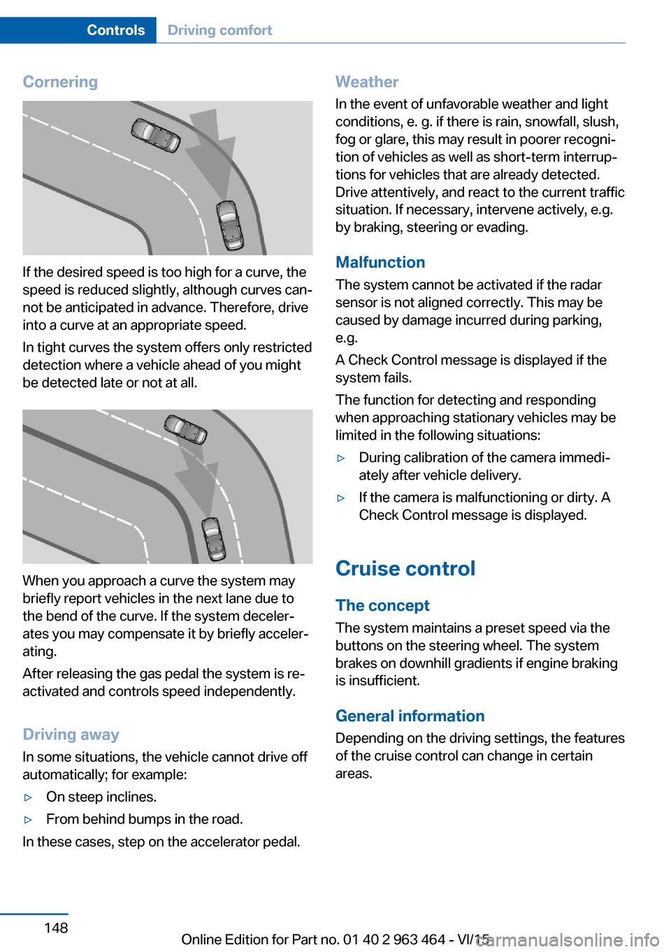
Cornering
If the desired speed is too high for a curve, the
speed is reduced slightly, although curves can‐
not be anticipated in advance. Therefore, drive
into a curve at an appropriate speed.
In tight curves the system offers only restricted
detection where a vehicle ahead of you might
be detected late or not at all.
When you approach a curve the system may
briefly report vehicles in the next lane due to
the bend of the curve. If the system deceler‐
ates you may compensate it by briefly acceler‐
ating.
After releasing the gas pedal the system is re‐
activated and controls speed independently.
Driving away In some situations, the vehicle cannot drive off
automatically; for example:
▷On steep inclines.▷From behind bumps in the road.
In these cases, step on the accelerator pedal.
Weather
In the event of unfavorable weather and light conditions, e. g. if there is rain, snowfall, slush,
fog or glare, this may result in poorer recogni‐
tion of vehicles as well as short-term interrup‐
tions for vehicles that are already detected. Drive attentively, and react to the current trafficsituation. If necessary, intervene actively, e.g.
by braking, steering or evading.
Malfunction
The system cannot be activated if the radar sensor is not aligned correctly. This may be
caused by damage incurred during parking,
e.g.
A Check Control message is displayed if the
system fails.
The function for detecting and responding
when approaching stationary vehicles may be limited in the following situations:▷During calibration of the camera immedi‐
ately after vehicle delivery.▷If the camera is malfunctioning or dirty. A
Check Control message is displayed.
Cruise control
The concept The system maintains a preset speed via the
buttons on the steering wheel. The system
brakes on downhill gradients if engine braking
is insufficient.
General information
Depending on the driving settings, the features
of the cruise control can change in certain
areas.
Seite 148ControlsDriving comfort148
Online Edition for Part no. 01 40 2 963 464 - VI/15
Page 177 of 265
The highest cooling power is active when
two LEDs are lit.
If the cooler was switched on the last time the
ignition was switched on, it will likewise be
switched on the next time the ignition is
switched on.
Switch off
Press button repeatedly until the LEDs go out.
Removing
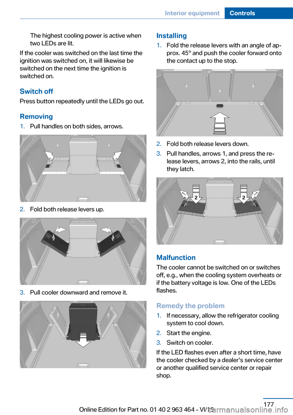
1.Pull handles on both sides, arrows.2.Fold both release levers up.3.Pull cooler downward and remove it.Installing1.Fold the release levers with an angle of ap‐
prox. 45° and push the cooler forward onto
the contact up to the stop.2.Fold both release levers down.3.Pull handles, arrows 1, and press the re‐
lease levers, arrows 2, into the rails, until
they latch.
Malfunction
The cooler cannot be switched on or switches
off, e.g., when the cooling system overheats or
if the battery voltage is low. One of the LEDs
flashes.
Remedy the problem
1.If necessary, allow the refrigerator cooling
system to cool down.2.Start the engine.3.Switch on cooler.
If the LED flashes even after a short time, have
the cooler checked by a dealer’s service center
or another qualified service center or repair
shop.
Seite 177Interior equipmentControls177
Online Edition for Part no. 01 40 2 963 464 - VI/15
Page 191 of 265
For your own safety, for the safety of passen‐
gers and of the vehicle, heed the following
points:▷Become familiar with the vehicle before
starting a trip; do not take risks in driving.▷Adjust the speed to the road surface con‐
ditions. The steeper and more uneven the
road surface, the slower the speed should
be.▷When driving on steep uphill or downhill
grades: add engine oil and coolant up to
near the MAX mark. Uphill and downhill
grades can be traveled up to no more than
50 %.▷On steep downhill grades, use Hill Descent
Control HDC, refer to page 137.
Starting out is possible on uphill grades up
to 32 %. The permissible side tilt is 50 %.▷Avoid that the chassis bottom coming in
contact with the ground.
The ground clearance is no more than 7.8
inches/20 cm and can vary according to
the vehicle's load.▷When wheels continue to spin, depress the
accelerator so that driving stability control
systems can distribute the driving force to
the wheels. Activate DTC Dynamic Trac‐
tion Control if available.
After a trip on poor roads
After a trip on poor roads, check wheels and
tires for damage to maintain driving safety.
Clear heavy soiling from the body.
Seite 191Things to remember when drivingDriving tips191
Online Edition for Part no. 01 40 2 963 464 - VI/15
Page 195 of 265
Saving fuelVehicle features and optionsThis chapter describes all standard, country-
specific and optional features offered with the
series. It also describes features that are not
necessarily available in your car, e. g., due to
the selected options or country versions. This
also applies to safety-related functions and
systems. The respectively applicable country
provisions must be observed when using the
respective features and systems.
General information Your vehicle contains advanced technology for
the reduction of fuel consumption and emis‐
sions.
Fuel consumption depends on a number of dif‐
ferent factors.
Carrying out certain measures, such as a mod‐
erate driving style and regular maintenance,
can influence fuel consumption and the envi‐
ronmental impact.
Remove unnecessary cargo
Additional weight increases fuel consumption.
Remove attached parts
following use
Remove auxiliary mirrors, roof or rear luggage
racks which are no longer required following use.
Attached parts on the vehicle impair the aero‐
dynamics and increase the fuel consumption.Close the windows and glass
sunroof
Driving with the glass sunroof and windows
open results in increased air resistance and
thereby reduces the range.
Tires
General information Tires can affect fuel consumption in various
ways, e.g., tire size may influence fuel con‐
sumption.
Check the tire inflation pressure
regularly
Check and, if needed, correct the tire inflation
pressure at least twice a month and before
starting on a long trip.
Low tire inflation pressure increases rolling re‐
sistance and thus raises fuel consumption and
tire wear.
Drive away immediately
Do not wait for the engine to warm-up while
the vehicle remains stationary. Start driving
right away, but at moderate engine speeds.
This is the quickest way of warming the cold
engine up to operating temperature.
Look well ahead when
driving
Avoid unnecessary acceleration and braking.
By maintaining a suitable distance to the vehi‐
cle driving ahead of you.
Driving smoothly and proactively reduces fuel
consumption.Seite 195Saving fuelDriving tips195
Online Edition for Part no. 01 40 2 963 464 - VI/15
Page 222 of 265
Engine oilVehicle features and options
This chapter describes all standard, country-
specific and optional features offered with the
series. It also describes features that are not
necessarily available in your car, e. g., due to
the selected options or country versions. This
also applies to safety-related functions and
systems. The respectively applicable country
provisions must be observed when using the
respective features and systems.
General information The engine oil consumption is dependent on
the driving style and driving conditions.
The engine oil consumption can increase in
the following situations, for example:▷Sporty driving style.▷Break-in of the engine.▷Idling of the engine.▷With use of engine oil types that are not
approved.
Therefore, regularly check the engine oil level
after refueling.
The vehicle is equipped with electronic oil
measurement.
The electronic oil measurement has two meas‐
uring principles:
▷Status display▷Detailed measurementElectronic oil measurement
Status display
The concept
The engine oil level is monitored electronically
while driving and shown on the Control Dis‐
play.
If the engine oil level reaches the minimum
level, a check control message is displayed.
Requirements
A current measured value is available after ap‐
prox. 30 minutes of driving. During a shorter
trip, the status of the last, sufficiently long trip
is displayed.
With frequent short-distance trips, regularly
perform a detailed measurement.
Displaying the engine oil level
On the Control Display:1."Vehicle info"2."Vehicle status"3. "Engine oil level"
Engine oil level display messages
CAUTION
A too low engine oil level causes engine
damage. There is risk of property damage. Im‐
mediately add engine oil.◀
Take care not to add too much engine oil. CAUTION
Too much engine oil can damage the en‐
gine or the catalytic converter. There is risk of
property damage. Do not add too much engine
oil. Have too much engine oil siphoned off by a
dealer’s service center or another qualified
service center or repair shop.◀
Seite 222MobilityEngine oil222
Online Edition for Part no. 01 40 2 963 464 - VI/15
Page 223 of 265
Different messages appear on the display de‐
pending on the engine oil level. Pay attention
to these messages.
If the engine oil level is too low, within the next
125 miles/200 km Add engine oil, refer to
page 223.
Detailed measurement
The concept In the detailed measurement the engine oil
level is checked and displayed via a scale.
Gasoline engine:
If the engine oil level reaches the minimum
level, a check control message is displayed.
During the measurement, the idle speed is in‐
creased somewhat.
Requirements▷Vehicle is on level road.▷Steptronic transmission: selector lever in
selector lever position N or P and accelera‐
tor pedal not depressed.▷Engine is running and is at operating tem‐
perature.
Performing a detailed measurement
In order to perform a detailed measurement of
the engine oil level:
1."Vehicle info"2."Vehicle status"3. "Measure engine oil level"4."Start measurement"
The engine oil level is checked and displayed
via a scale.
Time: approx. 1 minute.
Adding engine oil
Information CAUTION
A too low engine oil level causes engine
damage. There is risk of property damage.
Add engine oil within the next
125 miles/200 km.◀
CAUTION
Too much engine oil can damage the en‐
gine or the catalytic converter. There is risk of
property damage. Do not add too much engine
oil. Have too much engine oil siphoned off by a
dealer’s service center or another qualified
service center or repair shop.◀
WARNING
Operating materials, e.g. oils, greases,
coolants, fuels, can contain harmful ingredi‐
ents. There is risk of injuries or danger to life.
Observe the instructions on the containers.
Avoid the contact of articles of clothing, skin or
eyes with operating materials. Do not refill op‐
erating materials into different bottles. Store
operating materials out of reach of children.◀
General information
Only add engine oil when the message is dis‐
played in the instrument cluster. The quantity
to be added is indicated in the message dis‐
played in the instrument cluster.
Switch off the ignition and safely park the vehi‐
cle before engine oil is added.
Overview
The oil filler neck is located in the engine com‐
partment, refer to page 219.
Opening the oil filler neck1.Opening the hood, refer to page 220Seite 223Engine oilMobility223
Online Edition for Part no. 01 40 2 963 464 - VI/15
Page 226 of 265
CoolantVehicle features and optionsThis chapter describes all standard, country-
specific and optional features offered with the
series. It also describes features that are not
necessarily available in your car, e. g., due to
the selected options or country versions. This
also applies to safety-related functions and
systems. The respectively applicable country
provisions must be observed when using the
respective features and systems.
Information WARNING
With the engine hot and the cooling sys‐
tem open, coolant can escape and lead to
burns. There is risk of injuries. Only open the
cooling system with the engine cooled down.◀
WARNING
Additives are harmful and incorrect addi‐
tives can damage the engine. There is risk of
injuries and risk of property damage. Avoid the
contact of articles of clothing, skin or eyes with
additives. Do not swallow any additives. Use
suitable additives only.◀
Coolant consists of water and additives.
Not all commercially available additives are
suitable for the vehicle. Information about suit‐
able additives is available from a dealer’s serv‐
ice center or another qualified service center or
repair shop.
Coolant level
General information
If there is no Min. and Max. mark in the filler
neck of the coolant reservoir, have the coolant
level checked if needed by your dealer’s serv‐ice center or another qualified service center or
repair shop and add coolant as needed.
Overview
Depending on the engine installation, the cool‐
ant reservoir is located on the right side or the
left side of the engine compartment.
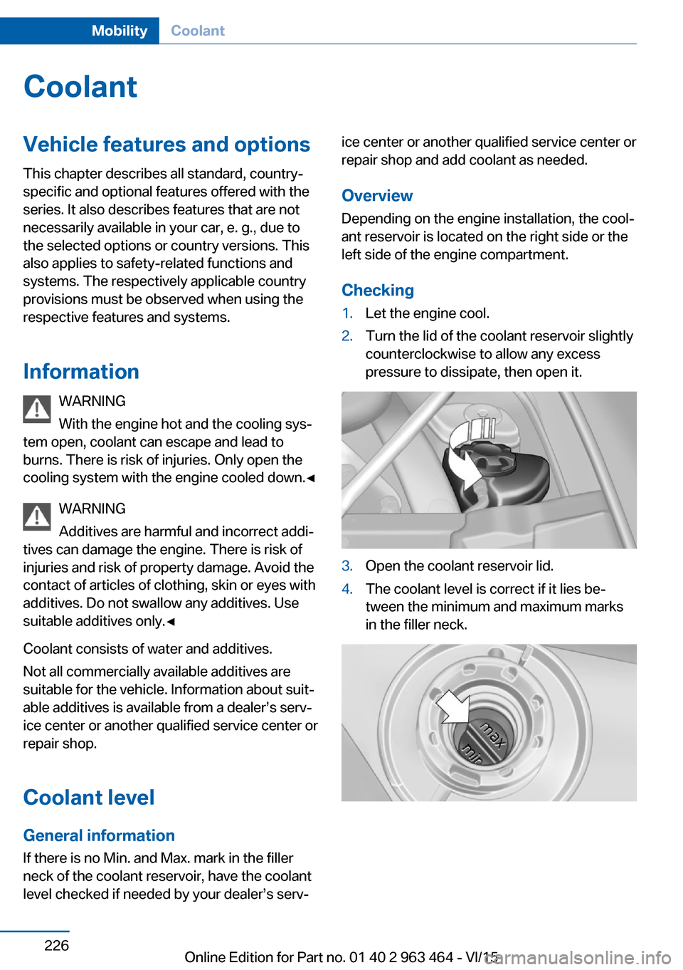
Checking1.Let the engine cool.2.Turn the lid of the coolant reservoir slightly
counterclockwise to allow any excess
pressure to dissipate, then open it.3.Open the coolant reservoir lid.4.The coolant level is correct if it lies be‐
tween the minimum and maximum marks
in the filler neck.Seite 226MobilityCoolant226
Online Edition for Part no. 01 40 2 963 464 - VI/15
Page 228 of 265
MaintenanceVehicle features and options
This chapter describes all standard, country-
specific and optional features offered with the
series. It also describes features that are not
necessarily available in your car, e. g., due to
the selected options or country versions. This
also applies to safety-related functions and
systems. The respectively applicable country
provisions must be observed when using the
respective features and systems.
BMW maintenance system The maintenance system indicates required
maintenance measures, and thereby provides
support in maintaining road safety and the op‐
erational reliability of the vehicle.
In some cases scopes and intervals may vary
according to the country-specific version. Re‐
placement work, spare parts, fuels and lubri‐
cants and wear materials are calculated sepa‐
rately. Further information is available from a
dealer’s service center or another qualified
service center or repair shop.
Condition Based ServiceCBS
Sensors and special algorithms take into ac‐
count the driving conditions of your vehicle.
Based on this, Condition Based Service recog‐
nizes the maintenance requirements.
The system makes it possible to adapt the
amount of maintenance corresponding to your
user profile.
Detailed information on service requirements,
refer to page 92, can be displayed on the Con‐
trol Display.Service data in the remote control
Information on the required maintenance is
continuously stored in the remote control. The dealer’s service center can read this data out
and suggest an optimized maintenance scope
for your vehicle.
Therefore, hand the service advisor the remote
control with which the vehicle was driven most
recently.
Storage periods Storage periods during which the vehicle bat‐
tery was disconnected are not taken into ac‐
count.
If this occurs, have a dealer's service center or
another qualified service center or repair shop
update the time-dependent maintenance pro‐
cedures, such as checking brake fluid and, if
necessary, changing the engine oil and the mi‐
crofilter/activated-charcoal filter.
Service and WarrantyInformation Booklet for US
models and Warranty and
Service Guide Booklet for
Canadian models
Please consult your Service and Warranty In‐
formation Booklet for US models and Warranty
and Service Guide Booklet for Canadian mod‐
els for additional information on service re‐
quirements.
The manufacturer of your vehicle recommends
that maintenance and repair be performed by a
dealer’s service center or another qualified
service center or repair shop. Records of regu‐
lar maintenance and repair work should be re‐
tained.Seite 228MobilityMaintenance228
Online Edition for Part no. 01 40 2 963 464 - VI/15