instrument cluster BMW X6 XDRIVE 50I 2013 Owner's Manual
[x] Cancel search | Manufacturer: BMW, Model Year: 2013, Model line: X6 XDRIVE 50I, Model: BMW X6 XDRIVE 50I 2013Pages: 345, PDF Size: 9.46 MB
Page 115 of 345
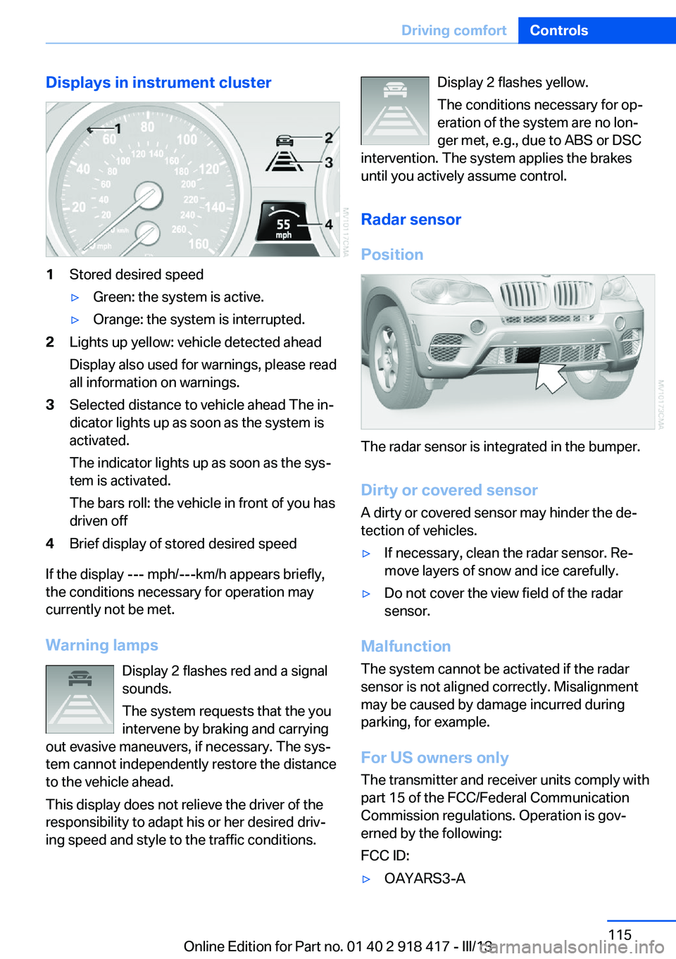
Displays in instrument cluster1Stored desired speed▷Green: the system is active.▷Orange: the system is interrupted.2Lights up yellow: vehicle detected ahead
Display also used for warnings, please read
all information on warnings.3Selected distance to vehicle ahead The in‐
dicator lights up as soon as the system is
activated.
The indicator lights up as soon as the sys‐
tem is activated.
The bars roll: the vehicle in front of you has
driven off4Brief display of stored desired speed
If the display --- mph/---km/h appears briefly,
the conditions necessary for operation may
currently not be met.
Warning lamps Display 2 flashes red and a signal
sounds.
The system requests that the you
intervene by braking and carrying
out evasive maneuvers, if necessary. The sys‐
tem cannot independently restore the distance
to the vehicle ahead.
This display does not relieve the driver of the
responsibility to adapt his or her desired driv‐
ing speed and style to the traffic conditions.
Display 2 flashes yellow.
The conditions necessary for op‐
eration of the system are no lon‐
ger met, e.g., due to ABS or DSC
intervention. The system applies the brakes
until you actively assume control.
Radar sensor
Position
The radar sensor is integrated in the bumper.
Dirty or covered sensor
A dirty or covered sensor may hinder the de‐
tection of vehicles.
▷If necessary, clean the radar sensor. Re‐
move layers of snow and ice carefully.▷Do not cover the view field of the radar
sensor.
Malfunction
The system cannot be activated if the radar
sensor is not aligned correctly. Misalignment
may be caused by damage incurred during
parking, for example.
For US owners only
The transmitter and receiver units comply with
part 15 of the FCC/Federal Communication
Commission regulations. Operation is gov‐
erned by the following:
FCC ID:
▷OAYARS3-ASeite 115Driving comfortControls115
Online Edition for Part no. 01 40 2 918 417 - III/13
Page 118 of 345
system activated, resting your foot on the acel‐
erator pedal will cause the system not to brake
even if necessary. Be certain that floormats or
other objects on the vehicle floor do not inter‐
fere with movement of the acccelerator
pedal.◀
Limits of automatic braking
While active cruise control is capable of
braking your vehicle automatically when you
approach a slower vehicle ahead, it is impor‐
tant to be aware that the ability of the system
to apply the brakes is also limited, e.g. when
you reduce your desired speed sharply. lt uses
only a portion of braking system capacity and
does not utilize the full capacity of the vehicle
braking system. Therefore, the system cannot
decrease your speed for large differences in
speed between your vehicle and the vehicle
ahead. Examples: when you approach a vehicle
traveling at a much lower speed than your own
speed such as approaching a toll booth or
when a much slower vehicle cuts in front of
you at close range.◀
Cruise controlThe concept The system is functional at speeds beginning
at approx. 20 mph/30 km/h.
The speed specified using the lever on the
steering column is maintained.
The system brakes on downhill gradients if en‐
gine braking action is insufficient.
Do not use cruise control
Do not use the system if unfavorable
conditions make it impossible to drive at a con‐
stant speed, for instance:▷On curvy roads.▷In heavy traffic.▷On slippery roads, in fog, snow or rain, or
on a loose road surface.Otherwise, you could lose control of the vehi‐
cle and cause an accident.◀
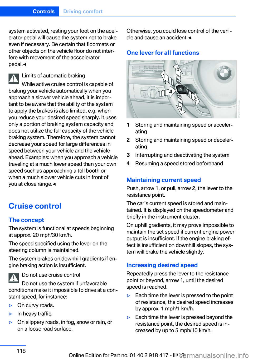
One lever for all functions1Storing and maintaining speed or acceler‐
ating2Storing and maintaining speed or deceler‐
ating3Interrupting and deactivating the system4Resuming a speed stored beforehand
Maintaining current speed
Push, arrow 1, or pull, arrow 2, the lever to the
resistance point.
The car's current speed is stored and main‐ tained. It is displayed on the speedometer and
briefly in the instrument cluster.
On uphill gradients, it may prove impossible to
maintain the set speed if current engine power
output is insufficient. If the engine braking ef‐
fect is insufficient on downhill slopes, the sys‐
tem will brake the vehicle slightly.
Increasing desired speed
Repeatedly press the lever to the resistance
point or beyond, arrow 1, until the desired
speed is reached.
▷Each time the lever is pressed to the point
of resistance, the desired speed increases
by approx. 1 mph/1 km/h.▷Each time the lever is pressed beyond the
resistance point, the desired speed is in‐
creased by up to 5 mph/10 km/h.Seite 118ControlsDriving comfort118
Online Edition for Part no. 01 40 2 918 417 - III/13
Page 119 of 345
The system stores and maintains the speed.
Accelerating using the lever Accelerating slightly:
Press the lever to the resistance point, arrow 1,
until the desired speed is reached.
Accelerating significantly:
Press the lever beyond the resistance point,
arrow 1, until the desired speed is reached.
The vehicle accelerates without pressure on
the accelerator pedal. The system stores and
maintains the speed.
Decreasing speed
Repeatedly pull the lever to the resistance
point or beyond, arrow 2, until the desired
speed is displayed.▷Each time the lever is pulled to the resist‐
ance point, the desired speed is decreased
by approx. 1 mph/1 km/h.▷Each time the lever is pulled beyond the
resistance point, the desired speed is re‐
duced by up to 5 mph/10 km/h until the
minimum speed of 20 mph/30 km/h is ach‐
ieved.
The system stores and maintains the speed.
Interrupting the system
Press the lever up or down, arrow 3: dis‐
play 1 in the speedometer changes color, refer
to page 119.
In addition, the system is interrupted:
▷When the brakes are applied.▷When the transmission position D is disen‐
gaged.▷When DTC is activated or DSC is deacti‐
vated.▷When DSC or ABS is intervening.
Warning lamp
The warning lamp lights up if cruise
control has been deactivated auto‐
matically, e.g., by a control intervention of the
DSC. A message appears on the Control Dis‐
play.
Resuming cruising speed
Press button 4:
The stored speed is resumed and maintained.
Deactivating the system▷Press the lever upward or downward twice,
arrow 3.▷Switch off the ignition.
The stored speed is cleared.
Displays in the instrument cluster
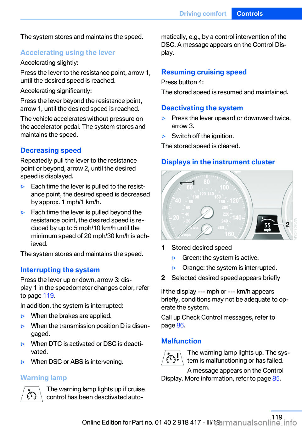
1Stored desired speed▷Green: the system is active.▷Orange: the system is interrupted.2Selected desired speed appears briefly
If the display --- mph or --- km/h appears
briefly, conditions may not be adequate to op‐
erate the system.
Call up Check Control messages, refer to
page 86.
Malfunction The warning lamp lights up. The sys‐
tem is malfunctioning or has failed.
A message appears on the Control
Display. More information, refer to page 85.
Seite 119Driving comfortControls119
Online Edition for Part no. 01 40 2 918 417 - III/13
Page 122 of 345
Malfunction
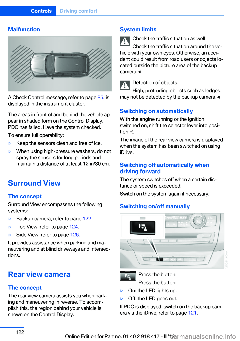
A Check Control message, refer to page 85, is
displayed in the instrument cluster.
The areas in front of and behind the vehicle ap‐
pear in shaded form on the Control Display.
PDC has failed. Have the system checked.
To ensure full operability:
▷Keep the sensors clean and free of ice.▷When using high-pressure washers, do not
spray the sensors for long periods and
maintain a distance of at least 12 in/30 cm.
Surround View
The concept Surround View encompasses the following
systems:
▷Backup camera, refer to page 122.▷Top View, refer to page 124.▷Side View, refer to page 126.
It provides assistance when parking and ma‐
neuvering and at blind driveways and intersec‐
tions.
Rear view camera
The concept The rear view camera assists you when park‐
ing and maneuvering in reverse. To accom‐
plish this, the region behind your vehicle is
shown on the Control Display.
System limits
Check the traffic situation as well
Check the traffic situation around the ve‐
hicle with your own eyes. Otherwise, an acci‐
dent could result from road users or objects lo‐
cated outside the picture area of the backup
camera.◀
Detection of objects
High, protruding objects such as ledges
may not be detected by the backup camera.◀
Switching on automatically With the engine running or the ignition
switched on, shift the selector lever into posi‐
tion R.
The image of the rear view camera is displayed
when the system has been switched on using
iDrive.
Switching off automatically when
driving forward
The system switches off when a certain dis‐
tance or speed is exceeded.
Switch on the system again if necessary.
Switching on/off manually
Press the button.
Press the button.
▷On: the LED lights up.▷Off: the LED goes out.
If PDC is displayed, switch on the backup cam‐
era via the iDrive, refer to page 121.
Seite 122ControlsDriving comfort122
Online Edition for Part no. 01 40 2 918 417 - III/13
Page 243 of 345
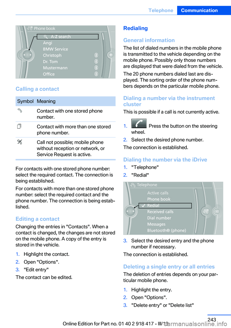
Calling a contact
SymbolMeaningContact with one stored phone
number.Contact with more than one stored
phone number.Call not possible; mobile phone
without reception or network, or
Service Request is active.
For contacts with one stored phone number:
select the required contact. The connection is
being established.
For contacts with more than one stored phone
number: select the required contact and the
phone number. The connection is being estab‐
lished.
Editing a contact Changing the entries in "Contacts". When a
contact is changed, the changes are not stored
on the mobile phone. A copy of the entry is
stored in the vehicle.
1.Highlight the contact.2.Open "Options".3."Edit entry"
The contact can be edited.
Redialing
General information
The list of dialed numbers in the mobile phone
is transmitted to the vehicle depending on the
mobile phone. Possibly only those numbers
are displayed that were dialed from the vehicle.
The 20 phone numbers dialed last are dis‐
played. The sorting order of the phone num‐
bers depends on the particular mobile phone.
Dialing a number via the instrument cluster
This is possible if a call is not currently active.1. Press the button on the steering
wheel.2.Select the desired phone number.
The connection is established.
Dialing the number via the iDrive
1."Telephone"2."Redial"3.Select the desired entry and the phone
number if necessary.
The connection is established.
Deleting a single entry or all entries The deletion of entries depends on your par‐
ticular mobile phone.
1.Highlight the entry.2.Open "Options".3."Delete entry" or "Delete list"Seite 243TelephoneCommunication243
Online Edition for Part no. 01 40 2 918 417 - III/13
Page 272 of 345
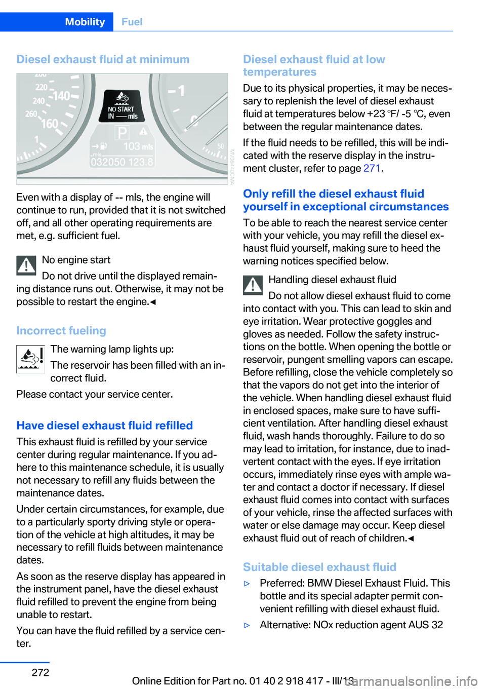
Diesel exhaust fluid at minimum
Even with a display of -- mls, the engine will
continue to run, provided that it is not switched
off, and all other operating requirements are
met, e.g. sufficient fuel.
No engine start
Do not drive until the displayed remain‐
ing distance runs out. Otherwise, it may not be
possible to restart the engine.◀
Incorrect fueling The warning lamp lights up:
The reservoir has been filled with an in‐
correct fluid.
Please contact your service center.
Have diesel exhaust fluid refilled This exhaust fluid is refilled by your service
center during regular maintenance. If you ad‐
here to this maintenance schedule, it is usually
not necessary to refill any fluids between the
maintenance dates.
Under certain circumstances, for example, due
to a particularly sporty driving style or opera‐
tion of the vehicle at high altitudes, it may be
necessary to refill fluids between maintenance
dates.
As soon as the reserve display has appeared in
the instrument panel, have the diesel exhaust
fluid refilled to prevent the engine from being
unable to restart.
You can have the fluid refilled by a service cen‐
ter.
Diesel exhaust fluid at low
temperatures
Due to its physical properties, it may be neces‐
sary to replenish the level of diesel exhaust
fluid at temperatures below +23 ℉/ -5 ℃, even
between the regular maintenance dates.
If the fluid needs to be refilled, this will be indi‐
cated with the reserve display in the instru‐
ment cluster, refer to page 271.
Only refill the diesel exhaust fluid
yourself in exceptional circumstances
To be able to reach the nearest service center
with your vehicle, you may refill the diesel ex‐
haust fluid yourself, making sure to heed the
warning notices specified below.
Handling diesel exhaust fluid
Do not allow diesel exhaust fluid to come
into contact with you. This can lead to skin and
eye irritation. Wear protective goggles and
gloves as needed. Follow the safety instruc‐
tions on the bottle. When opening the bottle or
reservoir, pungent smelling vapors can escape.
Before refilling, close the vehicle completely so
that the vapors do not get into the interior of
the vehicle. When handling diesel exhaust fluid
in enclosed spaces, make sure to have suffi‐
cient ventilation. After handling diesel exhaust
fluid, wash hands thoroughly. Failure to do so
may lead to irritation, for instance, due to inad‐
vertent contact with the eyes. If eye irritation
occurs, immediately rinse eyes with ample wa‐
ter and contact a doctor if necessary. If diesel
exhaust fluid comes into contact with surfaces
of your vehicle, rinse the affected surfaces with
water or else damage may occur. Keep diesel
exhaust fluid out of reach of children.◀
Suitable diesel exhaust fluid▷Preferred: BMW Diesel Exhaust Fluid. This
bottle and its special adapter permit con‐
venient refilling with diesel exhaust fluid.▷Alternative: NOx reduction agent AUS 32Seite 272MobilityFuel272
Online Edition for Part no. 01 40 2 918 417 - III/13
Page 305 of 345
▷When the vehicle has not been driven for
more than one month.
Starting aid terminals
Only charge using the starting aid terminals,
refer to page 309, in the engine compartment
while the engine is switched off.
Power failure
After a temporary power loss, some equipment
needs to be reinitialized.
Individual settings need to be reprogrammed:
▷Seat and mirror memory: store the posi‐
tions again, refer to page 57.▷Time: update, refer to page 87.▷Date: update, refer to page 87.▷Radio station: save again, refer to
page 192.▷Navigation system: wait for the navigation
system to be operational.▷Glass sunroof/panoramic glass sunroof: it
may only be possible to raise the roof.
Have the system initialized by the service
center.▷Digital compass: recalibrate, refer to
page 141.▷Active steering: the system automatically
initializes for a short time as you drive. Dur‐
ing this time, the system is deactivated, re‐
fer to page 110.▷xDrive: the system automatically initializes
as you drive. During this time, indicator
lamps light up. If the lamps do not disap‐
pear during the current trip, have the sys‐
tem checked.
Disposing of old batteries
Have old batteries disposed of by your
service center or bring them to a recy‐
cling center.
Maintain the battery in an upright position for
transport and storage. Secure the battery so
that it does not tip over during transport.
Fuses
Replacing fuses
Never attempt to repair a blown fuse and
do not replace a defective fuse with a substi‐
tute of another color or amperage rating; this
could lead to a circuit overload, ultimately re‐
sulting in a fire in the vehicle.◀
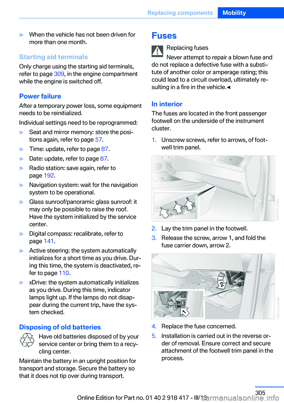
In interior The fuses are located in the front passenger
footwell on the underside of the instrument
cluster.1.Unscrew screws, refer to arrows, of foot‐
well trim panel.2.Lay the trim panel in the footwell.3.Release the screw, arrow 1, and fold the
fuse carrier down, arrow 2.4.Replace the fuse concerned.5.Installation is carried out in the reverse or‐
der of removal. Ensure correct and secure
attachment of the footwell trim panel in the
process.Seite 305Replacing componentsMobility305
Online Edition for Part no. 01 40 2 918 417 - III/13
Page 314 of 345
Clean the upholstery down to the seams using
large sweeping motions. Avoid rubbing the
material vigorously.
Damage from Velcro® fasteners
Open Velcro® fasteners on pants or
other articles of clothing can damage the seat
covers. Ensure that any Velcro® fasteners are
closed.◀
Caring for special components
Light-alloy wheels When cleaning the wheels on the vehicle, only
use a neutral wheel rim cleaner with a pH value
of 5 to 9. Do not use abrasive cleaners or a
steam jet hotter than 140 ℉/60 ℃; otherwise,
damage may result. Adhere to the manufac‐
turer instructions.
Aggressive, acidic, or alkaline cleaners may
destroy the protective coating of neighboring
components such as the brake disc.
Chrome surfaces
Carefully clean components such as the radia‐
tor grille or door handles with an ample supply
of water, possibly with shampoo added, partic‐
ularly when they have been exposed to road
salt.
Aluminum running boards
A rust film on the aluminum running boards
can be removed with a special cleaning agent.
Rubber components
Aside from water, treat only with rubber
cleansers.
When cleaning rubber seals, do not use any
silicon-containing car care products in order to
avoid damage or reduced noise damping.Fine wood parts
Clean fine wood facing and fine wood compo‐
nents only with a moist rag. Then dry with a
soft cloth.
Plastic components
These include:▷Imitation leather surfaces.▷Headliner.▷Lamp lenses.▷Instrument cluster cover.▷Matte black spray-coated components.▷Painted parts in the interior.
Clean with a microfiber cloth.
Moisten the cloth lightly with water if neces‐
sary.
Do not soak the headliner.
Do not use cleansers that contain alcohol
or solvents
Do not use cleansers that contain alcohol or
solvents, such as lacquer thinners, heavy-duty
grease removers, fuel, or such; this could lead
to surface damage.◀
Safety belts
Dirty belt straps impede the reeling action and
thus have a negative impact on safety.
No chemical cleaning
Do not clean chemically; this can destroy
the webbing.◀
Use only a mild soapy solution, with the safety
belts clipped into their buckles.
Do not allow the reels to retract the safety
belts until they are dry.
Seite 314MobilityCare314
Online Edition for Part no. 01 40 2 918 417 - III/13
Page 333 of 345
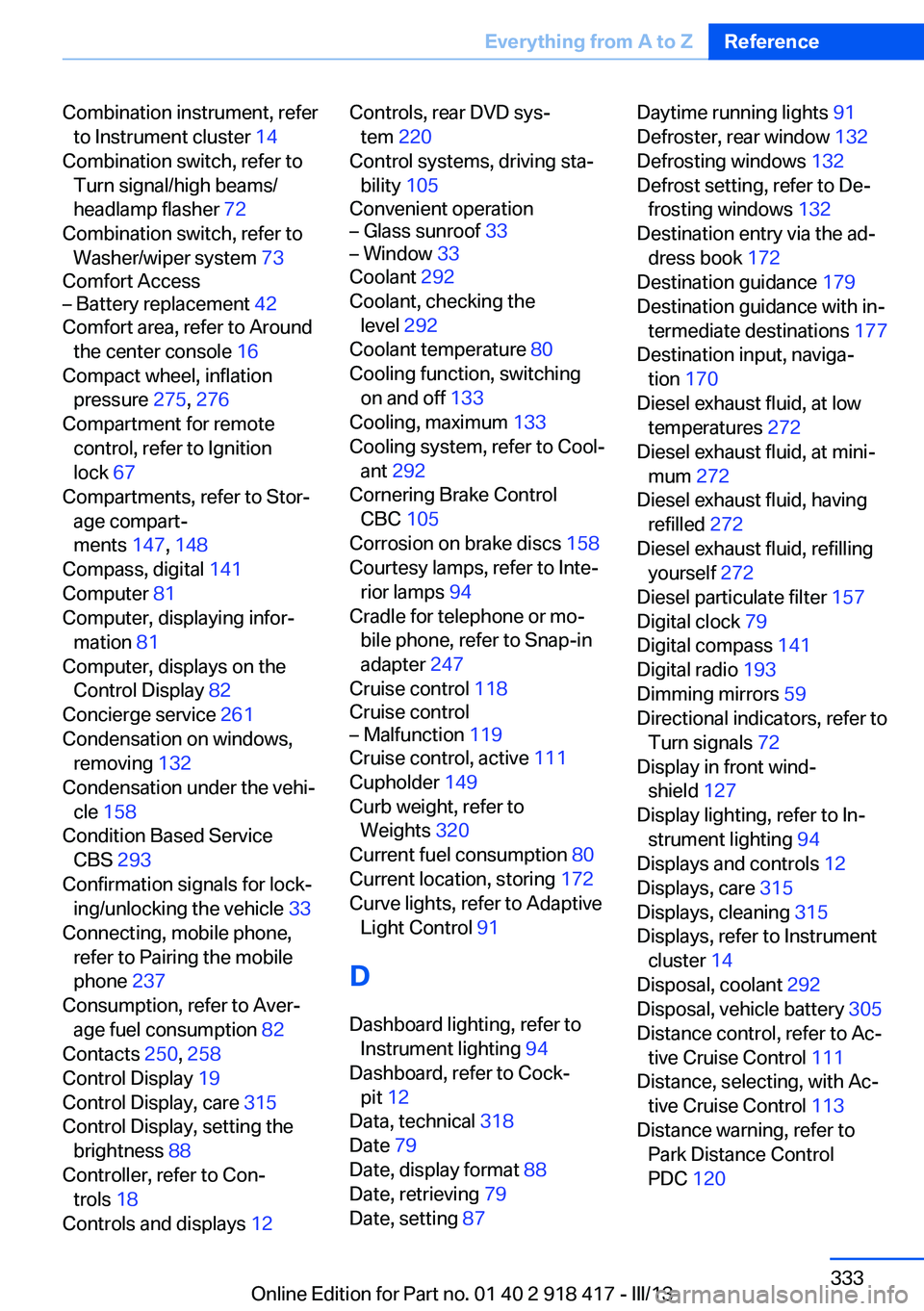
Combination instrument, referto Instrument cluster 14
Combination switch, refer to Turn signal/high beams/
headlamp flasher 72
Combination switch, refer to Washer/wiper system 73
Comfort Access– Battery replacement 42
Comfort area, refer to Around
the center console 16
Compact wheel, inflation pressure 275, 276
Compartment for remote control, refer to Ignition
lock 67
Compartments, refer to Stor‐ age compart‐
ments 147, 148
Compass, digital 141
Computer 81
Computer, displaying infor‐ mation 81
Computer, displays on the Control Display 82
Concierge service 261
Condensation on windows, removing 132
Condensation under the vehi‐ cle 158
Condition Based Service CBS 293
Confirmation signals for lock‐ ing/unlocking the vehicle 33
Connecting, mobile phone, refer to Pairing the mobile
phone 237
Consumption, refer to Aver‐ age fuel consumption 82
Contacts 250, 258
Control Display 19
Control Display, care 315
Control Display, setting the brightness 88
Controller, refer to Con‐ trols 18
Controls and displays 12
Controls, rear DVD sys‐
tem 220
Control systems, driving sta‐ bility 105
Convenient operation– Glass sunroof 33– Window 33
Coolant 292
Coolant, checking the level 292
Coolant temperature 80
Cooling function, switching on and off 133
Cooling, maximum 133
Cooling system, refer to Cool‐ ant 292
Cornering Brake Control CBC 105
Corrosion on brake discs 158
Courtesy lamps, refer to Inte‐ rior lamps 94
Cradle for telephone or mo‐ bile phone, refer to Snap-in
adapter 247
Cruise control 118
Cruise control
– Malfunction 119
Cruise control, active 111
Cupholder 149
Curb weight, refer to Weights 320
Current fuel consumption 80
Current location, storing 172
Curve lights, refer to Adaptive Light Control 91
D
Dashboard lighting, refer to Instrument lighting 94
Dashboard, refer to Cock‐ pit 12
Data, technical 318
Date 79
Date, display format 88
Date, retrieving 79
Date, setting 87
Daytime running lights 91
Defroster, rear window 132
Defrosting windows 132
Defrost setting, refer to De‐ frosting windows 132
Destination entry via the ad‐ dress book 172
Destination guidance 179
Destination guidance with in‐ termediate destinations 177
Destination input, naviga‐ tion 170
Diesel exhaust fluid, at low temperatures 272
Diesel exhaust fluid, at mini‐ mum 272
Diesel exhaust fluid, having refilled 272
Diesel exhaust fluid, refilling yourself 272
Diesel particulate filter 157
Digital clock 79
Digital compass 141
Digital radio 193
Dimming mirrors 59
Directional indicators, refer to Turn signals 72
Display in front wind‐ shield 127
Display lighting, refer to In‐ strument lighting 94
Displays and controls 12
Displays, care 315
Displays, cleaning 315
Displays, refer to Instrument cluster 14
Disposal, coolant 292
Disposal, vehicle battery 305
Distance control, refer to Ac‐ tive Cruise Control 111
Distance, selecting, with Ac‐ tive Cruise Control 113
Distance warning, refer to Park Distance Control
PDC 120 Seite 333Everything from A to ZReference333
Online Edition for Part no. 01 40 2 918 417 - III/13
Page 336 of 345
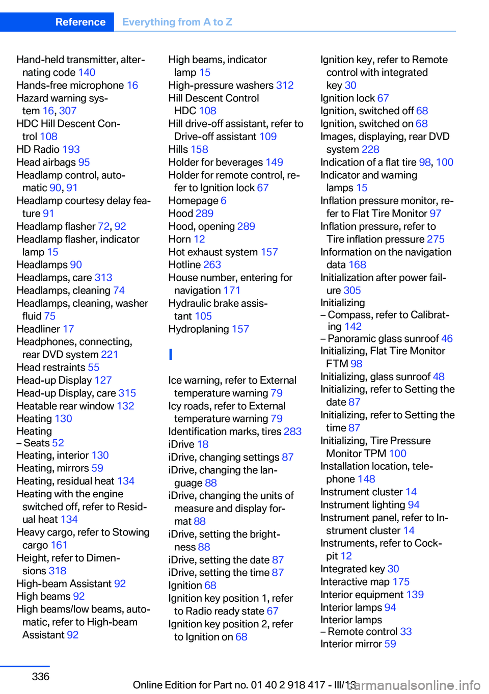
Hand-held transmitter, alter‐nating code 140
Hands-free microphone 16
Hazard warning sys‐ tem 16, 307
HDC Hill Descent Con‐ trol 108
HD Radio 193
Head airbags 95
Headlamp control, auto‐ matic 90, 91
Headlamp courtesy delay fea‐ ture 91
Headlamp flasher 72, 92
Headlamp flasher, indicator lamp 15
Headlamps 90
Headlamps, care 313
Headlamps, cleaning 74
Headlamps, cleaning, washer fluid 75
Headliner 17
Headphones, connecting, rear DVD system 221
Head restraints 55
Head-up Display 127
Head-up Display, care 315
Heatable rear window 132
Heating 130
Heating– Seats 52
Heating, interior 130
Heating, mirrors 59
Heating, residual heat 134
Heating with the engine switched off, refer to Resid‐
ual heat 134
Heavy cargo, refer to Stowing cargo 161
Height, refer to Dimen‐ sions 318
High-beam Assistant 92
High beams 92
High beams/low beams, auto‐ matic, refer to High-beam
Assistant 92
High beams, indicator
lamp 15
High-pressure washers 312
Hill Descent Control HDC 108
Hill drive-off assistant, refer to Drive-off assistant 109
Hills 158
Holder for beverages 149
Holder for remote control, re‐ fer to Ignition lock 67
Homepage 6
Hood 289
Hood, opening 289
Horn 12
Hot exhaust system 157
Hotline 263
House number, entering for navigation 171
Hydraulic brake assis‐ tant 105
Hydroplaning 157
I Ice warning, refer to External temperature warning 79
Icy roads, refer to External temperature warning 79
Identification marks, tires 283
iDrive 18
iDrive, changing settings 87
iDrive, changing the lan‐ guage 88
iDrive, changing the units of measure and display for‐
mat 88
iDrive, setting the bright‐ ness 88
iDrive, setting the date 87
iDrive, setting the time 87
Ignition 68
Ignition key position 1, refer to Radio ready state 67
Ignition key position 2, refer to Ignition on 68 Ignition key, refer to Remote
control with integrated
key 30
Ignition lock 67
Ignition, switched off 68
Ignition, switched on 68
Images, displaying, rear DVD system 228
Indication of a flat tire 98, 100
Indicator and warning lamps 15
Inflation pressure monitor, re‐ fer to Flat Tire Monitor 97
Inflation pressure, refer to Tire inflation pressure 275
Information on the navigation data 168
Initialization after power fail‐ ure 305
Initializing– Compass, refer to Calibrat‐
ing 142– Panoramic glass sunroof 46
Initializing, Flat Tire Monitor
FTM 98
Initializing, glass sunroof 48
Initializing, refer to Setting the date 87
Initializing, refer to Setting the time 87
Initializing, Tire Pressure Monitor TPM 100
Installation location, tele‐ phone 148
Instrument cluster 14
Instrument lighting 94
Instrument panel, refer to In‐ strument cluster 14
Instruments, refer to Cock‐ pit 12
Integrated key 30
Interactive map 175
Interior equipment 139
Interior lamps 94
Interior lamps
– Remote control 33
Interior mirror 59
Seite 336ReferenceEverything from A to Z336
Online Edition for Part no. 01 40 2 918 417 - III/13