brakes BMW X6 XDRIVE 50I 2014 Owners Manual
[x] Cancel search | Manufacturer: BMW, Model Year: 2014, Model line: X6 XDRIVE 50I, Model: BMW X6 XDRIVE 50I 2014Pages: 323, PDF Size: 8.36 MB
Page 8 of 323
▷Federal Emissions Performance Warranty▷California Emission Control System Lim‐
ited Warranty
Detailed information about these warranties is
listed in the Service and Warranty Information
Booklet for US models or in the Warranty and
Service Guide Booklet for Canadian models.
Your vehicle has been specifically adapted and
designed to meet the particular operating con‐
ditions and homologation requirements in your
country and continental region in order to de‐
liver the full driving pleasure while the vehicle
is operated under those conditions. If you wish
to operate your vehicle in another country or
region, you may be required to adapt your ve‐
hicle to meet different prevailing operating
conditions and homologation requirements.
You should also be aware of any applicable
warranty limitations or exclusions for such
country or region. In such case, please contact
Customer Relations for further information.
Maintenance
Maintain the vehicle regularly to sustain the
road safety, operational reliability and the New
Vehicle Limited Warranty.
Specifications for required maintenance meas‐
ures:
▷BMW Maintenance system▷Service and Warranty Information Booklet
for US models▷Warranty and Service Guide Booklet for
Canadian models
If the vehicle is not maintained according to
these specifications, this could result in seri‐
ous damage to the vehicle. Such damage is
not covered by the BMW New Vehicle Limited
Warranty.
Data memory
Numerous electronic components in your vehi‐
cle contain data memories that store technical
information on the vehicle condition, events and faults, either temporarily or permanently.
This technical information generally docu‐
ments the state of a component, a module, a
system or the environment.▷Operating conditions of system compo‐
nents, such as filling levels.▷Status messages from the vehicle and its
individual components, such as wheel rpm/
speed, motion delay, transverse accelera‐
tion.▷Malfunctions and defects in important sys‐
tem components, such as lights and
brakes.▷Vehicle responses to special driving situa‐
tions, such as airbag deployment, use of
the stability control systems.▷Ambient conditions, such as the tempera‐
ture.
These data are of a technical nature only and
are used to detect and eliminate faults and to
optimize vehicle functions. Travel profiles of
routes driven with the vehicle cannot be cre‐
ated from these data. If services are used, for
instance in the event of repairs, service proc‐
esses, warranty cases, quality assurance, etc.,
this technical information can be read out from
the event and fault data memories by service
personnel, including the manufacturer, using
special diagnosis tools. This service personnel
can provide you with more information if
needed. After troubleshooting, the information
in the fault memory is cleared or overwritten
continuously.
Situations are conceivable during the use of
the vehicle in which these technical data could
become associated with a specific person in
combination with other information, such as an
accident report, damage to the vehicle, wit‐
ness accounts, etc., possibly with the involve‐
ment of an authorized expert.
Additional functions that are contractually
agreed with the customer, such as vehicle lo‐
calization in the event of an emergency, permit
Seite 8Notes8
Online Edition for Part no. 01 40 2 910 876 - VII/13
Page 61 of 323
Set the parking brake and further secure
the vehicle as required
Set the parking brake firmly when parking; oth‐
erwise, the vehicle could roll. On steep upward
and downward inclines, further secure the ve‐
hicle, for example, by turning the steering
wheel in the direction of the curb.◀
Before driving into a car wash To make it possible for the vehicle to roll in an
automatic car wash, follow the information on
Washing in automatic car washes, refer to
page 291.
Switching off the engine
Procedure1.Engage transmission position P with the
vehicle stopped.2.Press the Start/Stop button.3.Set the parking brake.4.Remove the remote control from the igni‐
tion lock, refer to page 59.
Parking brake
The concept The parking brake is primarily intended to pre‐
vent the vehicle from rolling while parked; it
brakes the rear wheels.
The parking brake can be set manually or auto‐
matically:
▷Manual: by pulling and pushing the switch.▷Automatic: by activating Automatic Hold.Setting manually
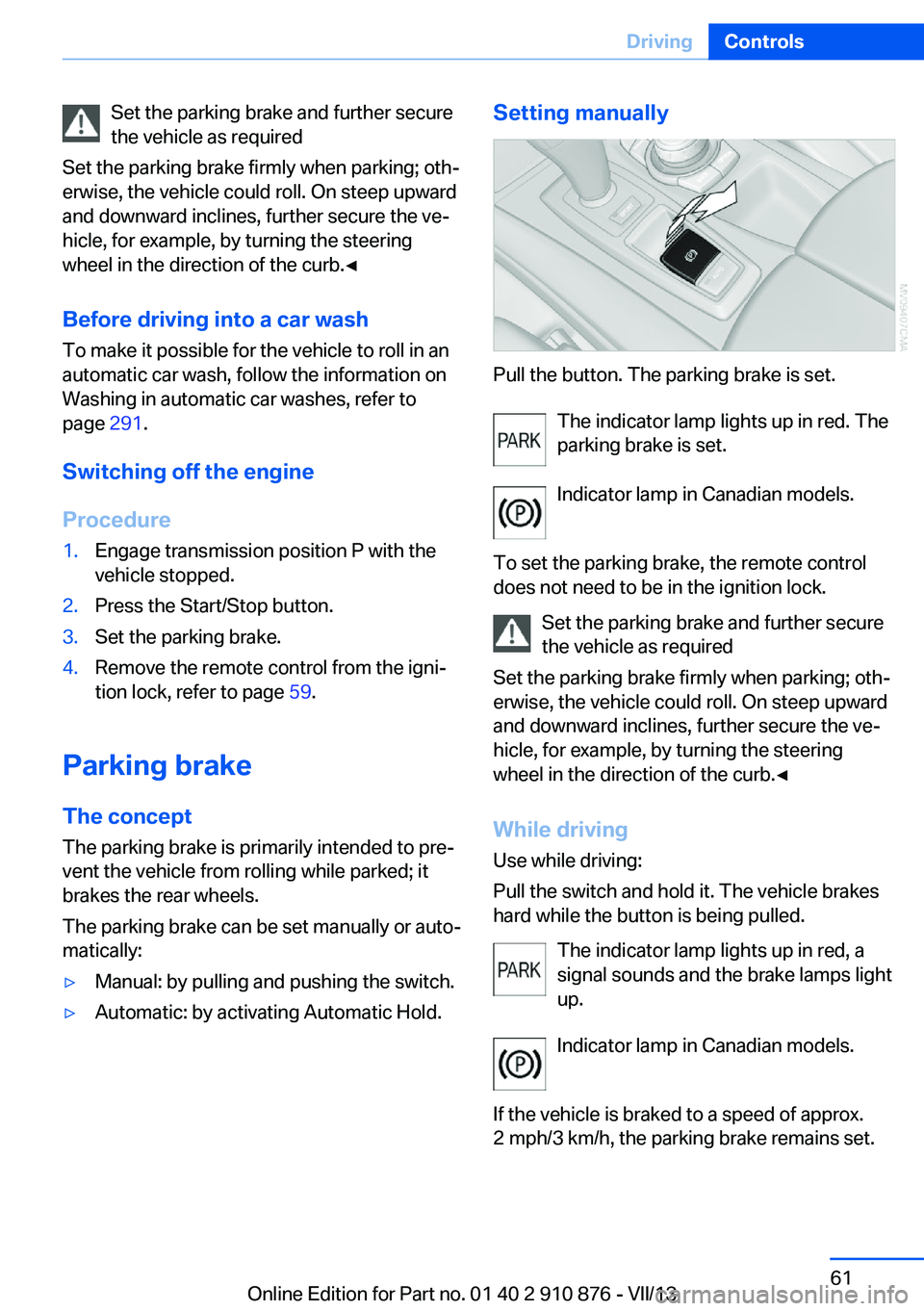
Pull the button. The parking brake is set.
The indicator lamp lights up in red. The
parking brake is set.
Indicator lamp in Canadian models.
To set the parking brake, the remote control
does not need to be in the ignition lock.
Set the parking brake and further secure
the vehicle as required
Set the parking brake firmly when parking; oth‐
erwise, the vehicle could roll. On steep upward
and downward inclines, further secure the ve‐
hicle, for example, by turning the steering
wheel in the direction of the curb.◀
While driving
Use while driving:
Pull the switch and hold it. The vehicle brakes
hard while the button is being pulled.
The indicator lamp lights up in red, a
signal sounds and the brake lamps light
up.
Indicator lamp in Canadian models.
If the vehicle is braked to a speed of approx.
2 mph/3 km/h, the parking brake remains set.
Seite 61DrivingControls61
Online Edition for Part no. 01 40 2 910 876 - VII/13
Page 96 of 323
Driving stability control systemsVehicle equipmentThis chapter describes all series equipment as
well as country-specific and special equipment
offered for this model series.Therefore, it also
describes equipment that may not be found in
your vehicle, for instance due to the selected
special equipment or the country version. This
also applies to safety-related functions and
systems.
Antilock Brake System ABS
ABS prevents locking of the wheels during
braking.
The vehicle remains steerable even during full
brake applications, thus increasing active
safety.
ABS is operational every time you start the en‐
gine.
CBC Cornering Brake
Control
When braking during curves or when braking
during a lane change, driving stability and
steering response are improved further.
Electronic brake-force
distribution
The system controls the brake pressure in the
rear wheels to ensure stable braking behavior.
Brake assistantWhen you apply the brakes rapidly, this system
automatically produces the maximum braking
force boost. It thus helps to achieve the short‐
est possible braking distance during full brak‐ing. This system utilizes all of the benefits pro‐
vided by ABS.
Do not reduce the pressure on the brake pedal
for the duration of the full braking.
Dynamic Stability Control DSC
The concept
DSC prevents traction loss in the driving
wheels when driving away and accelerating.
DSC also recognizes unstable vehicle condi‐
tions, such as fishtailing or nose-diving. Sub‐
ject to physical limits, DSC helps to keep the
vehicle on a steady course by reducing engine
speed and by applying brakes to the individual
wheels.
Adjust your driving style to the situation
An appropriate driving style is always the
responsibility of the driver.
The laws of physics cannot be repealed, even
with DSC.
Do not reduce the additional safety margin
with a risky driving style, as otherwise there is
a risk of an accident.◀
Deactivating DSC: DSC OFF
When DSC is deactivated, driving stability is
reduced during acceleration and when driving
in bends.
To increase vehicle stability, activate DSC
again as soon as possible.Seite 96ControlsDriving stability control systems96
Online Edition for Part no. 01 40 2 910 876 - VII/13
Page 99 of 323
greater the drive forces in the associated
wheel.
The transparent arrows indicate the maximum
value the drive forces over the last 10 seconds.
Malfunction
Malfunctions are displayed via Check Control,
refer to page 76.
Hill Descent Control HDC The conceptHDC is a downhill driving assistant that auto‐
matically controls vehicle speed on steep
downhill gradients. The vehicle moves at ap‐
proximately walking speed without braking in‐
tervention by the driver.
You can activate the Hill Descent Control at
speeds below approx. 22 mph/35 km/h. When
moving downhill at speeds below approx.
22 mph/35 km/h, the vehicle reduces its speed
to approximately walking speed, approx.
5 mph/8 km/h and keeps it constant.
Only use HDC in transmission positions D or R.
Increasing or reducing speed
The speed can be changed in the range from
approx. 4 mph/6 km/h to ap‐
prox. 15 mph/25 km/h by pressing the acceler‐
ator or brake pedal lightly.
A target speed within the same range can be
specified using the lever of the cruise control.
On inclines over 10 %, you can reduce the
speed to approx. 3 mph/4 km/h. Pull the lever
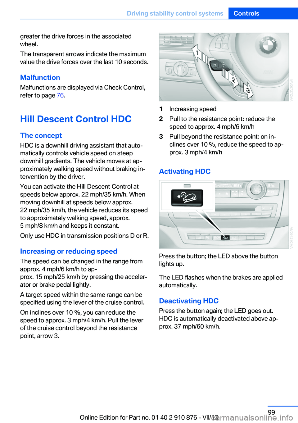
of the cruise control beyond the resistance point, arrow 3.1Increasing speed2Pull to the resistance point: reduce the
speed to approx. 4 mph/6 km/h3Pull beyond the resistance point: on in‐
clines over 10 %, reduce the speed to ap‐
prox. 3 mph/4 km/h
Activating HDC
Press the button; the LED above the button
lights up.
The LED flashes when the brakes are applied
automatically.
Deactivating HDC
Press the button again; the LED goes out.
HDC is automatically deactivated above ap‐
prox. 37 mph/60 km/h.
Seite 99Driving stability control systemsControls99
Online Edition for Part no. 01 40 2 910 876 - VII/13
Page 102 of 323
Driving comfortVehicle equipment
This chapter describes all series equipment as
well as country-specific and special equipment
offered for this model series.Therefore, it also
describes equipment that may not be found in
your vehicle, for instance due to the selected
special equipment or the country version. This
also applies to safety-related functions and
systems.
Active cruise control
With active cruise control you can select a de‐ sired speed which is then automatically main‐
tained when driving on open roadways and is
varied to maintain a selected distance setting
to slower moving vehicles ahead.
Active cruise control represents a technologi‐
cal advance over the familiar cruise control and
is a welcome relief from the constant adjust‐
ment of speed that can accompany driving in
traffic on highways or other high-speed thor‐
oughfares. Especially on longer trips and in
traffic congestion, the system can reduce fati‐
gue and tension, while increasing your enjoy‐
ment of driving. Please use it safely and re‐
sponsibly.
In addition to holding a steady cruising speed,
if you encounter slower vehicles ahead, active
cruise control will, within limits, adjust your ve‐
hicle's speed automatically so that you can
flow with the traffic without having to make
constant adjustments. If, for example, while
cruising at the selected speed, you begin to
approach a slower vehicle ahead of you in the
same lane, the system will reduce your vehi‐
cle's speed to the same as that of the vehicle
ahead to maintain your selected distance set‐
ting. You can vary the following distance,
which will vary with speed. Based on your se‐
lected distance setting, the system automati‐cally decreases the throttle setting and lightly
applies the brakes if necessary. In addition, if
the vehicle ahead of you slows to a complete
stop, the system can follow this action within
the given scope and can also accelerate from a
complete stop if the vehicle ahead of you
drives off again shortly thereafter. During brak‐
ing, your vehicle brake lamps will automatically
illuminate to alert a following driver to take ac‐
tion. In addition, it may be necessary for your
vehicle to downshift the automatic transmis‐
sion to maintain the distance setting selected.
As soon as the road in front of you has no mov‐
ing vehicles, the system will accelerate to your
desired speed. This set speed is also main‐
tained on downhill grades, however the vehicle
speed can drop below the set speed when
driving uphill if the engine output is not suffi‐
cient.
Personal responsibility
Active cruise control cannot detect stop
signs, red lights, or any object that is stopped
or is blocking the road. Active cruise control is
not and must not be used as a collision avoid‐
ance/warning system. Since this active cruise
control system is a new technology and oper‐
ates differently from conventional cruise con‐
trol systems to which you may be accustomed,
it is necessary that you read all of the pages re‐
lating to this system before use. Carefully read
and observe the information on the system
limitations, refer to page 107, to obtain a good
command of the system and its range of appli‐
cations.◀
Brake pedal feel
When the system brakes and you also depress
the brake pedal, a somewhat different braking
feel results.Seite 102ControlsDriving comfort102
Online Edition for Part no. 01 40 2 910 876 - VII/13
Page 103 of 323
Professional navigation system
If the vehicle is equipped with a Professional
navigation system, the system adapts the ac‐
celeration and deceleration behavior of the ve‐
hicle to the road on which you are currently
driving.
To ensure that the system has the latest infor‐
mation on the course of the road, use the most
recent version of the navigation data.
If the vehicle position is unknown, e.g., if you
have left the region covered by the map, the
navigation system ceases to influence vehicle
behavior.
Applications Please try the system first during sparse traffic
and clear road conditions so that you can get
used to the system. After you have experience
and understand the system, only then use it
during normal traffic.
As with conventional cruise control systems,
active cruise control in no way reduces or sub‐
stitutes for the driver's own personal experi‐
ence, responsibility, alertness and awareness
in adjusting speed, braking or otherwise con‐
trolling the vehicle. The driver should decide
when to use the system on the basis of road,
traffic, visibility, and weather conditions. Active
cruise control is intended for use on highway-
type roadways where traffic is moving rela‐
tively smoothly as well as in slow-moving traf‐
fic congestion. Do not use the system in city
driving; in complex driving situations; heavy
traffic such as during rush hour; on curvy,
winding roads, slippery roads or roads with
sharp curves such as highway off-ramps; dur‐
ing inclement weather such as snow, strong
rain or fog; or when entering interchanges,
service/parking areas or toll booths. It is also
important to regulate your vehicle's speed and
distance setting within applicable legal limits.
Always be ready to take action or apply the
brakes if necessary, especially when the sys‐
tem is actively following a vehicle in front of
you. Otherwise, driving conditions can resultwhich lead to a violation of the law or elevated
risk of an accident.
The minimum initial activation speed is
20 mph/ 30 km/h, and the maximum speed is
110 mph/ 180 km/h. The system can also be
activated while the vehicle is stationary, refer
to page 105.
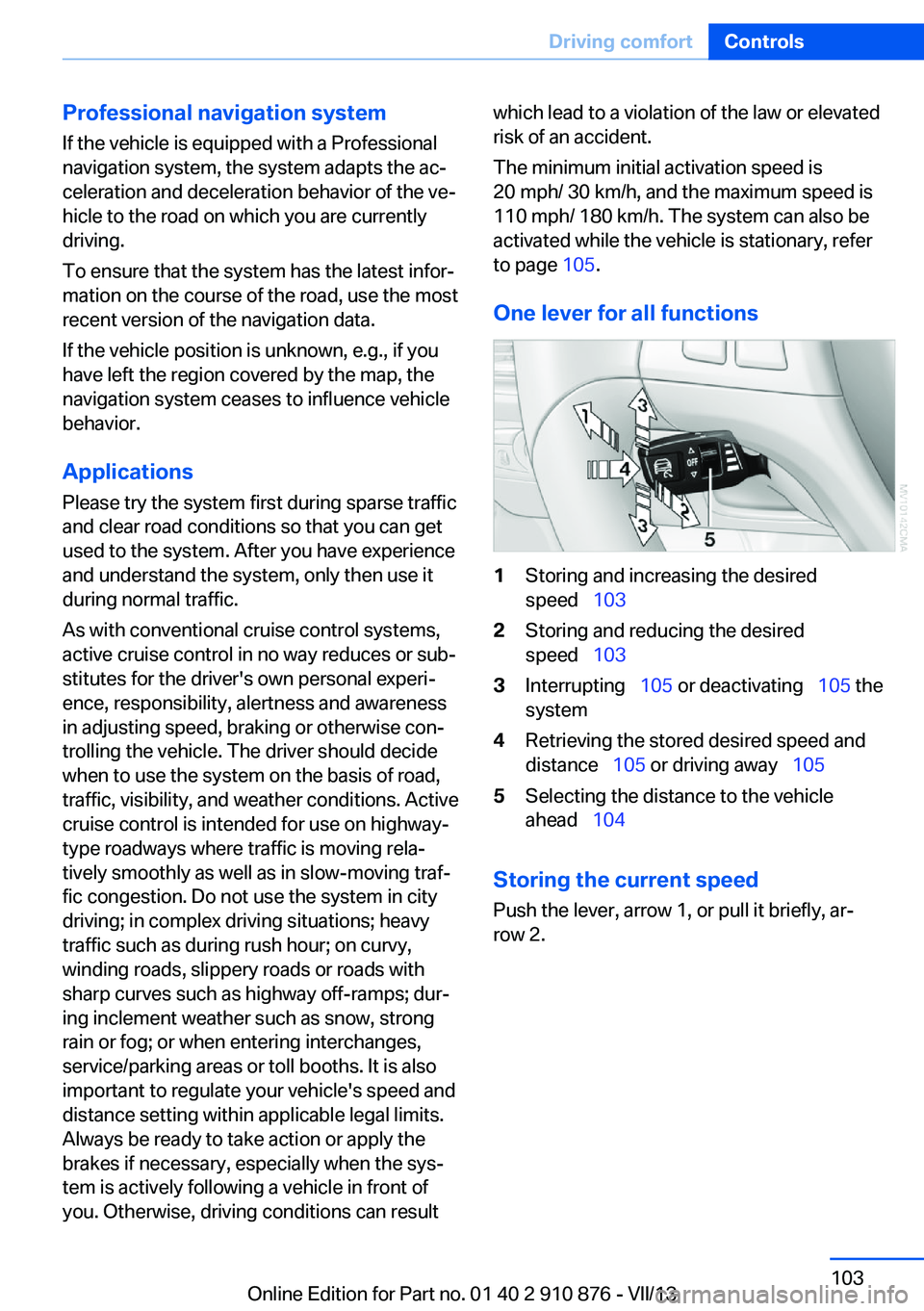
One lever for all functions1Storing and increasing the desired
speed 1032Storing and reducing the desired
speed 1033Interrupting 105 or deactivating 105 the
system4Retrieving the stored desired speed and
distance 105 or driving away 1055Selecting the distance to the vehicle
ahead 104
Storing the current speed
Push the lever, arrow 1, or pull it briefly, ar‐
row 2.
Seite 103Driving comfortControls103
Online Edition for Part no. 01 40 2 910 876 - VII/13
Page 105 of 323
Interrupting the system
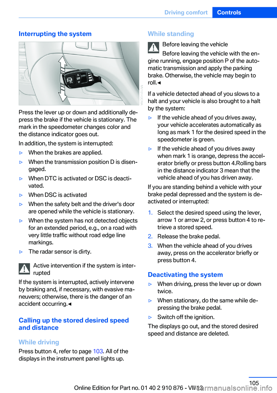
Press the lever up or down and additionally de‐
press the brake if the vehicle is stationary. The
mark in the speedometer changes color and
the distance indicator goes out.
In addition, the system is interrupted:
▷When the brakes are applied.▷When the transmission position D is disen‐
gaged.▷When DTC is activated or DSC is deacti‐
vated.▷When DSC is activated▷When the safety belt and the driver's door
are opened while the vehicle is stationary.▷When the system has not detected objects
for an extended period, e.g., on a road with
very little traffic without road edge line
markings.▷The radar sensor is dirty.
Active intervention if the system is inter‐
rupted
If the system is interrupted, actively intervene
by braking and, if necessary, with evasive ma‐
neuvers; otherwise, there is the danger of an
accident occurring.◀
Calling up the stored desired speed
and distance
While driving
Press button 4, refer to page 103. All of the
displays in the instrument panel lights up.
While standing
Before leaving the vehicle
Before leaving the vehicle with the en‐
gine running, engage position P of the auto‐
matic transmission and apply the parking
brake. Otherwise, the vehicle may begin to
roll.◀
If a vehicle detected ahead of you slows to a
halt and your vehicle is also brought to a halt
by the system:▷If the vehicle ahead of you drives away,
your vehicle accelerates automatically as
long as mark 1 for the desired speed in the
speedometer is green.▷If the vehicle ahead of you drives away
when mark 1 is orange, depress the accel‐
erator briefly or press button 4.Rolling bars
in the distance indicator 3 mean that the
vehicle ahead of you has driven away.
If you are standing behind a vehicle with your
brake pedal depressed and the system is de‐
activated or interrupted:
1.Select the desired speed using the lever,
arrow 1 or arrow 2, or press button 4 to re‐
trieve a stored speed.2.Release the brake pedal.3.When the vehicle ahead of you drives
away, press on the accelerator briefly or
press button 4.
Deactivating the system
▷When driving, press the lever up or down
twice.▷When stationary, do the same while de‐
pressing the brake pedal.▷Switch off the ignition.
The displays go out, and the stored desired
speed and distance are deleted.
Seite 105Driving comfortControls105
Online Edition for Part no. 01 40 2 910 876 - VII/13
Page 106 of 323
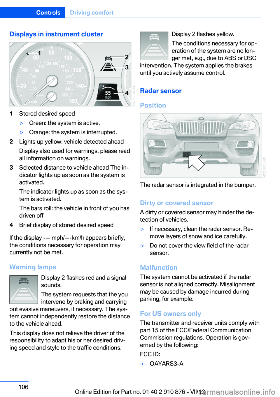
Displays in instrument cluster1Stored desired speed▷Green: the system is active.▷Orange: the system is interrupted.2Lights up yellow: vehicle detected ahead
Display also used for warnings, please read
all information on warnings.3Selected distance to vehicle ahead The in‐
dicator lights up as soon as the system is
activated.
The indicator lights up as soon as the sys‐
tem is activated.
The bars roll: the vehicle in front of you has
driven off4Brief display of stored desired speed
If the display --- mph/---km/h appears briefly,
the conditions necessary for operation may
currently not be met.
Warning lamps Display 2 flashes red and a signal
sounds.
The system requests that the you
intervene by braking and carrying
out evasive maneuvers, if necessary. The sys‐
tem cannot independently restore the distance
to the vehicle ahead.
This display does not relieve the driver of the
responsibility to adapt his or her desired driv‐
ing speed and style to the traffic conditions.
Display 2 flashes yellow.
The conditions necessary for op‐
eration of the system are no lon‐
ger met, e.g., due to ABS or DSC
intervention. The system applies the brakes
until you actively assume control.
Radar sensor
Position
The radar sensor is integrated in the bumper.
Dirty or covered sensor
A dirty or covered sensor may hinder the de‐
tection of vehicles.
▷If necessary, clean the radar sensor. Re‐
move layers of snow and ice carefully.▷Do not cover the view field of the radar
sensor.
Malfunction
The system cannot be activated if the radar
sensor is not aligned correctly. Misalignment
may be caused by damage incurred during
parking, for example.
For US owners only
The transmitter and receiver units comply with
part 15 of the FCC/Federal Communication
Commission regulations. Operation is gov‐
erned by the following:
FCC ID:
▷OAYARS3-ASeite 106ControlsDriving comfort106
Online Edition for Part no. 01 40 2 910 876 - VII/13
Page 109 of 323
system activated, resting your foot on the acel‐
erator pedal will cause the system not to brake
even if necessary. Be certain that floormats or
other objects on the vehicle floor do not inter‐
fere with movement of the acccelerator
pedal.◀
Limits of automatic braking
While active cruise control is capable of
braking your vehicle automatically when you
approach a slower vehicle ahead, it is impor‐
tant to be aware that the ability of the system
to apply the brakes is also limited, e.g. when
you reduce your desired speed sharply. lt uses
only a portion of braking system capacity and
does not utilize the full capacity of the vehicle
braking system. Therefore, the system cannot
decrease your speed for large differences in
speed between your vehicle and the vehicle
ahead. Examples: when you approach a vehicle
traveling at a much lower speed than your own
speed such as approaching a toll booth or
when a much slower vehicle cuts in front of
you at close range.◀
Cruise controlThe concept The system is functional at speeds beginning
at approx. 20 mph/30 km/h.
The speed specified using the lever on the
steering column is maintained.
The system brakes on downhill gradients if en‐
gine braking action is insufficient.
Do not use cruise control
Do not use the system if unfavorable
conditions make it impossible to drive at a con‐
stant speed, for instance:▷On curvy roads.▷In heavy traffic.▷On slippery roads, in fog, snow or rain, or
on a loose road surface.Otherwise, you could lose control of the vehi‐
cle and cause an accident.◀
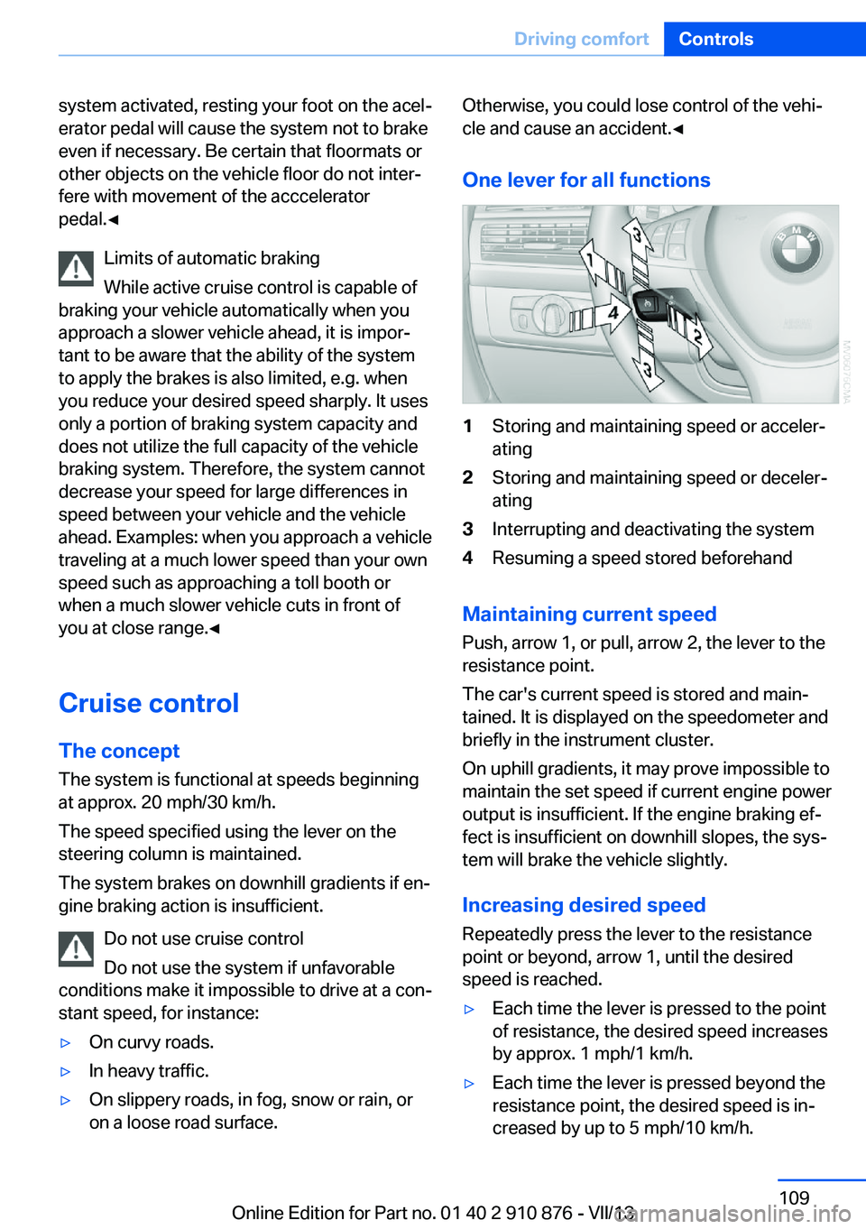
One lever for all functions1Storing and maintaining speed or acceler‐
ating2Storing and maintaining speed or deceler‐
ating3Interrupting and deactivating the system4Resuming a speed stored beforehand
Maintaining current speed
Push, arrow 1, or pull, arrow 2, the lever to the
resistance point.
The car's current speed is stored and main‐ tained. It is displayed on the speedometer and
briefly in the instrument cluster.
On uphill gradients, it may prove impossible to
maintain the set speed if current engine power
output is insufficient. If the engine braking ef‐
fect is insufficient on downhill slopes, the sys‐
tem will brake the vehicle slightly.
Increasing desired speed
Repeatedly press the lever to the resistance
point or beyond, arrow 1, until the desired
speed is reached.
▷Each time the lever is pressed to the point
of resistance, the desired speed increases
by approx. 1 mph/1 km/h.▷Each time the lever is pressed beyond the
resistance point, the desired speed is in‐
creased by up to 5 mph/10 km/h.Seite 109Driving comfortControls109
Online Edition for Part no. 01 40 2 910 876 - VII/13
Page 110 of 323
The system stores and maintains the speed.
Accelerating using the lever Accelerating slightly:
Press the lever to the resistance point, arrow 1,
until the desired speed is reached.
Accelerating significantly:
Press the lever beyond the resistance point,
arrow 1, until the desired speed is reached.
The vehicle accelerates without pressure on
the accelerator pedal. The system stores and
maintains the speed.
Decreasing speed
Repeatedly pull the lever to the resistance
point or beyond, arrow 2, until the desired
speed is displayed.▷Each time the lever is pulled to the resist‐
ance point, the desired speed is decreased
by approx. 1 mph/1 km/h.▷Each time the lever is pulled beyond the
resistance point, the desired speed is re‐
duced by up to 5 mph/10 km/h until the
minimum speed of 20 mph/30 km/h is ach‐
ieved.
The system stores and maintains the speed.
Interrupting the system
Press the lever up or down, arrow 3: dis‐
play 1 in the speedometer changes color, refer
to page 110.
In addition, the system is interrupted:
▷When the brakes are applied.▷When the transmission position D is disen‐
gaged.▷When DTC is activated or DSC is deacti‐
vated.▷When DSC or ABS is intervening.
Warning lamp
The warning lamp lights up if cruise
control has been deactivated auto‐
matically, e.g., by a control intervention of the
DSC. A message appears on the Control Dis‐
play.
Resuming cruising speed
Press button 4:
The stored speed is resumed and maintained.
Deactivating the system▷Press the lever upward or downward twice,
arrow 3.▷Switch off the ignition.
The stored speed is cleared.
Displays in the instrument cluster
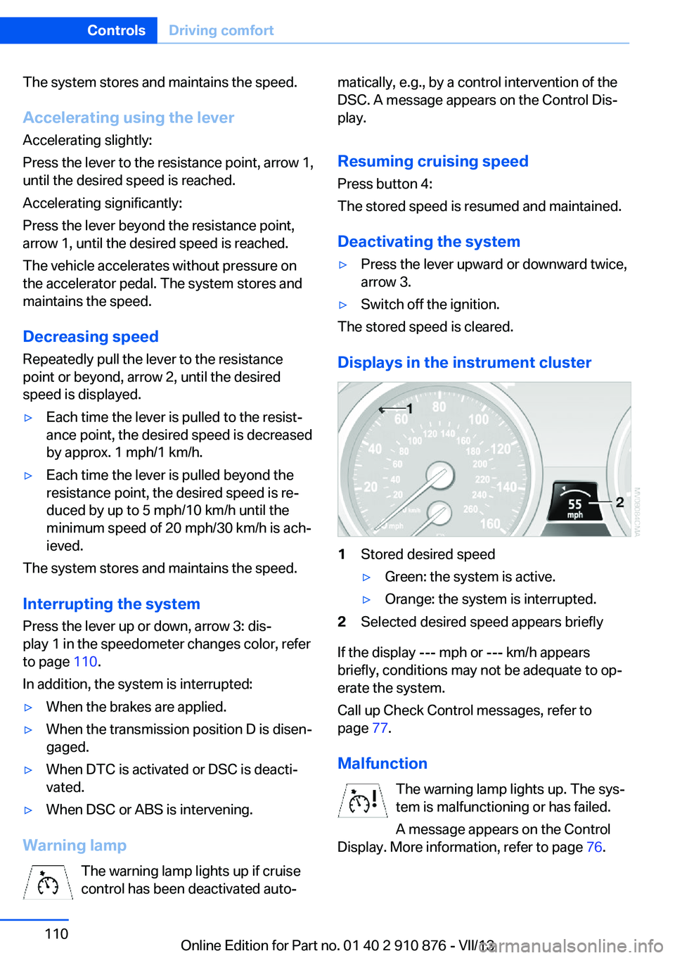
1Stored desired speed▷Green: the system is active.▷Orange: the system is interrupted.2Selected desired speed appears briefly
If the display --- mph or --- km/h appears
briefly, conditions may not be adequate to op‐
erate the system.
Call up Check Control messages, refer to
page 77.
Malfunction The warning lamp lights up. The sys‐
tem is malfunctioning or has failed.
A message appears on the Control
Display. More information, refer to page 76.
Seite 110ControlsDriving comfort110
Online Edition for Part no. 01 40 2 910 876 - VII/13