BMW X6M 2013 E71 Manual PDF
Manufacturer: BMW, Model Year: 2013, Model line: X6M, Model: BMW X6M 2013 E71Pages: 327, PDF Size: 7.71 MB
Page 71 of 327

Washer fluid reservoirAdding washer fluid
Only add washer fluid when the engine is
cool, and then close the cover completely to
avoid contact between the washer fluid and
hot engine parts.
Otherwise, there is the danger of fire and a risk
to personal safety if the fluid is spilled.◀
All washer nozzles are supplied from one res‐
ervoir.
The recommended minimum filling quantity is
0.2 US gal/1 liter.
Fill with a mixture of window washing concen‐
trate and tap water; if needed, add antifreeze
according to the manufacturer instructions.
Mix the washer fluid before adding to maintain
the correct mixing ratio.
Do not fill in undiluted window washing con‐
centrate and antifreeze and do not fill in pure
water; this could damage the washer system.
Do not mix window washing concentrate from
different manufacturers; this could cause the
washer nozzles to clog.
Automatic transmission with
Steptronic
Transmission positions
D Drive, automatic position Position for normal vehicle operation. All for‐
ward gears are available.
Under normal operating conditions, fuel con‐
sumption is lowest when you are driving in po‐
sition D.
Kickdown
Kickdown is used to achieve maximum driving
performance. Press on the accelerator beyond
the resistance point at the full throttle position.
R is Reverse Select only when the vehicle is stationary.
N is Neutral The vehicle can roll.
N remains engaged after the engine is
switched off if the remote control remains in
the ignition lock. This function can be used in
an automatic car wash, refer to page 291, for
example. P is automatically engaged after ap‐
prox. 30 minutes.
P ParkThe drive wheels are blocked.
P is engaged automatically when the following
conditions are met:▷The driver's door is opened while the en‐
gine is running, the safety belt is not fas‐
tened and neither the brake pedal nor the
accelerator is activated.▷The engine is switched off unless N is en‐
gaged and the remote control is in the igni‐
tion lock.▷The remote control is removed from the ig‐
nition lock.
Before leaving the vehicle, ensure that the
transmission position P is engaged; otherwise,
the vehicle may begin to roll.
Engaging transmission position
▷Transmission position P can only be disen‐
gaged if the engine is running and the
brake pedal is pressed.Seite 67DrivingControls67
Online Edition for Part no. 01 40 2 910 876 - VII/13
Page 72 of 327

▷With the vehicle stationary, press on the
brake pedal before shifting out of P or N;
otherwise, the shift command will not be
executed: shift lock.
Press on the brake pedal until you start
driving
To prevent the vehicle from creeping after you
select a driving position, maintain pressure on
the brake pedal until you are ready to start.◀
Engaging transmission positions D, R,
N
Briefly push the selector lever in the desired di‐
rection, beyond a resistance point if necessary.
When shifting out of P or into R, simultane‐
ously push the unlock button 1.
The engaged transmission position is dis‐
played on the selector lever.
After releasing the selector lever, it returns to
its center position.
Engaging transmission position P Select only when the vehicle is stationary.
Press button P.
Sport program and manual mode M/S
Activating the Sport program
Push the selector lever to the left out of trans‐
mission position D.
The Sport program is activated and DS or the
engaged gear is displayed in the instrument
cluster, for example S4.
This position is recommended for a perform‐
ance-oriented driving style.
Activating manual mode
Push the selector lever to the left out of trans‐
mission position D.
Push the selector lever forward or backward.
Manual mode becomes active and the gear is
changed.
The engaged gear is displayed in the instru‐
ment cluster, e.g., M1.
▷To shift down: press the selector lever for‐
ward.▷To shift up: press the selector lever back‐
ward.
The transmission only shifts up or down if the
rpm and vehicle speed are appropriate. If the
engine speed is too high, the transmission
does not shift down.
The selected gear is briefly displayed in the in‐
strument panel, followed by the current gear.
Ending the Sport program/manual
mode
Push the selector lever to the right.
Seite 68ControlsDriving68
Online Edition for Part no. 01 40 2 910 876 - VII/13
Page 73 of 327

D is displayed in the instrument cluster.Shifting gears using the shift paddles
on the steering wheel
The shifting paddles make it possible to
quickly change gears since both hands can re‐
main on the steering wheel.▷If the shift paddles on the steering wheel
are used to shift gears while in automatic
mode D, the transmission temporarily
switches to manual mode.▷If the shift paddles are not used to acceler‐
ate or shift gears for a certain amount of
time, the transmission switches back to
automatic mode D.
With the transmission position M/S selected,
the manual mode remains active.
▷Shift up: pull right shift paddle.▷Shift down: pull left shift paddle.
The vehicle only shifts up or down at appropri‐
ate engine and road speeds, e.g., it does not
shift down if the engine speed is too high.
The selected gear is briefly displayed in the in‐
strument cluster, followed by the current gear.
Displays in the instrument cluster
The transmission position is displayed and the
engaged gear, such as M4, is displayed in
manual mode.
Seite 69DrivingControls69
Online Edition for Part no. 01 40 2 910 876 - VII/13
Page 74 of 327

DisplaysVehicle equipmentThis chapter describes all series equipment as
well as country-specific and special equipment
offered for this model series.Therefore, it also
describes equipment that may not be found in
your vehicle, for instance due to the selected
special equipment or the country version. This
also applies to safety-related functions and
systems.
Odometer, external
temperature display, clock1Knob in the instrument cluster2Time, external temperature, and date3Odometer and trip odometer
Knob in the instrument cluster
Press the knob.
▷When the ignition is switched on, the trip
odometer is reset.
Press the knob for approx. 5 seconds:
View service requirement display, refer to
page 74▷When the ignition is switched off, the time,
external temperature and odometer are
displayed.Units of measure
To set the respective units of measure, miles
or km for the odometer and ℃ or ℉ for the ex‐
ternal temperature, refer to page 79.
The setting is stored for the remote control
currently in use.
Time, date, external temperature From radio readiness the external temperature
and the time are displayed.
Set the time, refer to page 78.
Retrieving date
Press the button on turn signal lever upward;
the date appears.
Set the date, refer to page 78.
Pressing the button upward or downward sev‐
eral times changes the display between clock,
external temperature, date, and Check Control
messages, refer to page 76.
External temperature warning If the display drops to +37 ℉/+3 ℃, a signal
sounds and a warning lamp lights up. There is
the increased danger of ice.
Ice on roads
Even at temperatures above
+37 ℉/+3 ℃, there can be a risk of ice on
roads.
Seite 70ControlsDisplays70
Online Edition for Part no. 01 40 2 910 876 - VII/13
Page 75 of 327

Therefore, drive carefully on bridges and shady
roads, for example, to avoid the increased dan‐
ger of an accident.◀
Odometer and trip odometer
Resetting trip odometer:
With the ignition switched on, press button 1 in
the instrument cluster.
When the vehicle is parked
If you still want to view the time, external tem‐
perature and odometer reading briefly after the
remote control has been taken out of the igni‐
tion lock:
Press button 1 in the instrument cluster.
Tachometer
Never force the engine speed up into the red
warning field, see arrow. In this range, the fuel
supply is interrupted to protect the engine.
Coolant temperature
A warning lamp will come on if the coolant, and
therefore the engine, becomes too hot. In addi‐
tion, a message will appear on the Control Dis‐
play.
Check the coolant level, refer to page 273.
Current fuel consumption
Displays the current fuel consumption. You
can check whether you are currently driving in
an efficient and environmentally-friendly man‐
ner.
Engine oil temperature
▷Cold engine: the pointer is at the low tem‐
perature end. Drive at moderate engine
and vehicle speeds.
▷Normal operating temperature: the pointer
is in the middle or in the left half of the
temperature display.
Seite 71DisplaysControls71
Online Edition for Part no. 01 40 2 910 876 - VII/13
Page 76 of 327

▷Hot engine: the pointer is at the high tem‐
perature end. Switch off the engine imme‐
diately and allow it to cool down.
If the engine oil temperature is too high, a mes‐
sage appears on the Control Display.
Check the oil level, refer to page 271.
Fuel gauge
The vehicle inclination may cause the display
to vary.
Notes on refueling, refer to page 258.
Range
After the reserve range is reached:
▷A message is briefly displayed on the Con‐
trol Display.▷The remaining range is shown on the com‐
puter.▷When a dynamic driving style is used, such
as when corners are taken rapidly, engine
functions are not ensured.
The message appears continuously below a
range of approx. 30 miles/50 km.
Refuel promptly
At the latest, refuel at a range below
30 miles/50 km; otherwise, the engine function
is not ensured and damage may occur.◀
Computer
Displaying information on the
instrument panel
Press the computer button on the turn signal
lever.
Information is displayed in the instrument clus‐
ter.
Overview of the information Repeatedly pressing the button on the turn
signal lever displays the information on the in‐
strument cluster in the following order:
▷Range.▷Average speed.▷Average fuel consumption.
To set the corresponding units of measure, re‐
fer to page 79.
Information in detail
Range
Displays the estimated cruising range available
with the remaining fuel.
It is calculated based on your driving style over
the last 18 miles/30 km.
Average speed
Periods in which the vehicle was parked and
the engine was switched off manually are not
included in the average speed calculations.
Seite 72ControlsDisplays72
Online Edition for Part no. 01 40 2 910 876 - VII/13
Page 77 of 327

With the trip computer, refer to page 73, you
can have the average speed displayed for an
additional distance.
To reset the average speed: press the button
on the turn indicator lever for approx. 2 sec‐
onds.
Average fuel consumption
This is calculated for the period during which
the engine is running.
The average consumption is computed based
on the distance traveled since the last time the
computer was reset.
You can have the average consumption for an‐
other trip displayed, refer to Displays on the
Control Display below.
To reset the average consumption: press the
button on the turn indicator lever for ap‐
prox. 2 seconds.
Displays on the Control Display
Display the computer or trip computer on the
Control Display.1."Vehicle Info"2."Onboard info" or "Trip computer"
Displays on the "Onboard info":
▷Range.▷Distance to destination.▷Estimated time of arrival if a destination
was entered in the navigation system, refer
to page 160.
Displays on the "Trip computer":
▷Departure time.▷Trip duration.▷Trip distance.
Both displays show:
▷Average fuel consumption and▷Average speed.
Resetting the fuel consumption and
speed
Resetting the values for average speed and
average fuel consumption:
1.Select the respective menu item and press
the controller.2.Press the controller again to confirm your
selection.Seite 73DisplaysControls73
Online Edition for Part no. 01 40 2 910 876 - VII/13
Page 78 of 327

Resetting the trip computerResetting all values:1."Vehicle Info"2."Trip computer"3."Reset"
Service requirements
The remaining driving distance and the date of
the next scheduled service are displayed
briefly immediately after you start the engine
or switch on the ignition.
The current service requirements can be read
out from the remote control by the service
specialist.
For certain maintenance operations, you can
view the distance remaining or the due date for
that operation in the instrument cluster.
1.With the ignition switched on, press the
knob in the instrument cluster, refer to
page 70, for approx. 5 seconds until the
service requirements are displayed.2.Press the knob repeatedly to display the
individual service requirement items.DisplaysSymbolFunctionService requirementsEngine oilRoadworthiness testFront brake padsRear brake padsBrake fluid
The sequence of displayed service items may
vary. First the data for the next maintenance
are displayed.
Seite 74ControlsDisplays74
Online Edition for Part no. 01 40 2 910 876 - VII/13
Page 79 of 327
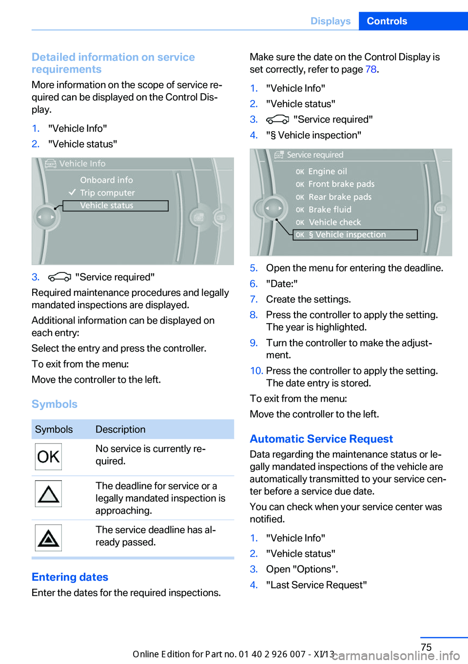
Detailed information on service
requirements
More information on the scope of service re‐
quired can be displayed on the Control Dis‐
play.1."Vehicle Info"2."Vehicle status"3. "Service required"
Required maintenance procedures and legally
mandated inspections are displayed.
Additional information can be displayed on
each entry:
Select the entry and press the controller.
To exit from the menu:
Move the controller to the left.
Symbols
SymbolsDescriptionNo service is currently re‐
quired.The deadline for service or a
legally mandated inspection is
approaching.The service deadline has al‐
ready passed.
Entering dates
Enter the dates for the required inspections.
Make sure the date on the Control Display is
set correctly, refer to page 78.1."Vehicle Info"2."Vehicle status"3. "Service required"4."§ Vehicle inspection"5.Open the menu for entering the deadline.6."Date:"7.Create the settings.8.Press the controller to apply the setting.
The year is highlighted.9.Turn the controller to make the adjust‐
ment.10.Press the controller to apply the setting.
The date entry is stored.
To exit from the menu:
Move the controller to the left.
Automatic Service Request
Data regarding the maintenance status or le‐
gally mandated inspections of the vehicle are
automatically transmitted to your service cen‐
ter before a service due date.
You can check when your service center was
notified.
1."Vehicle Info"2."Vehicle status"3.Open "Options".4."Last Service Request"Seite 75DisplaysControls75
Online Edition for Part no. 01 40 2 910 876 - VII/13
Page 80 of 327

Check Control
The concept The Check Control monitors vehicle functions
and alerts you to any malfunctions in the sys‐
tems monitored.
A Check Control message consists of indicator and warning lamps in the instrument cluster
and, in some circumstances, an acoustic signal
and text messages at the top of the Control
Display.
Indicator/warning lamps
The indicator and warning lamps can light up in
a variety of combinations and colors.
Several of the lamps are checked for proper
functioning and light up temporarily when the
engine is started or the ignition is switched on.
The symbol indicates that Check Control
messages have been stored. The Check Con‐
trol messages can be displayed later.
Text messages Text messages at the upper edge of the Con‐
trol Display in combination with a symbol in the
instrument cluster explain a Check Control
message and the meaning of the indicator and
warning lamps.
Supplementary text messages
Additional information, such as on the cause of
a fault or the required action, can be called up
via Check Control.
In urgent cases, this information will be shown
as soon as the corresponding lamp comes on.
Symbols
The following functions can be selected within
the supplementary text message, depending
on the Check Control message.▷ "Service request"
Contact the service partner.▷ "Roadside Assistance"
Contact Roadside Assistance.
Hiding Check Control messages
Press the button in the turn signal lever up or
down.
▷Some Check Control messages are dis‐
played continuously and are not cleared
until the malfunction is eliminated. If sev‐
eral malfunctions occur at once, the mes‐
sages are displayed consecutively.
These messages can be hidden for approx.
8 seconds. After this time, they are dis‐
played again automatically.▷Other Check Control messages are hidden
automatically after approx. 20 seconds.Seite 76ControlsDisplays76
Online Edition for Part no. 01 40 2 910 876 - VII/13