BMW X6M 2014 F86 Repair Manual
Manufacturer: BMW, Model Year: 2014, Model line: X6M, Model: BMW X6M 2014 F86Pages: 251, PDF Size: 7.35 MB
Page 61 of 251
Distance
Adjust the distance so that the head restraint is as close as possible to the back of the head.
Active head restraint
In the event of a rear-end collision with a cer‐
tain severity, the active head restraint automat‐
ically reduces the distance from the head.
Reduced protective function▷Do not use seat or head restraint
covers.▷Do not hang objects, e.g., clothes hangers,
on the head restraints.▷Only attach accessories approved by BMW
to the seat or head restraint.
Otherwise, the protective function of the active
head restraint will be impaired and the per‐
sonal safety of the occupants will be endan‐
gered.◀
Wear and tear after accidents or when dam‐
aged otherwise:
Have the active headrest checked and if
needed replaced.
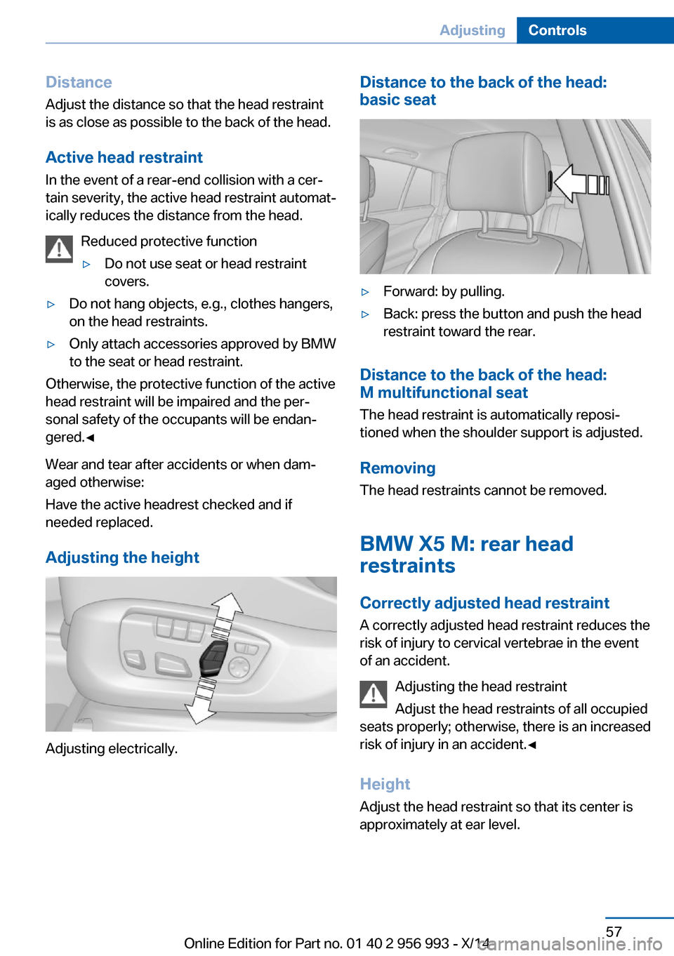
Adjusting the height
Adjusting electrically.
Distance to the back of the head:
basic seat▷Forward: by pulling.▷Back: press the button and push the head
restraint toward the rear.
Distance to the back of the head:
M multifunctional seat
The head restraint is automatically reposi‐
tioned when the shoulder support is adjusted.
Removing The head restraints cannot be removed.
BMW X5 M: rear head
restraints
Correctly adjusted head restraint
A correctly adjusted head restraint reduces the
risk of injury to cervical vertebrae in the event
of an accident.
Adjusting the head restraint
Adjust the head restraints of all occupied
seats properly; otherwise, there is an increased
risk of injury in an accident.◀
Height
Adjust the head restraint so that its center is
approximately at ear level.
Seite 57AdjustingControls57
Online Edition for Part no. 01 40 2 956 993 - X/14
Page 62 of 251
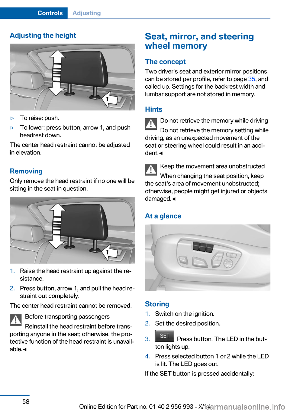
Adjusting the height▷To raise: push.▷To lower: press button, arrow 1, and push
headrest down.
The center head restraint cannot be adjusted
in elevation.
RemovingOnly remove the head restraint if no one will be
sitting in the seat in question.
1.Raise the head restraint up against the re‐
sistance.2.Press button, arrow 1, and pull the head re‐
straint out completely.
The center head restraint cannot be removed.
Before transporting passengers
Reinstall the head restraint before trans‐
porting anyone in the seat; otherwise, the pro‐
tective function of the head restraint is unavail‐
able.◀
Seat, mirror, and steering
wheel memory
The concept
Two driver's seat and exterior mirror positions
can be stored per profile, refer to page 35, and
called up. Settings for the backrest width and
lumbar support are not stored in memory.
Hints Do not retrieve the memory while driving
Do not retrieve the memory setting while
driving, as an unexpected movement of the
seat or steering wheel could result in an acci‐
dent.◀
Keep the movement area unobstructed
When changing the seat position, keep
the seat's area of movement unobstructed;
otherwise, people might get injured or objects
damaged.◀
At a glance
Storing
1.Switch on the ignition.2.Set the desired position.3. Press button. The LED in the but‐
ton lights up.4.Press selected button 1 or 2 while the LED
is lit. The LED goes out.
If the SET button is pressed accidentally:
Seite 58ControlsAdjusting58
Online Edition for Part no. 01 40 2 956 993 - X/14
Page 63 of 251
Press button again.
The LED goes out.
Calling up settings
Comfort function1.Open the driver's door.2.Switch off the ignition.3.Briefly press the desired button 1 or 2.
The corresponding seat position is performed
automatically.
The procedure stops when a reel for adjusting
the seat or one of the buttons is pressed.
Safety mode
1.Close the driver's door or reel on the igni‐
tion.2.Press and hold the desired button 1 or 2
until the adjustment procedure is com‐
pleted.
Calling up of a seat position
deactivated
After a brief period, calling up stored seat posi‐
tions is deactivated to save battery power.
To reactivate calling up of a seat position:
▷Open or close the door or tailgate.▷Press a button on the remote control.▷Press the Start/Stop button.
Mirrors
Exterior mirrors
General information The mirror on the passenger side is more
curved than the driver's side mirror.
Depending on the vehicle equipment, the mir‐
ror setting is stored for the profile currently in
use. When the vehicle is unlocked via the re‐
mote control, the position is automatically re‐
trieved if this function is active.
Note Estimating distances correctly
Objects reflected in the mirror are closer
than they appear. Do not estimate the distance
to the traffic behind you based on what you
see in the mirror, as this will increase your risk
of an accident.◀
At a glance1Adjusting 592Left/right, Automatic Curb Monitor3Fold in and out 60
Selecting a mirror
To change over to the other mirror:
Slide the switch.
Adjusting electrically The setting corresponds to the direc‐
tion in which the button is pressed.
Saving positions
Seat, mirror, and steering wheel memory, refer
to page 58.
Adjusting manually In case of electrical malfunction press edges of
mirror.
Seite 59AdjustingControls59
Online Edition for Part no. 01 40 2 956 993 - X/14
Page 64 of 251
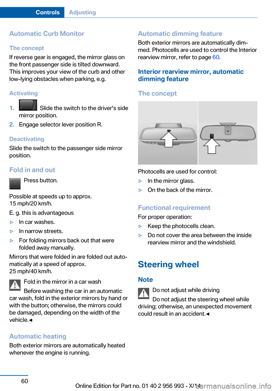
Automatic Curb MonitorThe concept
If reverse gear is engaged, the mirror glass on
the front passenger side is tilted downward.
This improves your view of the curb and other
low-lying obstacles when parking, e.g.
Activating1. Slide the switch to the driver's side
mirror position.2.Engage selector lever position R.
Deactivating
Slide the switch to the passenger side mirror
position.
Fold in and out Press button.
Possible at speeds up to approx.
15 mph/20 km/h.
E. g. this is advantageous
▷In car washes.▷In narrow streets.▷For folding mirrors back out that were
folded away manually.
Mirrors that were folded in are folded out auto‐
matically at a speed of approx.
25 mph/40 km/h.
Fold in the mirror in a car wash
Before washing the car in an automatic
car wash, fold in the exterior mirrors by hand or
with the button; otherwise, the mirrors could
be damaged, depending on the width of the
vehicle.◀
Automatic heating
Both exterior mirrors are automatically heated
whenever the engine is running.
Automatic dimming feature
Both exterior mirrors are automatically dim‐
med. Photocells are used to control the Interior
rearview mirror, refer to page 60.
Interior rearview mirror, automatic
dimming feature
The concept
Photocells are used for control:
▷In the mirror glass.▷On the back of the mirror.
Functional requirement For proper operation:
▷Keep the photocells clean.▷Do not cover the area between the inside
rearview mirror and the windshield.
Steering wheel
Note Do not adjust while driving
Do not adjust the steering wheel while
driving; otherwise, an unexpected movement
could result in an accident.◀
Seite 60ControlsAdjusting60
Online Edition for Part no. 01 40 2 956 993 - X/14
Page 65 of 251
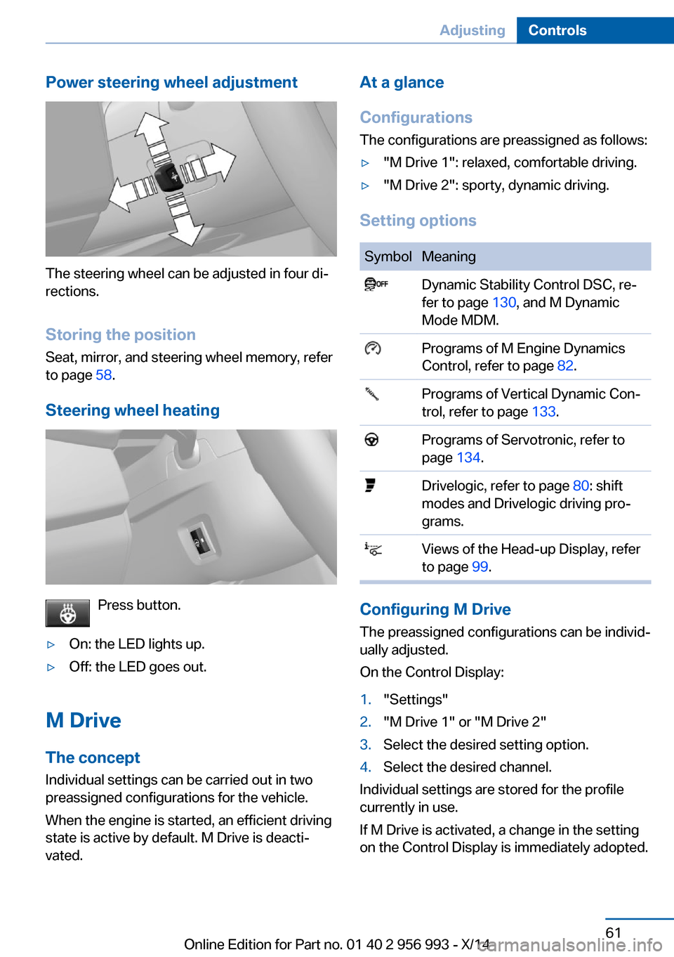
Power steering wheel adjustment
The steering wheel can be adjusted in four di‐
rections.
Storing the position Seat, mirror, and steering wheel memory, refer
to page 58.
Steering wheel heating
Press button.
▷On: the LED lights up.▷Off: the LED goes out.
M Drive The conceptIndividual settings can be carried out in two
preassigned configurations for the vehicle.
When the engine is started, an efficient driving
state is active by default. M Drive is deacti‐
vated.
At a glance
Configurations
The configurations are preassigned as follows:▷"M Drive 1": relaxed, comfortable driving.▷"M Drive 2": sporty, dynamic driving.
Setting options
SymbolMeaning Dynamic Stability Control DSC, re‐
fer to page 130, and M Dynamic
Mode MDM. Programs of M Engine Dynamics
Control, refer to page 82. Programs of Vertical Dynamic Con‐
trol, refer to page 133. Programs of Servotronic, refer to
page 134. Drivelogic, refer to page 80: shift
modes and Drivelogic driving pro‐
grams. Views of the Head-up Display, refer
to page 99.
Configuring M Drive
The preassigned configurations can be individ‐
ually adjusted.
On the Control Display:
1."Settings"2."M Drive 1" or "M Drive 2"3.Select the desired setting option.4.Select the desired channel.
Individual settings are stored for the profile
currently in use.
If M Drive is activated, a change in the setting
on the Control Display is immediately adopted.
Seite 61AdjustingControls61
Online Edition for Part no. 01 40 2 956 993 - X/14
Page 66 of 251
Activating/deactivating M Drive
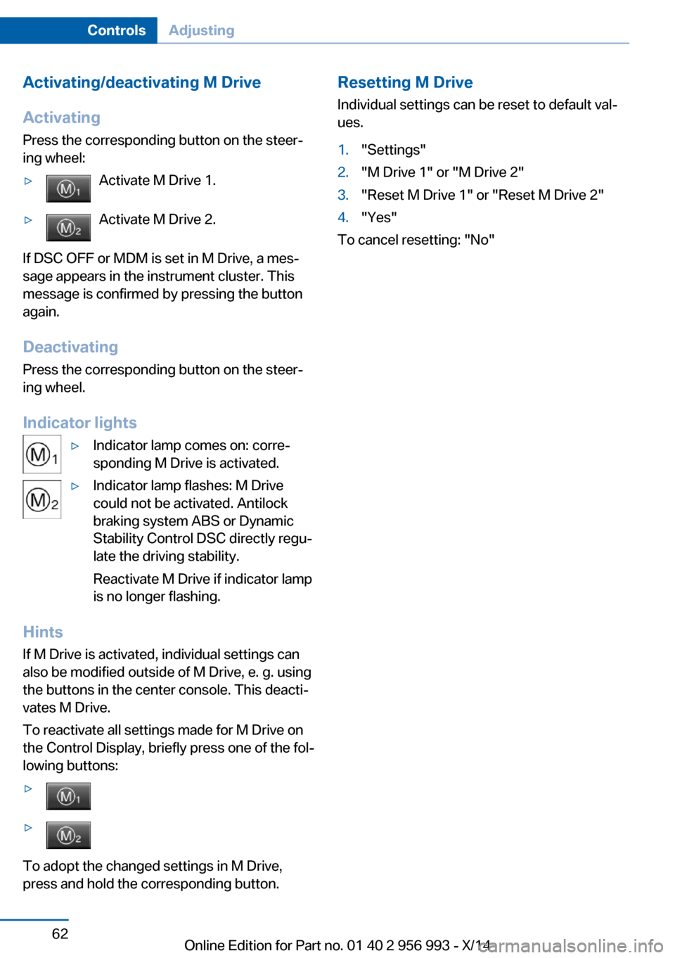
Activating Press the corresponding button on the steer‐
ing wheel:▷Activate M Drive 1.▷Activate M Drive 2.
If DSC OFF or MDM is set in M Drive, a mes‐
sage appears in the instrument cluster. This
message is confirmed by pressing the button
again.
Deactivating Press the corresponding button on the steer‐
ing wheel.
Indicator lights
▷Indicator lamp comes on: corre‐
sponding M Drive is activated.▷Indicator lamp flashes: M Drive
could not be activated. Antilock
braking system ABS or Dynamic
Stability Control DSC directly regu‐
late the driving stability.
Reactivate M Drive if indicator lamp
is no longer flashing.
Hints
If M Drive is activated, individual settings can
also be modified outside of M Drive, e. g. using
the buttons in the center console. This deacti‐
vates M Drive.
To reactivate all settings made for M Drive on
the Control Display, briefly press one of the fol‐
lowing buttons:
▷▷
To adopt the changed settings in M Drive,
press and hold the corresponding button.
Resetting M Drive
Individual settings can be reset to default val‐
ues.1."Settings"2."M Drive 1" or "M Drive 2"3."Reset M Drive 1" or "Reset M Drive 2"4."Yes"
To cancel resetting: "No"
Seite 62ControlsAdjusting62
Online Edition for Part no. 01 40 2 956 993 - X/14
Page 67 of 251
Transporting children safelyVehicle features and optionsThis chapter describes all standard, country-
specific and optional features offered with the
series. It also describes features that are notnecessarily available in your car, e. g., due to
the selected options or country versions. This
also applies to safety-related functions and
systems.
The right place for children
Note
Children in the vehicle
Do not leave children unattended in the
vehicle; otherwise, they could endanger them‐
selves and other persons, e.g., by opening the
doors.◀
Children should always be in the rear Accident research shows that the safest place
for children is in the back seat.
Transporting children in the rear
Only transport children younger than
13 years of age or shorter than 5 ft/150 cm in
the rear in child restraint systems provided in
accordance with the age, weight and size of
the child; otherwise, there is an increased risk
of injury in an accident.
Children 13 years of age or older must wear a
safety belt as soon as a suitable child restraint
system can no longer be used due to their age,
weight and size.◀
Children on the front passenger seat
Should it ever be necessary to use a child re‐
straint system in the front passenger seat,
make sure that the front, knee and side airbags
on the front passenger side are deactivated.
Automatic deactivation of front-seat passen‐
ger airbags, refer to page 108.Note
Deactivating the front-seat passenger
airbags
If a child restraint system is used in the front
passenger seat, deactivate the front-seat pas‐
senger airbags; otherwise, there is an in‐
creased risk of injury to the child when the air‐
bags are activated, even with a child restraint
system.◀
Installing child restraint
systems
Hints Manufacturer's information for child re‐straint systems
To select, mount and use child restraint sys‐
tems, observe the information provided by the
system manufacturer; otherwise, the protec‐
tive effect can be lost.◀
Ensuring the stability of the child seat
When installing child restraint systems,
make sure that the child seat is securely fas‐
tened to the backrest of the seat. Angle and
headrest of the backrest might need to be ad‐
justed or possibly be removed. Make sure that
all backrests are securely locked. Otherwise
the stability of the child seat can be affected,
and there is an increased risk of injury becauseSeite 63Transporting children safelyControls63
Online Edition for Part no. 01 40 2 956 993 - X/14
Page 68 of 251
of unexpected movement of the rear seat
backrest.◀
On the front passenger seat
Deactivating airbags Deactivating the front-seat passenger
airbags
If a child restraint system is used in the front
passenger seat, deactivate the front-seat pas‐
senger airbags; otherwise, there is an in‐
creased risk of injury to the child when the air‐
bags are activated, even with a child restraint
system.◀
After installing a child restraint system in the
front passenger seat, make sure that the front,
knee and side airbags on the front passenger
side are deactivated.
Deactivate the front-seat passenger airbags
automatically, refer to page 108.
Seat position and height
Before installing a child restraint system, move
the front passenger seat as far back as possi‐
ble and adjust its height to the highest and
thus best possible position for the belt and to
offer optimal protection in the event of an acci‐
dent.
If the upper anchorage of the safety belt is lo‐
cated in front of the belt guide of the child seat,
move the passenger seat carefully forward un‐
til the best possible belt guide position is
reached.
Backrest width Backrest width for the child seat
Before installing a child restraint system
in the front passenger seat, the backrest width
must be opened completely. Do not changethe adjustment after this; otherwise, the stabil‐
ity of the child seat will be reduced.◀
Adjustable backrest width: before installing a
child restraint system in the front passenger
seat, open the backrest width completely. Do
not change the backrest width again and do
not call up a memory position.
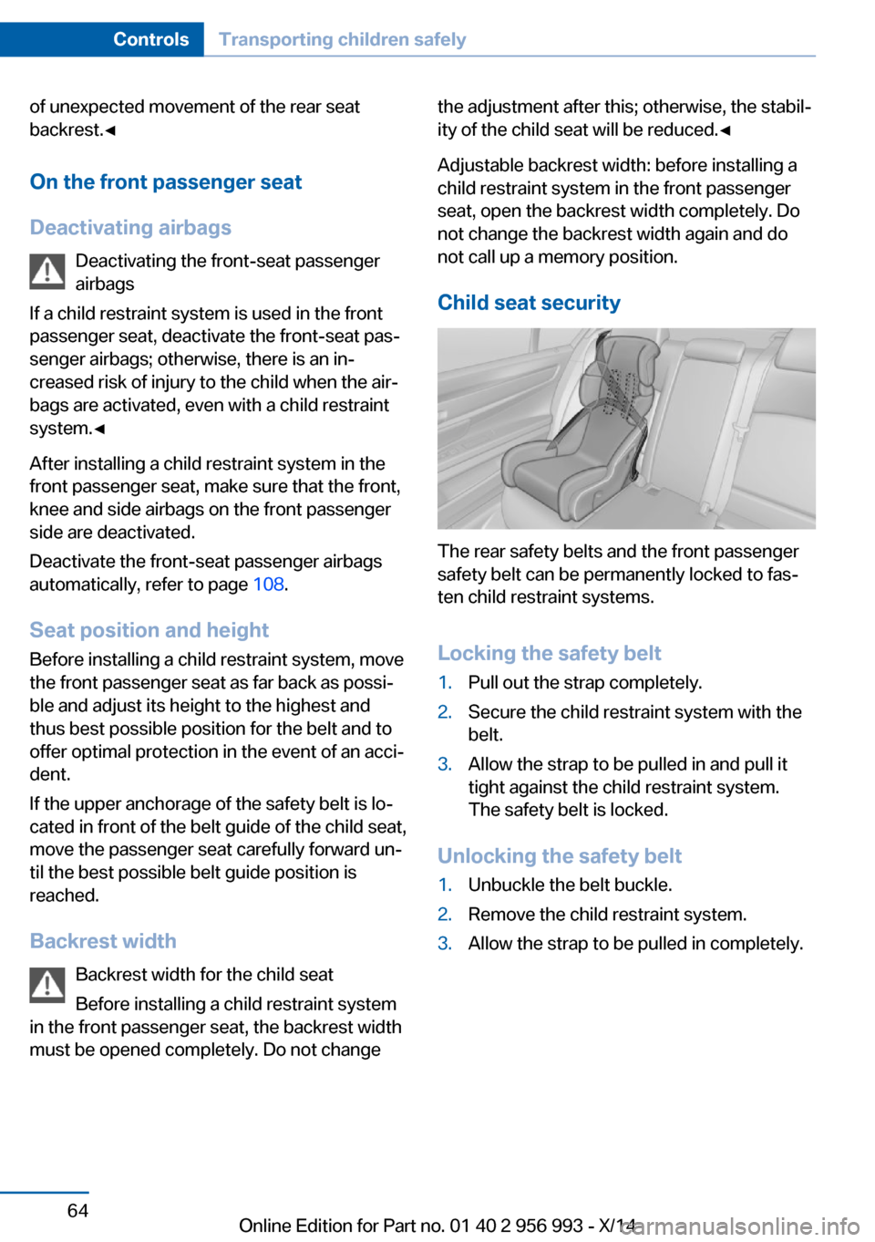
Child seat security
The rear safety belts and the front passenger
safety belt can be permanently locked to fas‐
ten child restraint systems.
Locking the safety belt
1.Pull out the strap completely.2.Secure the child restraint system with the
belt.3.Allow the strap to be pulled in and pull it
tight against the child restraint system.
The safety belt is locked.
Unlocking the safety belt
1.Unbuckle the belt buckle.2.Remove the child restraint system.3.Allow the strap to be pulled in completely.Seite 64ControlsTransporting children safely64
Online Edition for Part no. 01 40 2 956 993 - X/14
Page 69 of 251
LATCH child restraint systemLATCH: Lower Anchors and Tether for Chil‐
dren.
Note Follow manufacturer's information for
LATCH child restraint systems
To mount and use the LATCH child restraint
systems, observe the operating and safety in‐
formation from the system manufacturer; oth‐
erwise, the level of protection may be re‐
duced.◀
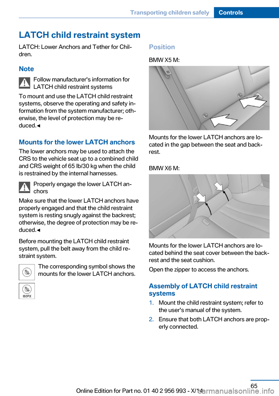
Mounts for the lower LATCH anchors
The lower anchors may be used to attach the
CRS to the vehicle seat up to a combined child
and CRS weight of 65 lb/30 kg when the child
is restrained by the internal harnesses.
Properly engage the lower LATCH an‐
chors
Make sure that the lower LATCH anchors have
properly engaged and that the child restraint
system is resting snugly against the backrest; otherwise, the degree of protection may be re‐
duced.◀
Before mounting the LATCH child restraint
system, pull the belt away from the child re‐
straint system.
The corresponding symbol shows the
mounts for the lower LATCH anchors.PositionBMW X5 M:
Mounts for the lower LATCH anchors are lo‐
cated in the gap between the seat and back‐
rest.
BMW X6 M:
Mounts for the lower LATCH anchors are lo‐
cated behind the seat cover between the back‐
rest and the seat cushion.
Open the zipper to access the anchors.
Assembly of LATCH child restraint
systems
1.Mount the child restraint system; refer to
the user's manual of the system.2.Ensure that both LATCH anchors are prop‐
erly connected.Seite 65Transporting children safelyControls65
Online Edition for Part no. 01 40 2 956 993 - X/14
Page 70 of 251
Child restraint fixing system with a
tether strap
Mounting points
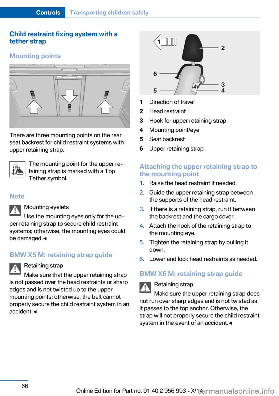
There are three mounting points on the rear
seat backrest for child restraint systems with
upper retaining strap.
The mounting point for the upper re‐
taining strap is marked with a Top
Tether symbol.
Note Mounting eyelets
Use the mounting eyes only for the up‐
per retaining strap to secure child restraint
systems; otherwise, the mounting eyes could
be damaged.◀
BMW X5 M: retaining strap guide Retaining strap
Make sure that the upper retaining strap
is not passed over the head restraints or sharp
edges and is not twisted up to the upper
mounting points; otherwise, the belt cannot
properly secure the child restraint system in an
accident.◀
1Direction of travel2Head restraint3Hook for upper retaining strap4Mounting point/eye5Seat backrest6Upper retaining strap
Attaching the upper retaining strap to
the mounting point
1.Raise the head restraint if needed.2.Guide the upper retaining strap between
the supports of the head restraint.3.If there is a retaining strap, run it between
the backrest and the cargo cover.4.Attach the hook of the retaining strap to
the mounting eye.5.Tighten the retaining strap by pulling it
down.6.Lower and lock head restraints as needed.
BMW X6 M: retaining strap guide
Retaining strap
Make sure the upper retaining strap does
not run over sharp edges and is not twisted as
it passes to the top anchor. Otherwise, the
strap will not properly secure the child restraint
system in the event of an accident.◀
Seite 66ControlsTransporting children safely66
Online Edition for Part no. 01 40 2 956 993 - X/14