service indicator BMW Z4 SDRIVE28I 2013 Owners Manual
[x] Cancel search | Manufacturer: BMW, Model Year: 2013, Model line: Z4 SDRIVE28I, Model: BMW Z4 SDRIVE28I 2013Pages: 220, PDF Size: 9.9 MB
Page 14 of 220
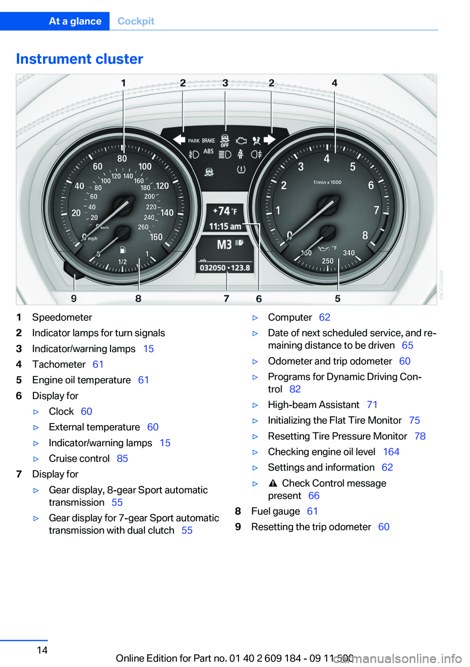
Instrument cluster1Speedometer2Indicator lamps for turn signals3Indicator/warning lamps‚ÄÇ‚ÄÖ154Tachometer‚ÄÇ‚ÄÖ615Engine oil temperature‚ÄÇ‚ÄÖ 616Display for‚ñ∑Clock‚ÄÇ‚ÄÖ60‚ñ∑External temperature‚ÄÇ‚ÄÖ 60‚ñ∑Indicator/warning lamps‚ÄÇ‚ÄÖ 15‚ñ∑Cruise control‚ÄÇ‚ÄÖ857Display for‚ñ∑Gear display, 8-gear Sport automatic
transmission‚ÄÇ‚ÄÖ 55‚ñ∑Gear display for 7-gear Sport automatic
transmission with dual clutch‚ÄÇ‚ÄÖ 55‚ñ∑Computer‚ÄÇ‚ÄÖ62‚ñ∑Date of next scheduled service, and re‚Äê
maining distance to be driven‚ÄÇ‚ÄÖ 65‚ñ∑Odometer and trip odometer‚ÄÇ‚ÄÖ60‚ñ∑Programs for Dynamic Driving Con‚Äê
trol‚ÄÇ‚ÄÖ 82‚ñ∑High-beam Assistant‚ÄÇ‚ÄÖ 71‚ñ∑Initializing the Flat Tire Monitor‚ÄÇ‚ÄÖ 75‚ñ∑Resetting Tire Pressure Monitor‚ÄÇ‚ÄÖ 78‚ñ∑Checking engine oil level‚ÄÇ‚ÄÖ164‚ñ∑Settings and information‚ÄÇ‚ÄÖ62‚ñ∑ Check Control message
present‚ÄÇ‚ÄÖ 668Fuel gauge‚ÄÇ‚ÄÖ 619Resetting the trip odometer‚ÄÇ‚ÄÖ 60Seite 14At a glanceCockpit14
Online Edition for Part no. 01 40 2 609 184 - 09 11 500
Page 39 of 220
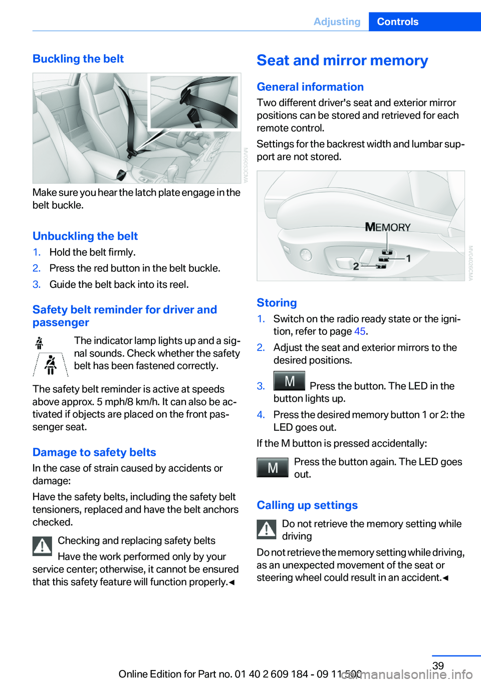
Buckling the belt
Make sure you hear the latch plate engage in the
belt buckle.
Unbuckling the belt
1.Hold the belt firmly.2.Press the red button in the belt buckle.3.Guide the belt back into its reel.
Safety belt reminder for driver and
passenger
The indicator lamp lights up and a sig‚Äê
nal sounds. Check whether the safety
belt has been fastened correctly.
The safety belt reminder is active at speeds
above approx. 5 mph/8 km/h. It can also be ac‚Äê
tivated if objects are placed on the front pas‚Äê
senger seat.
Damage to safety belts
In the case of strain caused by accidents or
damage:
Have the safety belts, including the safety belt
tensioners, replaced and have the belt anchors
checked.
Checking and replacing safety belts
Have the work performed only by your
service center; otherwise, it cannot be ensured
that this safety feature will function properly.‚óÄ
Seat and mirror memory
General information
Two different driver's seat and exterior mirror
positions can be stored and retrieved for each
remote control.
Settings for the backrest width and lumbar sup‚Äê
port are not stored.
Storing
1.Switch on the radio ready state or the igni‚Äê
tion, refer to page 45.2.Adjust the seat and exterior mirrors to the
desired positions.3. Press the button. The LED in the
button lights up.4.Press the desired memory button 1 or 2: the
LED goes out.
If the M button is pressed accidentally:
Press the button again. The LED goes
out.
Calling up settings Do not retrieve the memory setting while
driving
Do not retrieve the memory setting while driving,
as an unexpected movement of the seat or
steering wheel could result in an accident.‚óÄ
Seite 39AdjustingControls39
Online Edition for Part no. 01 40 2 609 184 - 09 11 500
Page 63 of 220
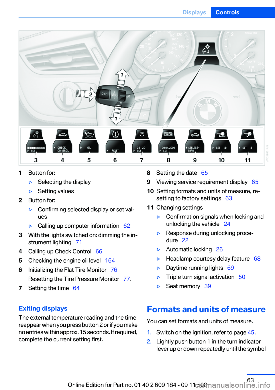
1Button for:‚ñ∑Selecting the display‚ñ∑Setting values2Button for:‚ñ∑Confirming selected display or set val‚Äê
ues‚ñ∑Calling up computer information‚ÄÇ‚ÄÖ 623With the lights switched on: dimming the in‚Äê
strument lighting‚ÄÇ‚ÄÖ 714Calling up Check Control‚ÄÇ‚ÄÖ 665Checking the engine oil level‚ÄÇ‚ÄÖ 1646Initializing the Flat Tire Monitor‚ÄÇ‚ÄÖ 76
Resetting the Tire Pressure Monitor‚ÄÇ‚ÄÖ 77.7Setting the time‚ÄÇ‚ÄÖ 648Setting the date‚ÄÇ‚ÄÖ 659Viewing service requirement display‚ÄÇ‚ÄÖ 6510Setting formats and units of measure, re‚Äê
setting to factory settings‚ÄÇ‚ÄÖ 6311Changing settings‚ñ∑Confirmation signals when locking and
unlocking the vehicle‚ÄÇ‚ÄÖ 24‚ñ∑Response during unlocking proce‚Äê
dure‚ÄÇ‚ÄÖ 22‚ñ∑Automatic locking‚ÄÇ‚ÄÖ 26‚ñ∑Headlamp courtesy delay feature‚ÄÇ‚ÄÖ 68‚ñ∑Daytime running lights‚ÄÇ‚ÄÖ69‚ñ∑Triple turn signal activation‚ÄÇ‚ÄÖ 50‚ñ∑Seat memory‚ÄÇ‚ÄÖ39Exiting displays
The external temperature reading and the time
reappear when you press button 2 or if you make
no entries within approx. 15 seconds. If required,
complete the current setting first.Formats and units of measure
You can set formats and units of measure.1.Switch on the ignition, refer to page 45.2.Lightly push button 1 in the turn indicator
lever up or down repeatedly until the symbolSeite 63DisplaysControls63
Online Edition for Part no. 01 40 2 609 184 - 09 11 500
Page 65 of 220
symbol appears in the display, accompanied
by the time and the word "SET".2.Press button 2.3.Use button 1 to set the hours.4.Press button 2 to confirm the entry.5.Use button 1 to set the minutes.6.Press button 2 to confirm the entry.7.Press button 2.
The system accepts the new time.
Date
Setting the date
To set the dd/mm or mm/dd date format, formats
and units of measure, refer to page 63.
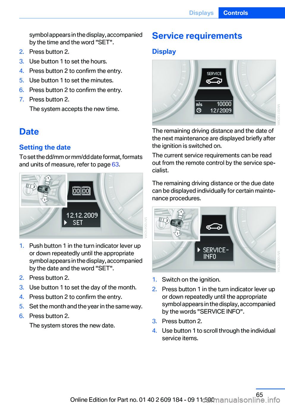
1.Push button 1 in the turn indicator lever up
or down repeatedly until the appropriate
symbol appears in the display, accompanied
by the date and the word "SET".2.Press button 2.3.Use button 1 to set the day of the month.4.Press button 2 to confirm the entry.5.Set the month and the year in the same way.6.Press button 2.
The system stores the new date.Service requirements
Display
The remaining driving distance and the date of
the next maintenance are displayed briefly after
the ignition is switched on.
The current service requirements can be read
out from the remote control by the service spe‚Äê
cialist.
The remaining driving distance or the due date
can be displayed individually for certain mainte‚Äê
nance procedures.
1.Switch on the ignition.2.Press button 1 in the turn indicator lever up
or down repeatedly until the appropriate
symbol appears in the display, accompanied
by the words "SERVICE INFO".3.Press button 2.4.Use button 1 to scroll through the individual
service items.Seite 65DisplaysControls65
Online Edition for Part no. 01 40 2 609 184 - 09 11 500
Page 66 of 220
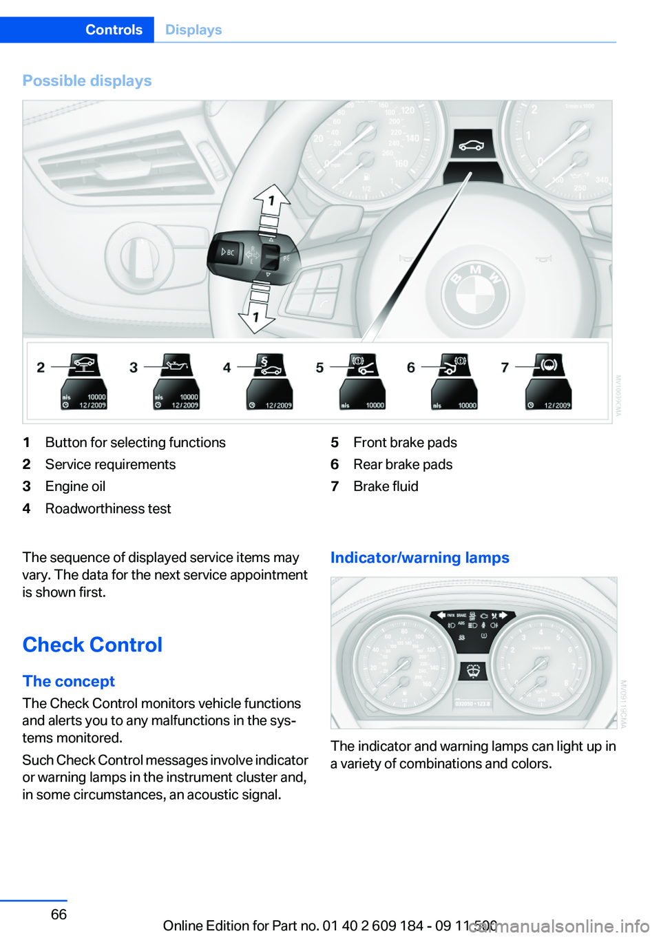
Possible displays1Button for selecting functions2Service requirements3Engine oil4Roadworthiness test5Front brake pads6Rear brake pads7Brake fluidThe sequence of displayed service items may
vary. The data for the next service appointment
is shown first.
Check Control
The concept
The Check Control monitors vehicle functions
and alerts you to any malfunctions in the sys‚Äê
tems monitored.
Such Check Control messages involve indicator
or warning lamps in the instrument cluster and,
in some circumstances, an acoustic signal.Indicator/warning lamps
The indicator and warning lamps can light up in
a variety of combinations and colors.
Seite 66ControlsDisplays66
Online Edition for Part no. 01 40 2 609 184 - 09 11 500
Page 74 of 220
‚ñ∑Do not hang pieces of clothing, such as jack‚Äê
ets, over the backrests.‚ñ∑Make sure that passengers do not lean their
heads against the side airbag; otherwise, se‚Äê
rious injuries could result if the airbag sud‚Äê
denly deployed.‚ñ∑Do not remove the airbag restraint system.‚ñ∑Do not remove the steering wheel.‚ñ∑Do not apply adhesive materials to the air‚Äê
bag cover panels, cover them or modify
them in any way.‚ñ∑Never modify either the individual compo‚Äê
nents or the wiring in the airbag system. This
also applies to the covers of the steering
wheel, the dashboard and the seats.‚óÄ
In the case of a malfunction, deactivation
and after triggering of the airbags
Do not touch the individual components imme‚Äê
diately after the system has been triggered; oth‚Äê
erwise, there is the danger of burns.
Only have the airbags checked, repaired or dis‚Äê
mantled and the airbag generator scrapped by
your service center or a workshop that has the
necessary authorization for handling explosives.
Non-professional attempts to service the sys‚Äê
tem could lead to failure in an emergency or un‚Äê
desired triggering of the airbag, either of which
could result in injury.‚óÄ
Warning notices and information about the air‚Äê
bags can also be found on the sun visors.
Automatic deactivation of the
passenger airbags
The system determines whether the front pas‚Äê
senger seat is occupied by measuring the re‚Äê
sistance of the human body. The front and side
airbags on the front passenger side are acti‚Äê
vated or deactivated accordingly by the system.
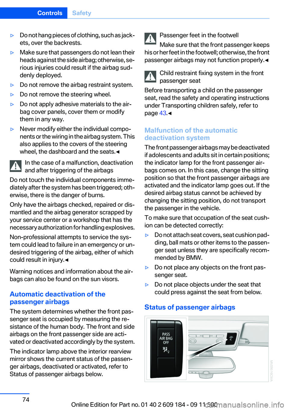
The indicator lamp above the interior rearview
mirror shows the current status of the passen‚Äê
ger airbags, deactivated or activated, refer to
Status of passenger airbags below.
Passenger feet in the footwell
Make sure that the front passenger keeps
his or her feet in the footwell; otherwise, the front
passenger airbags may not function properly.‚óÄ
Child restraint fixing system in the front
passenger seat
Before transporting a child on the passenger
seat, read the safety and operating instructions
under Transporting children safely, refer to
page 43.‚óÄ
Malfunction of the automatic
deactivation system
The front passenger airbags may be deactivated
if adolescents and adults sit in certain positions;
the indicator lamp for the front passenger air‚Äê
bags comes on. In this case, change the sitting
position so that the front passenger airbags are
activated and the indicator lamp goes out. If the
desired airbag status cannot be achieved by
changing the sitting position, do not transport
the passenger in the vehicle.
To make sure that occupation of the seat cush‚Äê
ion can be detected correctly:‚ñ∑Do not attach seat covers, seat cushion pad‚Äê
ding, ball mats or other items to the passen‚Äê
ger seat unless they are specifically recom‚Äê
mended by BMW.‚ñ∑Do not place any objects on the front pas‚Äê
senger seat.‚ñ∑Do not place objects under the seat that
could press against the seat from below.
Status of passenger airbags
Seite 74ControlsSafety74
Online Edition for Part no. 01 40 2 609 184 - 09 11 500
Page 80 of 220
‚ñ∑A wheel without TPM electronics is fitted:
have the service center check it if necessary.‚ñ∑Malfunction: have the system checked by
your service center.‚ñ∑TPM could not be fully reset. Reset the sys‚Äê
tem again.
The small warning lamp flashes in yel‚Äê
low and then lights up continuously;
the larger warning lamp comes on in
yellow. No flat tire can be detected.
Display in the following situations:
‚ñ∑Disturbance by systems or devices with the
same radio frequency. After leaving the area
of the disturbance, the system automatically
becomes active again.
Declaration according to NHTSA/
FMVSS 138 Tire Pressure Monitoring
Systems
Each tire, including the spare (if provided)
should be checked monthly when cold and in‚Äê
flated to the inflation pressure recommended by
the vehicle manufacturer on the vehicle placard
or tire inflation pressure label (If your vehicle has
tires of a different size than the size indicated on
the vehicle placard or tire inflation pressure la‚Äê
bel, you should determine the proper tire infla‚Äê
tion pressure for those tires.).
As an added safety feature, your vehicle has
been equipped with a tire pressure monitoring
system (TPMS) that illuminates a low tire pres‚Äê
sure telltale when one or more of your tires is
significantly under-inflated. Accordingly, when
the low tire pressure telltale illuminates, you
should stop and check your tires as soon as
possible, and inflate them to the proper pres‚Äê
sure. Driving on a significantly under-inflated tire
causes the tire to overheat and can lead to tire
failure. Under-inflation also reduces fuel effi‚Äê
ciency and tire tread life, and may affect the ve‚Äê
hicle's handling and stopping ability.
Please note that the TPMS is not a substitute for
proper tire maintenance, and it is the driver's re‚Äê
sponsibility to maintain correct tire pressure,
even if under-inflation has not reached the level
to trigger illumination of the TPMS low tire pres‚Äê
sure telltale.
Your vehicle has also been equipped with a
TPMS malfunction indicator to indicate when
the system is not operating properly. The TPMS
malfunction indicator is combined with the low
tire pressure telltale. When the system detects
a malfunction, the telltale will flash for approxi‚Äê
mately one minute and then remain continu‚Äê
ously illuminated. This sequence will continue
upon subsequent vehicle start-ups as long as
the malfunction exists. When the malfunction
indicator is illuminated, the system may not be
able to detect or signal low tire pressure as in‚Äê
tended. TPMS malfunctions may occur for a va‚Äê
riety of reasons, including the installation of re‚Äê
placement or alternate tires or wheels on the
vehicle that prevent the TPMS from functioning
properly. Always check the TPMS malfunction
telltale after replacing one or more tires or
wheels on your vehicle to ensure that the re‚Äê
placement or alternate tires and wheels allow
the TPMS to continue to function properly.
Brake force display
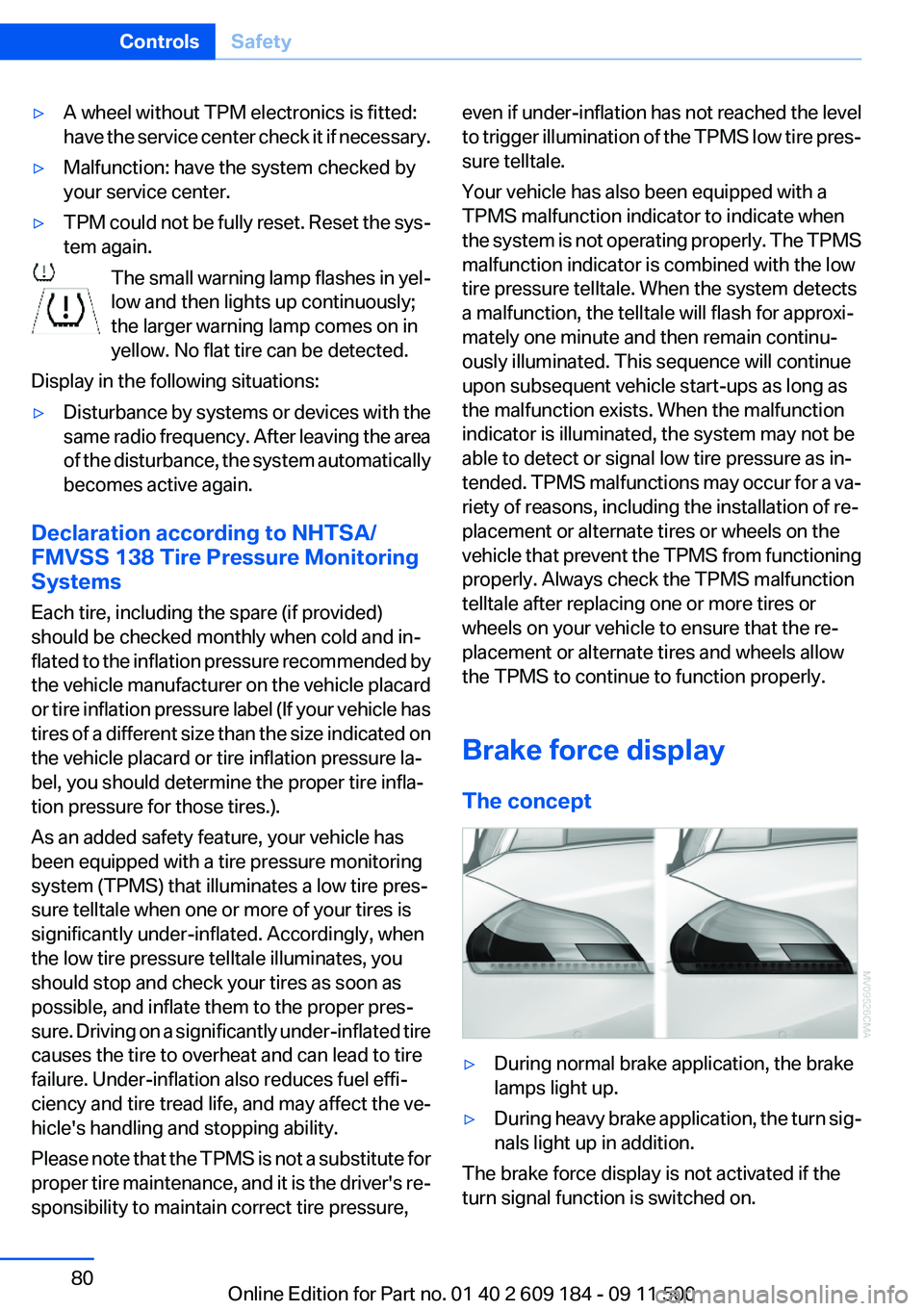
The concept‚ñ∑During normal brake application, the brake
lamps light up.‚ñ∑During heavy brake application, the turn sig‚Äê
nals light up in addition.
The brake force display is not activated if the
turn signal function is switched on.
Seite 80ControlsSafety80
Online Edition for Part no. 01 40 2 609 184 - 09 11 500
Page 160 of 220
RSC – Run-flat tires
The symbol identifying run-flat tires is a circle
with the letters RSC on the sidewall, refer to
page 161.
M+S
Winter and all-season tires.
These have better winter properties than
summer tires.
XL
Designation for specially reinforced tires.
Tire tread
Summer tires
Do not drive with a tire tread depth of less than
0.12 in/3 mm.
There is an increased danger of hydroplaning if
the tread depth is less than 0.12 in/3 mm.
Winter tires
Do not drive with a tire tread depth of less than
0.16 in/4 mm.
Below a tread depth of 0.16 in/4 mm, tires are
less suitable for winter operation.
Minimum tread depth
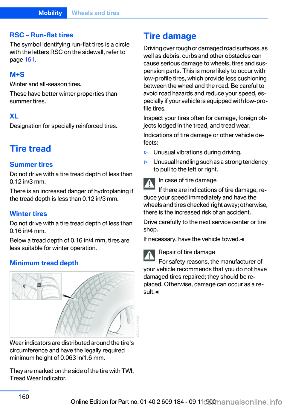
Wear indicators are distributed around the tire's
circumference and have the legally required
minimum height of 0.063 in/1.6 mm.
They are marked on the side of the tire with TWI,
Tread Wear Indicator.
Tire damage
Driving over rough or damaged road surfaces, as
well as debris, curbs and other obstacles can
cause serious damage to wheels, tires and sus‚Äê
pension parts. This is more likely to occur with
low-profile tires, which provide less cushioning
between the wheel and the road. Be careful to
avoid road hazards and reduce your speed, es‚Äê
pecially if your vehicle is equipped with low-pro‚Äê
file tires.
Inspect your tires often for damage, foreign ob‚Äê
jects lodged in the tread, and tread wear.
Indications of tire damage or other vehicle de‚Äê
fects:‚ñ∑Unusual vibrations during driving.‚ñ∑Unusual handling such as a strong tendency
to pull to the left or right.
In case of tire damage
If there are indications of tire damage, re‚Äê
duce your speed immediately and have the
wheels and tires checked right away; otherwise,
there is the increased risk of an accident.
Drive carefully to the next service center or tire
shop.
If necessary, have the vehicle towed.‚óÄ
Repair of tire damage
For safety reasons, the manufacturer of
your vehicle recommends that you do not have
damaged tires repaired; they should be re‚Äê
placed. Otherwise, damage can occur as a re‚Äê
sult.‚óÄ
Seite 160MobilityWheels and tires160
Online Edition for Part no. 01 40 2 609 184 - 09 11 500
Page 165 of 220
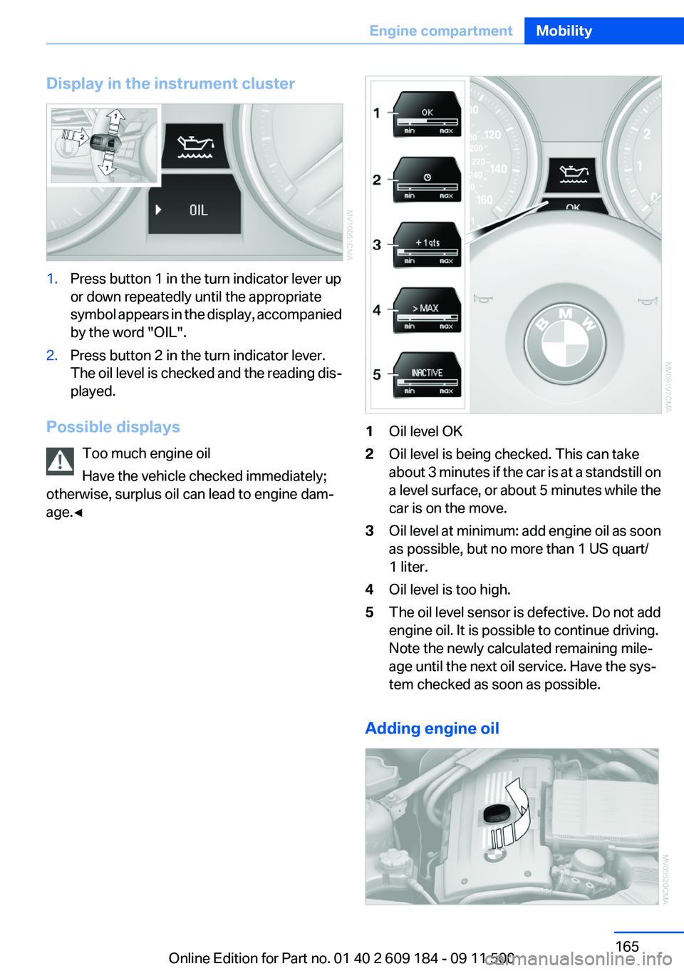
Display in the instrument cluster1.Press button 1 in the turn indicator lever up
or down repeatedly until the appropriate
symbol appears in the display, accompanied
by the word "OIL".2.Press button 2 in the turn indicator lever.
The oil level is checked and the reading dis‚Äê
played.
Possible displays
Too much engine oil
Have the vehicle checked immediately;
otherwise, surplus oil can lead to engine dam‚Äê
age.‚óÄ
1Oil level OK2Oil level is being checked. This can take
about 3 minutes if the car is at a standstill on
a level surface, or about 5 minutes while the
car is on the move.3Oil level at minimum: add engine oil as soon
as possible, but no more than 1 US quart/
1 liter.4Oil level is too high.5The oil level sensor is defective. Do not add
engine oil. It is possible to continue driving.
Note the newly calculated remaining mile‚Äê
age until the next oil service. Have the sys‚Äê
tem checked as soon as possible.
Adding engine oil
Seite 165Engine compartmentMobility165
Online Edition for Part no. 01 40 2 609 184 - 09 11 500
Page 169 of 220
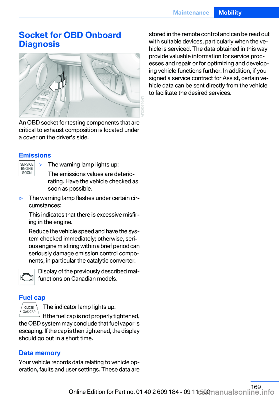
Socket for OBD Onboard
Diagnosis
An OBD socket for testing components that are
critical to exhaust composition is located under
a cover on the driver's side.
Emissions
‚ñ∑The warning lamp lights up:
The emissions values are deterio‚Äê
rating. Have the vehicle checked as
soon as possible.‚ñ∑The warning lamp flashes under certain cir‚Äê
cumstances:
This indicates that there is excessive misfir‚Äê
ing in the engine.
Reduce the vehicle speed and have the sys‚Äê
tem checked immediately; otherwise, seri‚Äê
ous engine misfiring within a brief period can
seriously damage emission control compo‚Äê
nents, in particular the catalytic converter.
Display of the previously described mal‚Äê
functions on Canadian models.
Fuel cap The indicator lamp lights up.
If the fuel cap is not properly tightened,
the OBD system may conclude that fuel vapor is
escaping. If the cap is then tightened, the display
should go out in a short time.
Data memory
Your vehicle records data relating to vehicle op‚Äê
eration, faults and user settings. These data are
stored in the remote control and can be read out
with suitable devices, particularly when the ve‚Äê
hicle is serviced. The data obtained in this way
provide valuable information for service proc‚Äê
esses and repair or for optimizing and develop‚Äê
ing vehicle functions further. In addition, if you
signed a service contract for Assist, certain ve‚Äê
hicle data can be sent directly from the vehicle
to facilitate the desired services.Seite 169MaintenanceMobility169
Online Edition for Part no. 01 40 2 609 184 - 09 11 500