power steering BUICK ENCLAVE 2010 User Guide
[x] Cancel search | Manufacturer: BUICK, Model Year: 2010, Model line: ENCLAVE, Model: BUICK ENCLAVE 2010Pages: 438, PDF Size: 2.47 MB
Page 163 of 438
Instruments and Controls 5-45
Press the customization button until
PARK TILT MIRRORS appears on
the DIC display. Press the set/reset
button once to access the settings
for this feature. Then press the
customization button to scroll
through the following settings:
OFF (default):Neither outside
mirror will be tilted down when the
vehicle is shifted into R (Reverse).
DRIVER MIRROR: The driver's
outside mirror will be tilted down
when the vehicle is shifted into
R (Reverse).
PASSENGER MIRROR: The
passenger's outside mirror will be
tilted down when the vehicle is
shifted into R (Reverse).
BOTH MIRRORS: The driver's and
passenger's outside mirrors will be
tilted down when the vehicle is
shifted into R (Reverse).
NO CHANGE: No change will be
made to this feature. The current
setting will remain. To select a setting, press the set/
reset button while the desired
setting is displayed on the DIC.
EASY EXIT SEAT
If your vehicle has this feature, it
allows you to select your preference
for the automatic easy exit seat
feature. See
Delayed Locking
on
page 2‑7for more information.
Press the customization button until
EASY EXIT SEAT appears on the
DIC display. Press the set/reset
button once to access the settings
for this feature. Then press the
customization button to scroll
through the following settings:
OFF (default): No automatic seat
exit recall will occur.
ON: The driver's seat will move
back when the key is removed from
the ignition. The steering column will
also move up and forward on
vehicles with the power tilt and
telescopic steering feature. See
Steering Wheel Adjustment
on
page 5‑2for more information. The automatic easy exit seat
movement will only occur one time
after the key is removed from the
ignition. If the automatic movement
has already occurred, and you put
the key back in the ignition and
remove it again, the seat and
steering column will stay in the
original exit position, unless a
memory recall took place prior to
removing the key again.
NO CHANGE:
No change will be
made to this feature. The current
setting will remain.
To select a setting, press the set/
reset button while the desired
setting is displayed on the DIC.
MEMORY SEAT RECALL
If your vehicle has this feature, it
allows you to select your preference
for the remote memory seat recall
feature. See Delayed Locking
on
page 2‑7for more information.
Page 164 of 438
5-46 Instruments and Controls
Press the customization button until
MEMORY SEAT RECALL appears
on the DIC display. Press the set/
reset button once to access the
settings for this feature. Then press
the customization button to scroll
through the following settings:
OFF (default):No remote memory
seat recall will occur.
ON: The driver's seat and outside
mirrors will automatically move to
the stored driving position when the
unlock button on the Remote
Keyless Entry (RKE) transmitter is
pressed. The steering column will
also move on vehicles with the
power tilt and telescopic steering
feature. See Steering Wheel
Adjustment
on page 5‑2for more
information. See “Relearn Remote
Key” under Driver Information
Center (DIC)
on page 5‑25for
more information on matching
transmitters to driver ID numbers.
NO CHANGE: No change will be
made to this feature. The current
setting will remain. To select a setting, press the set/
reset button while the desired
setting is displayed on the DIC.
REMOTE START
If your vehicle has this feature, it
allows you to turn the remote start
off or on. The remote start feature
allows you to start the engine from
outside of the vehicle using the
Remote Keyless Entry (RKE)
transmitter. See
Remote Vehicle
Start
on page 2‑5for more
information.
Press the customization button until
REMOTE START appears on the
DIC display. Press the set/reset
button once to access the settings
for this feature. Then press the
customization button to scroll
through the following settings:
OFF: The remote start feature will
be disabled.
ON (default): The remote start
feature will be enabled. NO CHANGE:
No change will be
made to this feature. The current
setting will remain.
To select a setting, press the set/
reset button while the desired
setting is displayed on the DIC.
FACTORY SETTINGS
This feature allows you to set all of
the customization features back to
their factory default settings.
Press the customization button until
FACTORY SETTINGS appears on
the DIC display. Press the set/reset
button once to access the settings
for this feature. Then press the
customization button to scroll
through the following settings:
RESTORE ALL (default): The
customization features will be set to
their factory default settings.
DO NOT RESTORE: The
customization features will not be
set to their factory default settings.
Page 171 of 438
Lighting 6-1
Lighting
Exterior Lighting
Exterior Lamp Controls . . . . . . . . 6-1
Headlamp High/Low-BeamChanger . . . . . . . . . . . . . . . . . . . . . 6-2
Flash-to-Pass . . . . . . . . . . . . . . . . . 6-3
Daytime Running Lamps (DRL)/Automatic Headlamp
System . . . . . . . . . . . . . . . . . . . . . . 6-3
Delayed Headlamps . . . . . . . . . . 6-3
Adaptive Forward Lighting (AFL) . . . . . . . . . . . . . . . 6-4
Hazard Warning Flashers . . . . . 6-4
Turn and Lane-Change Signals . . . . . . . . . . . . . . . . . . . . . . 6-4
Fog Lamps . . . . . . . . . . . . . . . . . . . . 6-5
Interior Lighting
Instrument Panel Illumination Control . . . . . . . . . . . . . . . . . . . . . . 6-5
Dome Lamps . . . . . . . . . . . . . . . . . 6-5
Reading Lamps . . . . . . . . . . . . . . . 6-5
Lighting Features
Entry Lighting . . . . . . . . . . . . . . . . . 6-6
Delayed Entry Lighting . . . . . . . . 6-6
Delayed Exit Lighting . . . . . . . . . 6-6
Parade Dimming . . . . . . . . . . . . . . 6-7
Battery Load Management . . . . 6-7
Battery Power Protection . . . . . . 6-8
Exterior Lighting
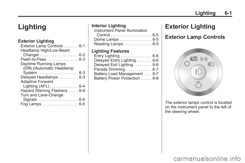
Exterior Lamp Controls
The exterior lamps control is located
on the instrument panel to the left of
the steering wheel.
Page 243 of 438
Driving and Operating 9-1
Driving and
Operating
Driving Information
Defensive Driving . . . . . . . . . . . . . 9-2
Drunk Driving . . . . . . . . . . . . . . . . . 9-2
Control of a Vehicle . . . . . . . . . . . 9-3
Braking . . . . . . . . . . . . . . . . . . . . . . . 9-3
Steering . . . . . . . . . . . . . . . . . . . . . . . 9-4
Off-Road Recovery . . . . . . . . . . . . 9-5
Loss of Control . . . . . . . . . . . . . . . . 9-5
Driving on Wet Roads . . . . . . . . . 9-6
Highway Hypnosis . . . . . . . . . . . . 9-7
Hill and Mountain Roads . . . . . . 9-8
Winter Driving . . . . . . . . . . . . . . . . . 9-9
If the Vehicle is Stuck . . . . . . . . 9-11
Vehicle Load Limits . . . . . . . . . . 9-12
Starting and Operating
New Vehicle Break-In . . . . . . . . 9-16
Ignition Positions . . . . . . . . . . . . 9-16
Retained AccessoryPower (RAP) . . . . . . . . . . . . . . . 9-17
Starting the Engine . . . . . . . . . . 9-18
Engine Heater . . . . . . . . . . . . . . . 9-19 Shifting Into Park . . . . . . . . . . . . 9-20
Shifting Out of Park . . . . . . . . . . 9-21
Parking Over Things
That Burn . . . . . . . . . . . . . . . . . . 9-21
Engine Exhaust
Engine Exhaust . . . . . . . . . . . . . . 9-22
Running the Vehicle WhileParked . . . . . . . . . . . . . . . . . . . . . 9-22
Automatic Transmission
Automatic Transmission . . . . . 9-23
Manual Mode . . . . . . . . . . . . . . . . 9-25
Tow/Haul Mode . . . . . . . . . . . . . . 9-25
Drive Systems
All-Wheel Drive . . . . . . . . . . . . . . 9-26
Brakes
Antilock BrakeSystem (ABS) . . . . . . . . . . . . . . 9-26
Parking Brake . . . . . . . . . . . . . . . 9-27
Brake Assist . . . . . . . . . . . . . . . . . 9-28
Ride Control Systems
StabiliTrak System . . . . . . . . . . . 9-28
Cruise Control
Cruise Control . . . . . . . . . . . . . . . 9-30
Object Detection Systems
Ultrasonic Parking Assist . . . . 9-33
Rear Vision Camera (RVC) . . . . . . . . . . . . . 9-34
Fuel
Fuel . . . . . . . . . . . . . . . . . . . . . . . . . 9-39
Recommended Fuel . . . . . . . . . 9-40
Gasoline Specifications . . . . . . 9-40
California FuelRequirements . . . . . . . . . . . . . . 9-40
Fuels in Foreign Countries . . . 9-40
Fuel Additives . . . . . . . . . . . . . . . 9-41
Filling the Tank . . . . . . . . . . . . . . 9-42
Filling a Portable Fuel Container . . . . . . . . . . . . . . . . . . . 9-44
Towing
General TowingInformation . . . . . . . . . . . . . . . . . 9-44
Driving Characteristics and Towing Tips . . . . . . . . . . . . . . . . 9-45
Trailer Towing . . . . . . . . . . . . . . . . 9-50
Towing Equipment . . . . . . . . . . . 9-53
Conversions and Add-Ons
Add-On Electrical Equipment . . . . . . . . . . . . . . . . . 9-55
Page 246 of 438
9-4 Driving and Operating
If the engine ever stops while the
vehicle is being driven, brake
normally but do not pump the
brakes. If the brakes are pumped,
the pedal could get harder to push
down. If the engine stops, there will
still be some power brake assist but
it will be used when the brake is
applied. Once the power assist is
used up, it can take longer to stop
and the brake pedal will be harder
to push.
Adding non-dealer/non-retailer
accessories can affect vehicle
performance. SeeAccessories and
Modifications on page 10‑3.
Steering
Power Steering
If power steering assist is lost
because the engine stops or the
power steering system is not
functioning, the vehicle can be
steered but it will take more effort.
Variable Effort Steering
The vehicle has a steering system
that continuously adjusts the effort
felt when steering at all vehicle
speeds. It provides ease when
parking, yet a firm, solid feel at
highway speeds.
Steering Tips
It is important to take curves at a
reasonable speed.
Traction in a curve depends on the
condition of the tires and the road
surface, the angle at which the
curve is banked, and vehicle speed.
While in a curve, speed is the one
factor that can be controlled.
If there is a need to reduce speed,
do it before entering the curve, while
the front wheels are straight.
Try to adjust the speed so you can
drive through the curve. Maintain a
reasonable, steady speed. Wait to
accelerate until out of the curve, and
then accelerate gently into the
straightaway.
Steering in Emergencies
There are times when steering can
be more effective than braking. For
example, you come over a hill and
find a truck stopped in your lane,
or a car suddenly pulls out from
nowhere, or a child darts out from
between parked cars and stops right
in front of you. These problems can
be avoided by braking —if you can
stop in time. But sometimes you
cannot stop in time because there is
no room. That is the time for
evasive action —steering around
the problem.
The vehicle can perform very well in
emergencies like these. First apply
the brakes. See Braking
on
page 9‑3. It is better to remove as
much speed as possible from a
collision. Then steer around the
problem, to the left or right
depending on the space available.
Page 259 of 438
Driving and Operating 9-17
Notice:Using a tool to force the
key to turn in the ignition could
cause damage to the switch or
break the key. Use the correct
key, make sure it is all the way in,
and turn it only with your hand.
If the key cannot be turned by
hand, see your dealer/retailer.
((LOCK/OFF): This position locks
the ignition and transmission. The
key can be removed in LOCK/OFF.
The shift lever must be in P (Park)
to turn the ignition switch to
LOCK/OFF.
The steering can bind with the
wheels turned off center. If this
happens, move the steering wheel
from right to left while turning the
key to ACC/ACCESSORY. If this
doesn't work, then the vehicle needs
service.
ACC (ACC/ACCESSORY): This is
the position in which you can
operate the electrical accessories or
items plugged into the accessory power outlets. This position unlocks
the ignition and steering wheel.
Use this position if the vehicle must
be pushed or towed.
R(ON/RUN):
This position can be
used to operate the electrical
accessories and to display some
instrument panel warning and
indicator lights. The switch stays in
this position when the engine is
running. The transmission is also
unlocked in this position. If you
leave the key in the ACC/
ACCESSORY or ON/RUN position
with the engine off, the battery could
be drained. You may not be able to
start the vehicle if the battery is
allowed to drain for an extended
period of time.
/(START): This is the position
that starts the engine. When the
engine starts, release the key. The
ignition switch will return to ON/RUN
for driving.
Retained Accessory
Power (RAP)
These vehicle accessories can be
used for up to 10 minutes after the
ignition key is turned off:
.Audio System
.Power Windows
.Sunroof (if equipped)
Power to the windows and sunroof
will work up to 10 minutes or until a
door is opened.
The radio continues to work for
10 minutes or until the driver's door
is opened.
For an additional 10 minutes of
operation, close all the doors and
turn the key to ON/RUN and then
back to LOCK/OFF.
All these features will work when
the key is in the ON/RUN or
ACC/ACCESSORY positions.
Page 297 of 438

Driving and Operating 9-55
They should be connected by your
dealer/retailer or a qualified service
center.
If the back-up lamp circuit is not
functional, contact your dealer/
retailer.
If a remote (non-vehicle) battery is
being charged, press the Tow/Haul
mode switch located on the center
console near the climate controls.
This will boost the vehicle system
voltage and properly charge the
battery. If the trailer is too light for
Tow/Haul mode, turn on the
headlamps (Non-HID only) as a
second way to boost the vehicle
system and charge the battery.Electric Trailer Brake Control
Wiring Provisions
These wiring provisions for an
electric trailer brake controller are
included with the vehicle as part of
the trailer wiring package. The
instrument panel contains blunt cut
wires behind the steering column for
the electric trailer brake controller.
The harness contains the following
wires:
.Red/Black: Power Supply
.White: Brake Switch Signal
.Gray: Illumination
.Dark Blue: Trailer Brake Signal
.Black: Ground
The electric trailer brake controller
should be installed by your dealer/
retailer or a qualified service center.
Conversions and
Add-Ons
Add-On Electrical
Equipment
Notice: Do not add anything
electrical to the vehicle unless
you check with your dealer/
retailer first. Some electrical
equipment can damage the
vehicle and the damage would
not be covered by the vehicle's
warranty. Some add-on electrical
equipment can keep other
components from working as
they should.
Add-on equipment can drain the
vehicle battery, even if the vehicle is
not operating.
The vehicle has an airbag system.
Before attempting to add anything
electrical to the vehicle, see
Servicing the Airbag-Equipped
Vehicle
on page 3‑41and Adding
Equipment to the Airbag-Equipped
Vehicle on page 3‑42.
Page 299 of 438
Vehicle Care 10-1
Vehicle Care
General Information
General Information . . . . . . . . . . 10-2
California Proposition65 Warning . . . . . . . . . . . . . . . . . 10-3
California Perchlorate Materials Requirements . . . . 10-3
Accessories and Modifications . . . . . . . . . . . . . . . 10-3
Vehicle Checks
Doing Your OwnService Work . . . . . . . . . . . . . . . 10-4
Hood . . . . . . . . . . . . . . . . . . . . . . . . 10-4
Engine Compartment Overview . . . . . . . . . . . . . . . . . . . 10-6
Engine Cover . . . . . . . . . . . . . . . . 10-7
Engine Oil . . . . . . . . . . . . . . . . . . . 10-8
Engine Oil Life System . . . . . 10-10
Automatic Transmission Fluid . . . . . . . . . . . . . . . . . . . . . . 10-11
Engine Air Cleaner/Filter . . . . 10-12
Cooling System . . . . . . . . . . . . 10-14
Engine Coolant . . . . . . . . . . . . . 10-14
Engine Overheating . . . . . . . . 10-18 Overheated Engine
Protection
Operating Mode . . . . . . . . . . . 10-20
Power Steering Fluid . . . . . . . 10-20
Washer Fluid . . . . . . . . . . . . . . . 10-21
Brakes . . . . . . . . . . . . . . . . . . . . . 10-22
Brake Fluid . . . . . . . . . . . . . . . . . 10-23
Battery . . . . . . . . . . . . . . . . . . . . . 10-25
All-Wheel Drive . . . . . . . . . . . . . 10-25
Starter Switch Check . . . . . . . 10-25
Automatic Transmission Shift Lock Control System
Check . . . . . . . . . . . . . . . . . . . . . 10-26
Ignition Transmission Lock Check . . . . . . . . . . . . . . . . . . . . . 10-26
Park Brake and P (Park) Mechanism Check . . . . . . . . 10-26
Wiper Blade Replacement . . . . . . . . . . . . . . 10-27
Windshield Replacement . . . 10-28
Headlamp Aiming
Headlamp Aiming . . . . . . . . . . 10-28
Bulb Replacement
Bulb Replacement . . . . . . . . . . 10-28
Halogen Bulbs . . . . . . . . . . . . . . 10-28
High Intensity Discharge (HID) Lighting . . . . . . . . . . . . . 10-29 Taillamps, Turn Signal,
Sidemarker, and
Stoplamps . . . . . . . . . . . . . . . . 10-29
License Plate Lamp . . . . . . . . 10-30
Replacement Bulbs . . . . . . . . . 10-30
Electrical System
High Voltage Devices and Wiring . . . . . . . . . . . . . . . . . . . . . 10-30
Electrical System Overload . . . . . . . . . . . . . . . . . . 10-31
Fuses and Circuit Breakers . . . . . . . . . . . . . . . . . . 10-31
Engine Compartment Fuse Block . . . . . . . . . . . . . . . . . . . . . 10-31
Instrument Panel Fuse Block . . . . . . . . . . . . . . . . . . . . . 10-35
Wheels and Tires
Tires . . . . . . . . . . . . . . . . . . . . . . . . 10-37
Tire Sidewall Labeling . . . . . . 10-38
Tire Designations . . . . . . . . . . . 10-40
Tire Terminology and
Definitions . . . . . . . . . . . . . . . . 10-41
Tire Pressure . . . . . . . . . . . . . . . 10-44
Tire Pressure Monitor System . . . . . . . . . . . . . . . . . . . 10-45
Tire Pressure Monitor Operation . . . . . . . . . . . . . . . . . 10-46
Page 305 of 438
Vehicle Care 10-7
A. Radiator Pressure Cap. SeeCooling System on page 10‑14.
B. Engine Coolant Recovery Cap. See Cooling System
on
page 10‑14.
C. Remote Negative (−) Terminal. See Jump Starting
on
page 10‑81.
D. Engine Compartment Fuse
Block on page 10‑31.
E. Remote Positive (+) Terminal. See Jump Starting
on
page 10‑81.
F. Power Steering Reservoir and Cap (under engine cover). See
Power Steering Fluid
on
page 10‑20.
G. Engine Oil Fill Cap. See “When
to Add Engine Oil” underEngine
Oil on page 10‑8. H.
Engine Cover on page 10‑7.
I. Engine Oil Dipstick. See “Checking Engine Oil” under
Engine Oil on page 10‑8.
J. Automatic Transmission Fluid Dipstick. See “Checking the
Fluid Level” underAutomatic
Transmission Fluid
on
page 10‑11.
K. Brake Master Cylinder Reservoir. See “Brake Fluid”
under Brakes on page 10‑22.
L. Engine Air Cleaner/Filter
on
page 10‑12.
M. Windshield Washer Fluid Reservoir. See “Adding Washer
Fluid” under Washer Fluid
on
page 10‑21.
Engine Cover
A. Oil Fill Cap
B. Engine Cover
To remove:
1. Remove the oil fill cap (A).
2. Raise the engine cover (B) to release from the retainers.
3. Lift and remove the engine cover.
4. Reverse Steps 1 through 3 to reinstall engine cover.
Page 318 of 438
10-20 Vehicle Care
If the overheat warning is displayed
with no sign of steam:
1. Turn the air conditioning off.
2. Turn the heater on to the highesttemperature and to the highest
fan speed. Open the windows as
necessary.
3. If in a traffic jam, shift to N (Neutral), otherwise, shift to
the highest gear while
driving —D (Drive) or L (Low).
If the temperature overheat gage is
no longer in the overheat zone or an
overheat warning no longer
displays, the vehicle can be driven.
Continue to drive the vehicle slow
for about 10 minutes. Keep a safe
vehicle distance from the car in front
of you. If the warning does not come
back on, continue to drive normally.
If the warning continues, pull over,
stop, and park the vehicle
right away. If there is no sign of steam, idle the
engine for three minutes while
parked. If the warning is still
displayed, turn off the engine until it
cools down. Also, see
“Overheated
Engine Protection Operating Mode”
next in this section.
Overheated Engine
Protection
Operating Mode
This emergency operating mode lets
the vehicle be driven to a safe place
in an emergency situation. If an
overheated engine condition exists,
an overheat protection mode which
alternates firing groups of cylinders
helps prevent engine damage. In
this mode, there is a significant loss
in power and engine performance.
The temperature gage indicates an
overheat condition exists. Driving
extended distances and/or towing a
trailer in the overheat protection
mode should be avoided. Notice:
After driving in the
overheated engine protection
operating mode, to avoid engine
damage, allow the engine to cool
before attempting any repair. The
engine oil will be severely
degraded. Repair the cause of
coolant loss, change the oil and
reset the oil life system. See
Engine Oil on page 10‑8.
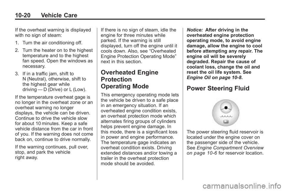
Power Steering Fluid
The power steering fluid reservoir is
located under the engine cover on
the passenger side of the vehicle.
See Engine Compartment Overview
on page 10‑6for reservoir location.