ECO mode BUICK ENVISION 2019 Owner's Manual
[x] Cancel search | Manufacturer: BUICK, Model Year: 2019, Model line: ENVISION, Model: BUICK ENVISION 2019Pages: 377, PDF Size: 6.03 MB
Page 33 of 377
Buick Envision Owner Manual (GMNA-Localizing-U.S./Canada/Mexico-
12032235) - 2019 - CRC - 6/27/18
32 Keys, Doors, and Windows
3. Insert the vehicle key of thenew transmitter into the key
lock cylinder on the outside of
the driver door and turn the key
to the unlock position five times
within 10 seconds.
The DIC displays READY FOR
REMOTE #2, 3, 4, or 5.
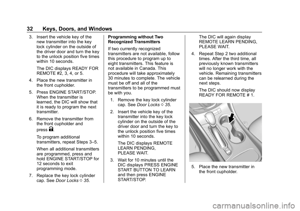
4. Place the new transmitter in the front cupholder.
5. Press ENGINE START/STOP. When the transmitter is
learned, the DIC will show that
it is ready to program the next
transmitter.
6. Remove the transmitter from the front cupholder and
press
K.
To program additional
transmitters, repeat Steps 3–5.
When all additional transmitters
are programmed, press and
hold ENGINE START/STOP for
12 seconds to exit
programming mode.
7. Replace the key lock cylinder cap. See Door Locks 035. Programming without Two
Recognized Transmitters
If two currently recognized
transmitters are not available, follow
this procedure to program up to
eight transmitters. This feature is
not available in Canada. This
procedure will take approximately
30 minutes to complete. The vehicle
must be off and all of the
transmitters to be programmed must
be with you.
1. Remove the key lock cylinder cap. See Door Locks 035.
2. Insert the vehicle key of the transmitter into the key lock
cylinder on the outside of the
driver door and turn the key to
the unlock position five times
within 10 seconds.
The DIC displays REMOTE
LEARN PENDING,
PLEASE WAIT.
3. Wait for 10 minutes until the DIC displays PRESS ENGINE
START BUTTON TO LEARN
and then press ENGINE
START/STOP. The DIC will again display
REMOTE LEARN PENDING,
PLEASE WAIT.
4. Repeat Step 2 two additional times. After the third time, all
previously known transmitters
will no longer work with the
vehicle. Remaining transmitters
can be relearned during the
next steps.
The DIC should now display
READY FOR REMOTE # 1.
5. Place the new transmitter inthe front cupholder.
Page 34 of 377
Buick Envision Owner Manual (GMNA-Localizing-U.S./Canada/Mexico-
12032235) - 2019 - CRC - 6/27/18
Keys, Doors, and Windows 33
6. Press ENGINE START/STOP.When the transmitter is
learned, the DIC will show that
it is ready to program the next
transmitter.
7. Remove the transmitter from the cupholder and press
K.
To program additional
transmitters, repeat Steps 4–6.
When all additional transmitters
are programmed, press and
hold ENGINE START/STOP for
12 seconds to exit
programming mode.
8. Replace the key lock cylinder cap. See Door Locks 035.
Starting the Vehicle with a Low
Transmitter Battery
If the transmitter battery is weak or if
there is interference with the signal,
the DIC may display NO REMOTE
DETECTED or NO REMOTE KEY
WAS DETECTED PLACE KEY IN
TRANSMITTER POCKET THEN
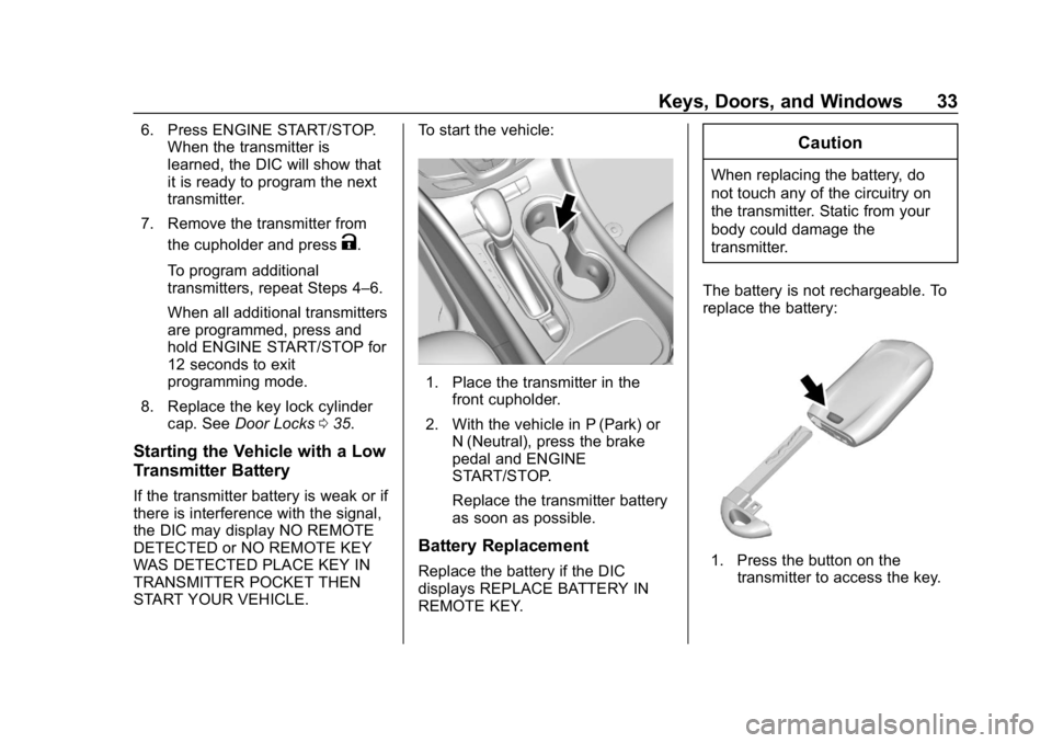
START YOUR VEHICLE. To start the vehicle:
1. Place the transmitter in the
front cupholder.
2. With the vehicle in P (Park) or N (Neutral), press the brake
pedal and ENGINE
START/STOP.
Replace the transmitter battery
as soon as possible.
Battery Replacement
Replace the battery if the DIC
displays REPLACE BATTERY IN
REMOTE KEY.
Caution
When replacing the battery, do
not touch any of the circuitry on
the transmitter. Static from your
body could damage the
transmitter.
The battery is not rechargeable. To
replace the battery:
1. Press the button on the transmitter to access the key.
Page 43 of 377
Buick Envision Owner Manual (GMNA-Localizing-U.S./Canada/Mexico-
12032235) - 2019 - CRC - 6/27/18
42 Keys, Doors, and Windows
Caution
Manually forcing the liftgate to
open or close during a power
cycle can damage the vehicle.
Allow the power cycle to
complete.
The power liftgate may be
temporarily disabled under extreme
low temperatures, or after repeated
power cycling over a short period of
time. If this occurs, the liftgate can
still be operated manually.
If the vehicle is shifted out of
P (Park) while the power function is
in progress, the liftgate will continue
to completion. If the vehicle is
accelerated before the liftgate has
completed moving, the liftgate may
stop or reverse direction. Check for
DIC messages and make sure the
liftgate is closed and latched before
driving. Falling Liftgate Detection
If the power liftgate automatically
closes after a power opening cycle,
it indicates that the system is
reacting to excess weight on the
liftgate or a possible support strut
failure. Remove any excess weight.
If the liftgate continues to
automatically close after opening,
see your dealer for service before
using the power liftgate. Interfering
with the power liftgate motion or
manually closing the liftgate too
quickly after power opening may
resemble a support strut failure.
This could also activate the falling
liftgate detection feature. Allow the
liftgate to complete its operation and
wait a few seconds before manually
closing the liftgate.
Obstacle Detection Features
If the liftgate encounters an obstacle
during a power open or close cycle,
a warning chime will sound and the
liftgate will automatically reverse
direction and move a short distance
away from the obstacle. After
removing the obstruction, the powerliftgate operation can be used again.
If the liftgate encounters multiple
obstacles on the same power cycle,
the power function will deactivate.
After removing the obstructions,
manually close the liftgate which will
allow normal power operation
functions to resume.
If the vehicle is locked while the
liftgate is closing, and an obstacle is
encountered that prevents the
liftgate from completely closing, the
horn will sound as an alert that the
liftgate did not close.
Pinch sensors are on the side
edges of the liftgate. If an object is
caught between the liftgate and the
vehicle and presses against this
sensor, the liftgate will reverse
direction and open fully. The liftgate
will remain open until it is activated
again or closed manually.Setting the 3/4 Mode
To change the position the liftgate
stops at when opening:
1. Select MAX or 3/4 mode and power open the liftgate.
Page 44 of 377

Buick Envision Owner Manual (GMNA-Localizing-U.S./Canada/Mexico-
12032235) - 2019 - CRC - 6/27/18
Keys, Doors, and Windows 43
2. Stop the liftgate movement atthe desired height by pressing
any liftgate switch. Manually
adjust the liftgate position if
needed.
3. Press and hold
8next to the
pull cup on the outside of the
liftgate until the turn signals
flash and a beep sounds. This
indicates the setting has been
recorded.
The liftgate cannot be set below a
minimum programmable height.
If there is no light flash or sound,
then the height adjustment may be
too low.
Manual Operation
Select OFF to manually operate the
liftgate. See “Manual Liftgate” at the
beginning of this section.
Caution
Attempting to move the liftgate
too quickly and with excessive
force may result in damage to the
vehicle. Operate the liftgate manually with a
smooth motion and moderate
speed. The system includes a
feature which limits the manual
closing speed to protect the
components.
Hands-Free Operation
If equipped, the liftgate may be
operated with a kicking motion
under the rear bumper.
The liftgate will not operate if the
RKE transmitter is not within
1 m (3 ft).
The hands-free feature will not work
while the liftgate is moving. To stop
the liftgate while in motion use one
of the liftgate switches.
The hands-free feature can be
customized. See
Vehicle
Personalization 0150. Choose from
the following:
On-Open and Close : The kicking
motion is activated to both open and
close the liftgate.
On-Open Only : The kicking motion
is activated to only open the liftgate. Off :
The feature is disabled.
Length of Kick Zone
Page 79 of 377
Buick Envision Owner Manual (GMNA-Localizing-U.S./Canada/Mexico-
12032235) - 2019 - CRC - 6/27/18
78 Seats and Restraints
The passenger seat position sensor
and the passenger seat belt buckle
also provide information that is used
to determine if the passenger knee
airbag should inflate.
Seat-mounted side impact airbags
are designed to inflate in moderate
to severe side crashes depending
on the location of the impact.
Seat-mounted side impact airbags
are not designed to inflate in frontal
impacts, near frontal impacts,
rollovers, or rear impacts.
A seat-mounted side impact airbag
is designed to inflate on the side of
the vehicle that is struck.
Roof-rail airbags are designed to
inflate in moderate to severe side
crashes depending on the location
of the impact. In addition, these
roof-rail airbags are designed to
inflate during a rollover or in a
severe frontal impact. Roof-rail
airbags are not designed to inflate in
rear impacts. Both roof-rail airbags
will inflate when either side of the
vehicle is struck, if the sensingsystem predicts that the vehicle is
about to roll over on its side, or in a
severe frontal impact.
In any particular crash, no one can
say whether an airbag should have
inflated simply because of the
vehicle damage or the repair costs.
What Makes an Airbag
Inflate?
In a deployment event, the sensing
system sends an electrical signal
triggering a release of gas from the
inflator. Gas from the inflator fills the
airbag causing the bag to break out
of the cover. The inflator, the airbag,
and related hardware are all part of
the airbag module.
For airbag locations, see
Where Are
the Airbags? 075.
How Does an Airbag
Restrain?
In moderate to severe frontal or
near frontal collisions, even belted
occupants can contact the steering
wheel or the instrument panel. In moderate to severe side collisions,
even belted occupants can contact
the inside of the vehicle.
Airbags supplement the protection
provided by seat belts by
distributing the force of the impact
more evenly over the
occupant's body.
Rollover capable roof-rail airbags
are designed to help contain the
head and chest of occupants in the
outboard seating positions in the
first and second rows. The rollover
capable roof-rail airbags are
designed to help reduce the risk of
full or partial ejection in rollover
events, although no system can
prevent all such ejections.
But airbags would not help in many
types of collisions, primarily
because the occupant's motion is
not toward those airbags. See
When
Should an Airbag Inflate? 077.
Airbags should never be regarded
as anything more than a supplement
to seat belts.
Page 133 of 377
Buick Envision Owner Manual (GMNA-Localizing-U.S./Canada/Mexico-
12032235) - 2019 - CRC - 6/27/18
132 Instruments and Controls
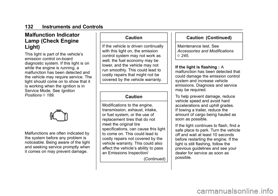
Malfunction Indicator
Lamp (Check Engine
Light)
This light is part of the vehicle’s
emission control on-board
diagnostic system. If this light is on
while the engine is running, a
malfunction has been detected and
the vehicle may require service. The
light should come on to show that it
is working when the ignition is in
Service Mode. SeeIgnition
Positions 0189.
Malfunctions are often indicated by
the system before any problem is
noticeable. Being aware of the light
and seeking service promptly when
it comes on may prevent damage.
Caution
If the vehicle is driven continually
with this light on, the emission
control system may not work as
well, the fuel economy may be
lower, and the vehicle may not
run smoothly. This could lead to
costly repairs that might not be
covered by the vehicle warranty.
Caution
Modifications to the engine,
transmission, exhaust, intake,
or fuel system, or the use of
replacement tires that do not
meet the original tire
specifications, can cause this light
to come on. This could lead to
costly repairs not covered by the
vehicle warranty. This could also
affect the vehicle’s ability to pass
an Emissions Inspection/
(Continued)
Caution (Continued)
Maintenance test. See
Accessories and Modifications
0245.
If the light is flashing : A
malfunction has been detected that
could damage the emission control
system and increase vehicle
emissions. Diagnosis and service
may be required.
To help prevent damage, reduce
vehicle speed and avoid hard
accelerations and uphill grades.
If towing a trailer, reduce the
amount of cargo being hauled as
soon as possible.
If the light continues to flash, find a
safe place to park. Turn the vehicle
off and wait at least 10 seconds
before restarting the engine. If the
light is still flashing, follow the
previous guidelines and see your
dealer for service as soon as
possible.
Page 134 of 377
Buick Envision Owner Manual (GMNA-Localizing-U.S./Canada/Mexico-
12032235) - 2019 - CRC - 6/27/18
Instruments and Controls 133
If the light is on steady :A
malfunction has been detected.
Diagnosis and service may be
required.
Check the following:
. If fuel has been added to the
vehicle using the capless fuel
funnel adapter, make sure that it
has been removed. See “Filling
the Tank with a Portable Gas
Can” under Filling the Tank
0 232. The diagnostic system
can detect if the adapter has
been left installed in the vehicle,
allowing fuel to evaporate into
the atmosphere. A few driving
trips with the adapter removed
may turn off the light.
. Poor fuel quality can cause
inefficient engine operation and
poor driveability, which may go
away once the engine is warmed
up. If this occurs, change the
fuel brand. It may require at
least one full tank of the proper
fuel to turn the light off.
See Recommended Fuel (2.5L
Engine) 0230 orRecommended
Fuel (2.0L Engine) 0230. If the light remains on, see your
dealer.
Emissions Inspection and
Maintenance Programs
If the vehicle requires an Emissions
Inspection/Maintenance test, the
test equipment will likely connect to
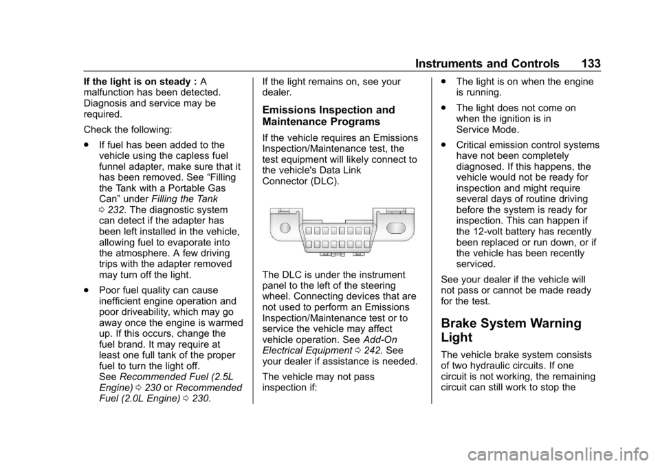
the vehicle's Data Link
Connector (DLC).
The DLC is under the instrument
panel to the left of the steering
wheel. Connecting devices that are
not used to perform an Emissions
Inspection/Maintenance test or to
service the vehicle may affect
vehicle operation. See
Add-On
Electrical Equipment 0242. See
your dealer if assistance is needed.
The vehicle may not pass
inspection if: .
The light is on when the engine
is running.
. The light does not come on
when the ignition is in
Service Mode.
. Critical emission control systems
have not been completely
diagnosed. If this happens, the
vehicle would not be ready for
inspection and might require
several days of routine driving
before the system is ready for
inspection. This can happen if
the 12-volt battery has recently
been replaced or run down, or if
the vehicle has been recently
serviced.
See your dealer if the vehicle will
not pass or cannot be made ready
for the test.
Brake System Warning
Light
The vehicle brake system consists
of two hydraulic circuits. If one
circuit is not working, the remaining
circuit can still work to stop the
Page 170 of 377
Buick Envision Owner Manual (GMNA-Localizing-U.S./Canada/Mexico-
12032235) - 2019 - CRC - 6/27/18
Climate Controls 169
Climate Controls
Climate Control Systems
Dual Automatic ClimateControl System . . . . . . . . . . . . . 169
Rear Climate Control System . . . . . . . . . . . . . . . . . . . . . . 172
Air Vents
Air Vents . . . . . . . . . . . . . . . . . . . . . 174
Maintenance
Passenger Compartment AirFilter . . . . . . . . . . . . . . . . . . . . . . . . 174
Service . . . . . . . . . . . . . . . . . . . . . . . 175
Climate Control Systems
Dual Automatic Climate Control System
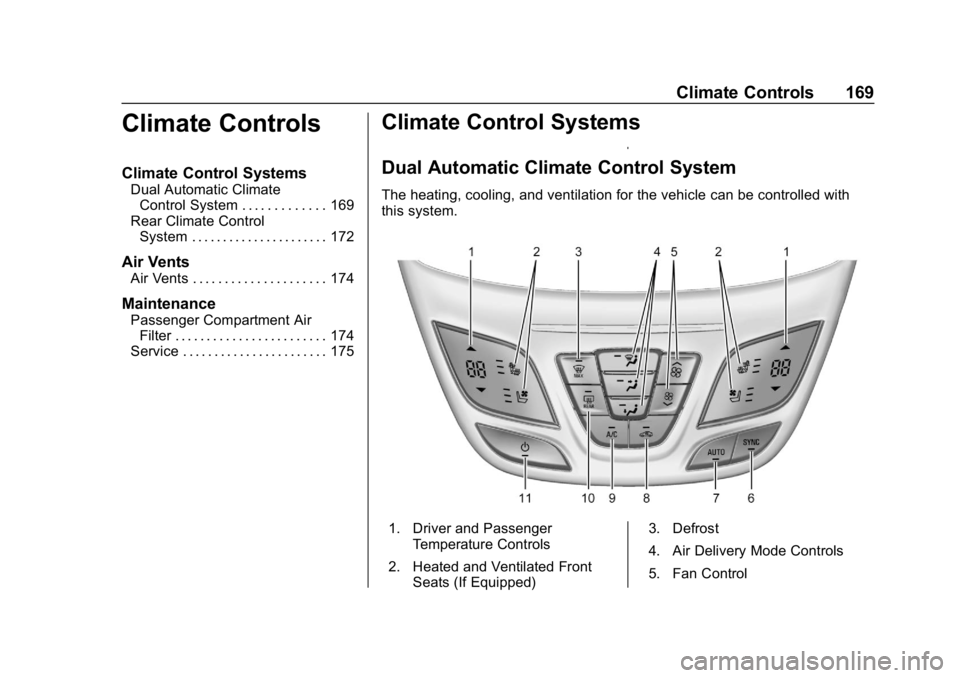
The heating, cooling, and ventilation for the vehicle can be controlled with
this system.
1. Driver and Passenger
Temperature Controls
2. Heated and Ventilated Front Seats (If Equipped) 3. Defrost
4. Air Delivery Mode Controls
5. Fan Control
Page 177 of 377

Buick Envision Owner Manual (GMNA-Localizing-U.S./Canada/Mexico-
12032235) - 2019 - CRC - 6/27/18
176 Driving and Operating
Driving and
Operating
Driving Information
Driver Behavior . . . . . . . . . . . . . . . 177
Driving Environment . . . . . . . . . . 177
Vehicle Design . . . . . . . . . . . . . . . 177
Distracted Driving . . . . . . . . . . . . 178
Defensive Driving . . . . . . . . . . . . . 178
Drunk Driving . . . . . . . . . . . . . . . . . 179
Control of a Vehicle . . . . . . . . . . . 179
Braking . . . . . . . . . . . . . . . . . . . . . . . 179
Steering . . . . . . . . . . . . . . . . . . . . . . 179
Off-Road Recovery . . . . . . . . . . . 180
Loss of Control . . . . . . . . . . . . . . . 180
Driving on Wet Roads . . . . . . . . 181
Hill and Mountain Roads . . . . . 182
Winter Driving . . . . . . . . . . . . . . . . 182
If the Vehicle Is Stuck . . . . . . . . 184
Vehicle Load Limits . . . . . . . . . . . 184
Starting and Operating
New Vehicle Break-In . . . . . . . . . 188
Ignition Positions . . . . . . . . . . . . . 189
Starting the Engine . . . . . . . . . . . 191
Stop/Start System . . . . . . . . . . . . 191
Engine Heater . . . . . . . . . . . . . . . . 193Retained Accessory
Power (RAP) . . . . . . . . . . . . . . . . 194
Shifting Into Park . . . . . . . . . . . . . 194
Shifting out of Park . . . . . . . . . . . 195
Parking over Things That Burn . . . . . . . . . . . . . . . . . . . 195
Extended Parking . . . . . . . . . . . . 196
Engine Exhaust
Engine Exhaust . . . . . . . . . . . . . . 196
Running the Vehicle While Parked . . . . . . . . . . . . . . . . . . . . . . 197
Automatic Transmission
Automatic Transmission . . . . . . 197
Manual Mode . . . . . . . . . . . . . . . . . 199
Drive Systems
All-Wheel Drive . . . . . . . . . . . . . . . 200
Brakes
Antilock BrakeSystem (ABS) . . . . . . . . . . . . . . . 200
Electric Parking Brake . . . . . . . . 201
Brake Assist . . . . . . . . . . . . . . . . . . 203
Hill Start Assist (HSA) . . . . . . . . 203
Ride Control Systems
Traction Control/Electronic Stability Control . . . . . . . . . . . . . 203
Cruise Control
Cruise Control . . . . . . . . . . . . . . . . 205
Adaptive Cruise Control . . . . . . 208
Driver Assistance Systems
Driver Assistance Systems . . . 215
Assistance Systems forParking or Backing . . . . . . . . . . 217
Assistance Systems for Driving . . . . . . . . . . . . . . . . . . . . . . 222
Forward Collision Alert (FCA) System . . . . . . . . . . . . . . . . . . . . . . 222
Forward Automatic Braking (FAB) . . . . . . . . . . . . . . . 224
Side Blind Zone Alert (SBZA) . . . . . . . . . . . . . . . . 226
Lane Change Alert (LCA) . . . . . 226
Lane Departure Warning (LDW) . . . . . . . . . . . . . 228
Lane Keep Assist (LKA) . . . . . . 228
Fuel
Top Tier Fuel . . . . . . . . . . . . . . . . . 230
Recommended Fuel (2.5L Engine) . . . . . . . . . . . . . . . . . . . . . 230
Recommended Fuel (2.0L Engine) . . . . . . . . . . . . . . . . . . . . . 230
Prohibited Fuels . . . . . . . . . . . . . . 231
Fuels in Foreign Countries . . . 231
Fuel Additives . . . . . . . . . . . . . . . . 231
Filling the Tank . . . . . . . . . . . . . . . 232
Page 191 of 377
Buick Envision Owner Manual (GMNA-Localizing-U.S./Canada/Mexico-
12032235) - 2019 - CRC - 6/27/18
190 Driving and Operating
If the vehicle must be turned off in
an emergency:1. Brake using a firm and steady pressure. Do not pump the
brakes repeatedly. This may
deplete power assist, requiring
increased brake pedal force.
2. Shift the vehicle to N (Neutral). This can be done while the
vehicle is moving. After shifting
to N (Neutral), firmly apply the
brakes and steer the vehicle to
a safe location.
3. Come to a complete stop, shift to P (Park), and turn the
ignition off. The shift lever must
be in P (Park) to turn the
ignition off.
4. Set the parking brake. See Electric Parking Brake 0201.
{Warning
Turning off the vehicle while
moving may cause loss of power
assist in the brake and steering
(Continued)
Warning (Continued)
systems and disable the airbags.
While driving, only shut the
vehicle off in an emergency.
If the vehicle cannot be pulled over
and must be shut off while driving,
press and hold ENGINE START/
STOP for longer than two seconds,
or press twice in five seconds.
ACC/ACCESSORY (Amber
Indicator Light)
This mode allows you to use some
electrical accessories when the
engine is off.
With the ignition off, pressing the
button one time without the brake
pedal applied will place the ignition
system in ACC/ACCESSORY.
The ignition will switch from ACC/
ACCESSORY to OFF after
five minutes to prevent battery
rundown.
ON/RUN/START (Green
Indicator Light)
This mode is for driving and starting.
With the ignition off and the brake
pedal applied, pressing the button
once will place the ignition system
in ON/RUN/START. Once engine
cranking begins, release the button.
Engine cranking will continue until
the engine starts. See Starting the
Engine 0191. The ignition will then
remain in ON/RUN.
Service Mode
This power mode is available for
service and diagnostics, and to
verify the proper operation of the
malfunction indicator lamp as may
be required for emission inspection
purposes. With the vehicle off and
the brake pedal not applied,
pressing and holding the button for
more than five seconds will place
the vehicle in Service Mode. The
instruments and audio systems will
operate as they do in ON/RUN, but
the vehicle will not be able to be