horn BUICK LACROSSE 2010 Owner's Manual
[x] Cancel search | Manufacturer: BUICK, Model Year: 2010, Model line: LACROSSE, Model: BUICK LACROSSE 2010Pages: 414
Page 10 of 414
1-4 Keys, Doors and Windows
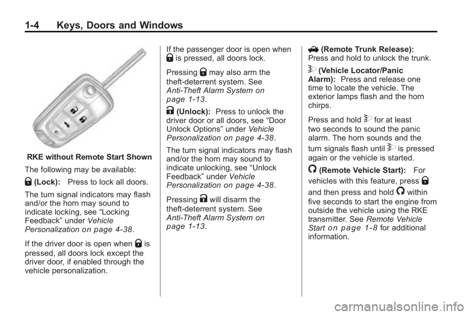
RKE without Remote Start Shown
The following may be available:
Q(Lock): Press to lock all doors.
The turn signal indicators may flash
and/or the horn may sound to
indicate locking, see “Locking
Feedback” underVehicle
Personalization
on page 4‑38.
If the driver door is open when
Qis
pressed, all doors lock except the
driver door, if enabled through the
vehicle personalization. If the passenger door is open when
Qis pressed, all doors lock.
Pressing
Qmay also arm the
theft-deterrent system. See
Anti-Theft Alarm System
on
page 1‑13.
K(Unlock): Press to unlock the
driver door or all doors, see “Door
Unlock Options” underVehicle
Personalization
on page 4‑38.
The turn signal indicators may flash
and/or the horn may sound to
indicate unlocking, see “Unlock
Feedback” underVehicle
Personalization
on page 4‑38.
Pressing
Kwill disarm the
theft-deterrent system. See
Anti-Theft Alarm System
on
page 1‑13. V
(Remote Trunk Release):
Press and hold to unlock the trunk.
7(Vehicle Locator/Panic
Alarm): Press and release one
time to locate the vehicle. The
exterior lamps flash and the horn
chirps.
Press and hold
7for at least
two seconds to sound the panic
alarm. The horn sounds and the
turn signals flash until
7is pressed
again or the vehicle is started.
/(Remote Vehicle Start): For
vehicles with this feature, press
Q
and then press and hold/within
five seconds to start the engine from
outside the vehicle using the RKE
transmitter. See Remote Vehicle
Start
on page 1‑8for additional
information.
Page 19 of 414
Keys, Doors and Windows 1-13
Vehicle Security
Vehicle theft is big business,
especially in some cities. This
vehicle has theft-deterrent features,
however, they do not make it
impossible to steal.
Anti-Theft Alarm System
This vehicle has an anti-theft alarm
system.
Arming the System
To arm the system, pressQon the
RKE transmitter.
The alarm automatically arms after
about 30 seconds. The security
light, located on the instrument
panel, flashes.
Press
Von the RKE transmitter to
open the trunk without setting off the
alarm. The system rearms when the
trunk is closed.
Disarming the System
To disarm the system, do one of the
following:
.PressKon the RKE transmitter.
.Approach the vehicle with the
RKE transmitter (Keyless
Access).
.Start the engine.
The alarm automatically disarms.
How to Detect a Tamper
Condition
IfKis pressed and the horn
sounds, an attempted break-in has
occurred while the system was
armed.
If the alarm has been activated, the
Theft Attempted message will
appear on the DIC. See Key and
Lock Messages
on page 4‑36for
additional information.
Immobilizer
See Radio Frequency Statement
(US, Can)on page 12‑16for
information regarding Part 15 of
the Federal Communications
Commission (FCC) Rules and
RSS-210/211 of Industry and
Science Canada.
Immobilizer Operation
(Key Access)
This vehicle has a passive
theft-deterrent system.
The system does not have to be
manually armed or disarmed.
The vehicle is automatically
immobilized when the key is
removed from the ignition.
The system is automatically
disarmed when the vehicle is
started with the correct key. The key
uses a transponder that matches an
immobilizer control unit in the
vehicle and automatically disarms
Page 89 of 414
Instruments and Controls 4-1
Instruments and
Controls
Instrument Panel Overview
Instrument Panel Overview . . . . 4-4
Controls
Steering Wheel Adjustment . . . 4-6
Steering Wheel Controls . . . . . . 4-6
Heated Steering Wheel . . . . . . . 4-7
Horn . . . . . . . . . . . . . . . . . . . . . . . . . . 4-7
Windshield Wiper/Washer . . . . . 4-7
Compass . . . . . . . . . . . . . . . . . . . . . 4-8
Clock (Without DateDisplay) . . . . . . . . . . . . . . . . . . . . . 4-9
Clock (With Date Display) . . . . . 4-9
Power Outlets . . . . . . . . . . . . . . . 4-10
Warning Lights, Gages, and
Indicators
Warning Lights, Gages, and Indicators . . . . . . . . . . . . . . 4-12
Instrument Cluster . . . . . . . . . . . 4-13
Speedometer . . . . . . . . . . . . . . . . 4-14
Odometer . . . . . . . . . . . . . . . . . . . . 4-14
Tachometer . . . . . . . . . . . . . . . . . . 4-14
Fuel Gage . . . . . . . . . . . . . . . . . . . 4-14
Engine Coolant Temperature Gage . . . . . . . . . 4-15
Safety Belt Reminders . . . . . . . 4-15
Airbag Readiness Light . . . . . . 4-16
Passenger Airbag Status Indicator . . . . . . . . . . . . . . . . . . . . 4-16
Charging System Light . . . . . . 4-17
Malfunction Indicator Lamp . . . . . . . . . . . . . 4-17
Brake System Warning Light . . . . . . . . . . . . . . . . . . . . . . . 4-20 Electric Parking Brake
Light . . . . . . . . . . . . . . . . . . . . . . . 4-20
Antilock Brake System (ABS) Warning Light . . . . . . . . . . . . . . 4-21
Traction Off Light . . . . . . . . . . . . 4-22
Electronic Stability Control
(ESC) Indicator Light . . . . . . . 4-22
Electronic Stability Control (ESC)/Traction Control
System (TCS) Indicator/
Warning Light . . . . . . . . . . . . . . 4-22
Tire Pressure Light . . . . . . . . . . 4-23
Engine Oil Pressure Light . . . . 4-23
Low Fuel Warning Light . . . . . . 4-24
Security Light . . . . . . . . . . . . . . . . 4-24
High-Beam on Light . . . . . . . . . 4-24
Fog Lamp Light . . . . . . . . . . . . . . 4-24
Taillamp Indicator Light . . . . . . 4-25
Cruise Control Light . . . . . . . . . 4-25
Page 93 of 414
Instruments and Controls 4-5
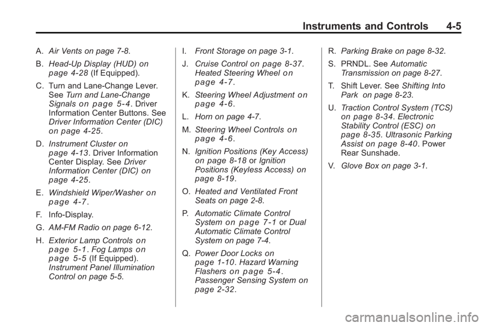
A.Air Vents on page 7‑8.
B. Head-Up Display (HUD)
on
page 4‑28(If Equipped).
C. Turn and Lane-Change Lever. See Turn and Lane-Change
Signals
on page 5‑4. Driver
Information Center Buttons. See
Driver Information Center (DIC)
on page 4‑25.
D. Instrument Cluster
on
page 4‑13. Driver Information
Center Display. See Driver
Information Center (DIC)
on
page 4‑25.
E. Windshield Wiper/Washer
on
page 4‑7.
F. Info-Display.
G. AM-FM Radio on page 6‑12.
H. Exterior Lamp Controls
on
page 5‑1. Fog Lampson
page 5‑5(If Equipped).
Instrument Panel Illumination
Control on page 5‑5. I.
Front Storage on page 3‑1.
J. Cruise Control
on page 8‑37.
Heated Steering Wheelon
page 4‑7.
K. Steering Wheel Adjustment
on
page 4‑6.
L. Horn on page 4‑7.
M. Steering Wheel Controls
on
page 4‑6.
N. Ignition Positions (Key Access)
on page 8‑18orIgnition
Positions (Keyless Access)on
page 8‑19.
O. Heated and Ventilated Front
Seats on page 2‑8.
P. Automatic Climate Control
System
on page 7‑1orDual
Automatic Climate Control
System on page 7‑4.
Q. Power Door Locks
on
page 1‑10. Hazard Warning
Flasherson page 5‑4.
Passenger Sensing Systemon
page 2‑32. R.
Parking Brake on page 8‑32.
S. PRNDL. See Automatic
Transmission on page 8‑27.
T. Shift Lever. See Shifting Into
Park on page 8‑23.
U. Traction Control System (TCS)
on page 8‑34.Electronic
Stability Control (ESC)on
page 8‑35. Ultrasonic Parking
Assiston page 8‑40. Power
Rear Sunshade.
V. Glove Box on page 3‑1.
Page 95 of 414
Instruments and Controls 4-7
Heated Steering Wheel
For vehicles with a heated steering
wheel, the button for this feature is
located on the climate control
system.
(:Press to turn the heated
steering wheel on or off. A light on
the button displays when the feature
is turned on.
The steering wheel takes about
three minutes to start heating.
Horn
Press near or on the horn symbols
on the steering wheel pad to sound
the horn.
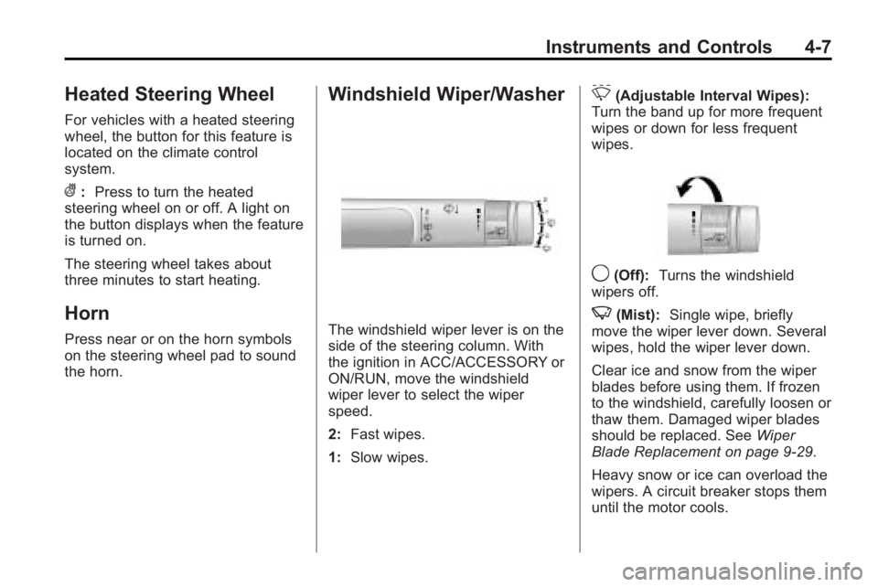
Windshield Wiper/Washer
The windshield wiper lever is on the
side of the steering column. With
the ignition in ACC/ACCESSORY or
ON/RUN, move the windshield
wiper lever to select the wiper
speed.
2: Fast wipes.
1: Slow wipes.
&(Adjustable Interval Wipes):
Turn the band up for more frequent
wipes or down for less frequent
wipes.
9(Off): Turns the windshield
wipers off.
3(Mist): Single wipe, briefly
move the wiper lever down. Several
wipes, hold the wiper lever down.
Clear ice and snow from the wiper
blades before using them. If frozen
to the windshield, carefully loosen or
thaw them. Damaged wiper blades
should be replaced. See Wiper
Blade Replacement on page 9‑29.
Heavy snow or ice can overload the
wipers. A circuit breaker stops them
until the motor cools.
Page 130 of 414
4-42 Instruments and Controls
Auto Door Unlock
This allows selection of which of the
doors will automatically unlock when
the vehicle is shifted into P (Park).
Press the MENU / SELECT knob
when Auto Door Unlock is
highlighted. Turn the knob to select
All Doors, Driver Door, or Off. Press
the knob to confirm and go back to
the last menu.
Remote Lock/Unlock/Start
Select Remote Lock/Unlock/Start
and the following will be displayed:
.Unlock Feedback (Lights)
.Locking Feedback
.Door Unlock Options
.Remote Vehicle Start
.Remote RecallUnlock Feedback (Lights)
When on, the exterior lamps will
flash when unlocking the vehicle
with the RKE transmitter.
Press the MENU / SELECT knob
when Unlock Feedback (Lights) is
highlighted. Turn the knob to select
Flash Lights or Off. Press the knob
to confirm and go back to the
last menu.
Locking Feedback
This allows selection of what type of
feedback is given when locking the
vehicle with the RKE transmitter.
Press the MENU / SELECT knob
when Locking Feedback is
highlighted. Turn the knob to select
Lights and Horn, Lights Only, Horn
Only, or Off. Press the knob to
confirm and go back to the
last menu. Door Unlock Options
This allows selection of which doors
will unlock when pressing the unlock
button on the RKE transmitter.
Press the MENU / SELECT knob
when Door Unlock Options is
highlighted. Turn the knob to select
All Doors or Driver Door Only. When
set to Driver Door Only, the driver
door will unlock the first time the
unlock button is pressed and all
doors will unlock when the button is
pressed a second time. When set to
All Doors, all of the doors will unlock
at the first press of the unlock
button. Press the knob to confirm
and go back to the last menu.
Remote Vehicle Start
This allows the Remote Vehicle
Start to be turned on or off, if the
vehicle has this feature.
Press the MENU / SELECT knob
when Remote Vehicle Start is
highlighted. Turn the knob to select
On or Off. Press the knob to confirm
and go back to the last menu.
Page 322 of 414
9-40 Vehicle Care
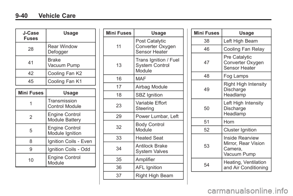
J-CaseFuses Usage
28 Rear Window
Defogger
41 Brake
Vacuum Pump
42 Cooling Fan K2
45 Cooling Fan K1
Mini Fuses Usage 1 Transmission
Control Module
2 Engine Control
Module Battery
5 Engine Control
Module Ignition
8 Ignition Coils ‐Even
9 Ignition Coils ‐Odd
10 Engine Control
Module Mini Fuses Usage
11 Post Catalytic
Converter Oxygen
Sensor Heater
13 Trans Ignition / Fuel
System Control
Module
16 MAF
17 Airbag Module
18 SBZ Ignition
23 Variable Effort
Steering
29 Power Lumbar, Left
32 Body Control
Module
33 Heated Seat
34 Antilock Brake
System Valves
35 Amplifier
36 AFL Ignition
37 Right High Beam Mini Fuses Usage
38 Left High Beam
46 Cooling Fan Relay
47 Pre Catalytic
Converter Oxygen
Sensor Heater
48 Fog Lamps
49 Right High Intensity
Discharge
Headlamp
50 Left High Intensity
Discharge
Headlamp
51 Horn
52 Cluster Ignition
53 Inside Rearview
Mirror, Rear Vision
Camera,
Vacuum Pump
54 Heating, Ventilation
and Air Conditioning
Page 323 of 414
Vehicle Care 9-41
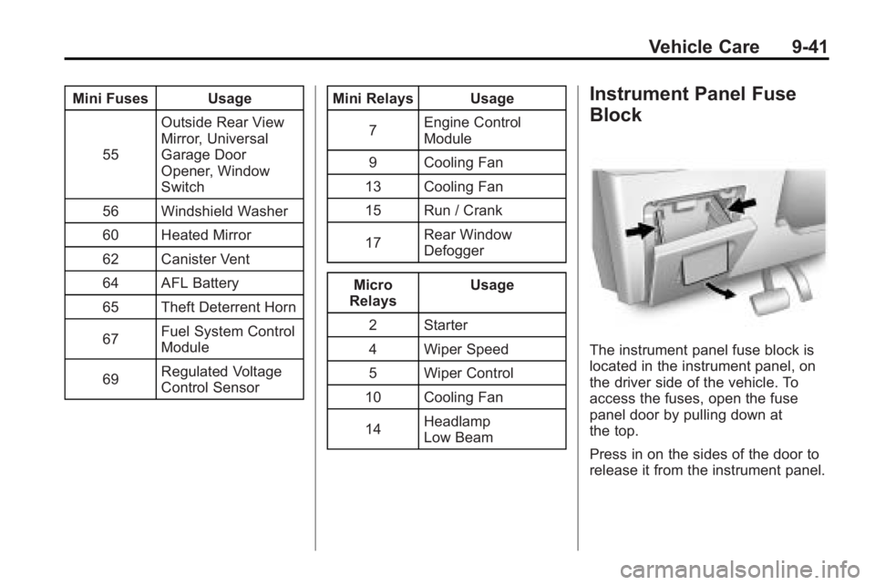
Mini Fuses Usage55 Outside Rear View
Mirror, Universal
Garage Door
Opener, Window
Switch
56 Windshield Washer
60 Heated Mirror
62 Canister Vent
64 AFL Battery
65 Theft Deterrent Horn
67 Fuel System Control
Module
69 Regulated Voltage
Control Sensor Mini Relays Usage
7 Engine Control
Module
9 Cooling Fan
13 Cooling Fan
15 Run / Crank
17 Rear Window
Defogger
Micro
Relays Usage
2 Starter
4 Wiper Speed
5 Wiper Control
10 Cooling Fan
14 Headlamp
Low BeamInstrument Panel Fuse
Block
The instrument panel fuse block is
located in the instrument panel, on
the driver side of the vehicle. To
access the fuses, open the fuse
panel door by pulling down at
the top.
Press in on the sides of the door to
release it from the instrument panel.
Page 340 of 414
9-58 Vehicle Care
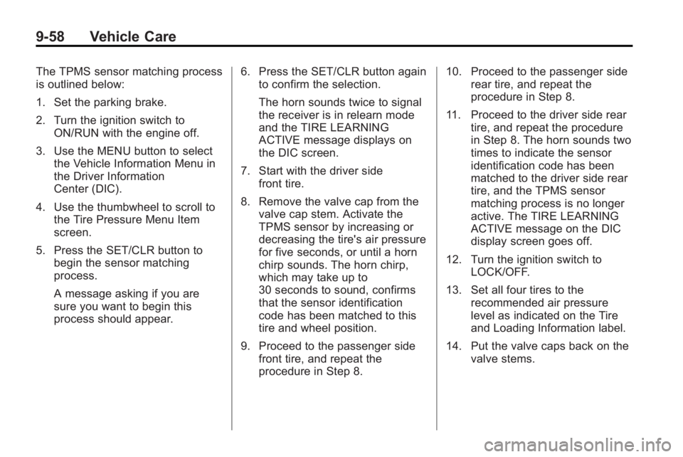
The TPMS sensor matching process
is outlined below:
1. Set the parking brake.
2. Turn the ignition switch toON/RUN with the engine off.
3. Use the MENU button to select the Vehicle Information Menu in
the Driver Information
Center (DIC).
4. Use the thumbwheel to scroll to the Tire Pressure Menu Item
screen.
5. Press the SET/CLR button to begin the sensor matching
process.
A message asking if you are
sure you want to begin this
process should appear. 6. Press the SET/CLR button again
to confirm the selection.
The horn sounds twice to signal
the receiver is in relearn mode
and the TIRE LEARNING
ACTIVE message displays on
the DIC screen.
7. Start with the driver side front tire.
8. Remove the valve cap from the valve cap stem. Activate the
TPMS sensor by increasing or
decreasing the tire's air pressure
for five seconds, or until a horn
chirp sounds. The horn chirp,
which may take up to
30 seconds to sound, confirms
that the sensor identification
code has been matched to this
tire and wheel position.
9. Proceed to the passenger side front tire, and repeat the
procedure in Step 8. 10. Proceed to the passenger side
rear tire, and repeat the
procedure in Step 8.
11. Proceed to the driver side rear tire, and repeat the procedure
in Step 8. The horn sounds two
times to indicate the sensor
identification code has been
matched to the driver side rear
tire, and the TPMS sensor
matching process is no longer
active. The TIRE LEARNING
ACTIVE message on the DIC
display screen goes off.
12. Turn the ignition switch to LOCK/OFF.
13. Set all four tires to the recommended air pressure
level as indicated on the Tire
and Loading Information label.
14. Put the valve caps back on the valve stems.
Page 408 of 414
i-6 INDEX
Heated and Ventilated FrontSeats . . . . . . . . . . . . . . . . . . . . . . . . . 2-8
Heated Front Seats . . . . . . . . . . . . . 2-8
Heated Mirrors . . . . . . . . . . . . . . . . . 1-16
High-Beam On Light . . . . . . . . . . . 4-24
Highway Hypnosis . . . . . . . . . . . . . . 8-8
Hill and Mountain Roads . . . . . . . . 8-9
Hood . . . . . . . . . . . . . . . . . . . . . . . . . . . 9-5
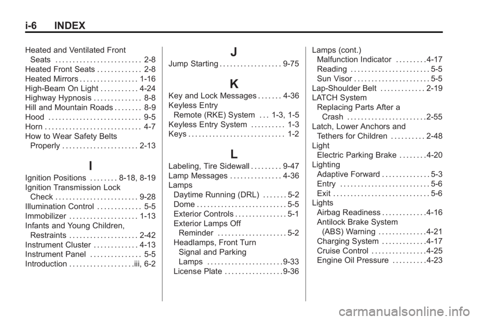
Horn . . . . . . . . . . . . . . . . . . . . . . . . . . . . 4-7
How to Wear Safety Belts Properly . . . . . . . . . . . . . . . . . . . . . . 2-13
I
Ignition Positions . . . . . . . . 8-18, 8-19
Ignition Transmission Lock
Check . . . . . . . . . . . . . . . . . . . . . . . . 9-28
Illumination Control . . . . . . . . . . . . . 5-5
Immobilizer . . . . . . . . . . . . . . . . . . . . 1-13
Infants and Young Children, Restraints . . . . . . . . . . . . . . . . . . . . 2-42
Instrument Cluster . . . . . . . . . . . . . 4-13
Instrument Panel . . . . . . . . . . . . . . . 5-5
Introduction . . . . . . . . . . . . . . . . . . .iii, 6-2
J
Jump Starting . . . . . . . . . . . . . . . . . . 9-75
K
Key and Lock Messages . . . . . . . 4-36
Keyless Entry Remote (RKE) System . . . 1-3, 1-5
Keyless Entry System . . . . . . . . . . 1-3
Keys . . . . . . . . . . . . . . . . . . . . . . . . . . . . 1-2
L
Labeling, Tire Sidewall . . . . . . . . . 9-47
Lamp Messages . . . . . . . . . . . . . . . 4-36
Lamps Daytime Running (DRL) . . . . . . . 5-2
Dome . . . . . . . . . . . . . . . . . . . . . . . . . . 5-5
Exterior Controls . . . . . . . . . . . . . . . 5-1
Exterior Lamps Off
Reminder . . . . . . . . . . . . . . . . . . . . 5-2
Headlamps, Front Turn
Signal and Parking
Lamps . . . . . . . . . . . . . . . . . . . . . . 9-33
License Plate . . . . . . . . . . . . . . . . . 9-36 Lamps (cont.)
Malfunction Indicator . . . . . . . . . 4-17
Reading . . . . . . . . . . . . . . . . . . . . . . . 5-5
Sun Visor . . . . . . . . . . . . . . . . . . . . . . 5-5
Lap-Shoulder Belt . . . . . . . . . . . . . 2-19
LATCH System Replacing Parts After aCrash . . . . . . . . . . . . . . . . . . . . . . . 2-55
Latch, Lower Anchors and
Tethers for Children . . . . . . . . . . 2-48
Light Electric Parking Brake . . . . . . . . 4-20
Lighting Adaptive Forward . . . . . . . . . . . . . . 5-3
Entry . . . . . . . . . . . . . . . . . . . . . . . . . . 5-6
Exit . . . . . . . . . . . . . . . . . . . . . . . . . . . . 5-6
Lights Airbag Readiness . . . . . . . . . . . . . 4-16
Antilock Brake System
(ABS) Warning . . . . . . . . . . . . . . 4-21
Charging System . . . . . . . . . . . . . 4-17
Cruise Control . . . . . . . . . . . . . . . . 4-25
Engine Oil Pressure . . . . . . . . . . 4-23