DIC BUICK LESABRE 2005 Manual PDF
[x] Cancel search | Manufacturer: BUICK, Model Year: 2005, Model line: LESABRE, Model: BUICK LESABRE 2005Pages: 392, PDF Size: 2.45 MB
Page 285 of 392
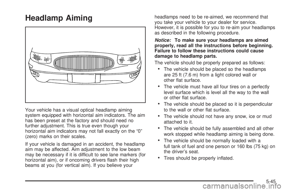
Headlamp Aiming
Your vehicle has a visual optical headlamp aiming
system equipped with horizontal aim indicators. The aim
has been preset at the factory and should need no
further adjustment. This is true even though your
horizontal aim indicators may not fall exactly on the “0”
(zero) marks on their scales.
If your vehicle is damaged in an accident, the headlamp
aim may be affected. Aim adjustment to the low beam
may be necessary if it is difficult to see lane markers (for
horizontal aim), or if oncoming drivers �ash their high
beams at you (for vertical aim). If you believe yourheadlamps need to be re-aimed, we recommend that
you take your vehicle to your dealer for service.
However, it is possible for you to re-aim your headlamps
as described in the following procedure.
Notice:To make sure your headlamps are aimed
properly, read all the instructions before beginning.
Failure to follow these instructions could cause
damage to headlamp parts.
The vehicle should be properly prepared as follows:
The vehicle should be placed so the headlamps
are 25 ft (7.6 m) from a light colored wall or
other �at surface.
The vehicle must have all four tires on a perfectly
level surface which is level all the way to the wall
or other �at surface.
The vehicle should be placed so it is perpendicular
to the wall or other �at surface.
The vehicle should not have any snow, ice or mud
attached to it.
The vehicle should be fully assembled and all other
work stopped while headlamp aiming is being done.
The vehicle should be normally loaded with a
full tank of fuel and one person or 160 lbs (75 kg) on
the driver’s seat.
Tires should be properly in�ated.
5-45
Page 286 of 392

Headlamp aiming is done with the vehicle low-beam
lamps. The high-beam lamps will be correctly aimed if
the low-beam lamps are aimed properly.
The headlamp aiming devices are located under the
hood near the headlamps.
If you believe your headlamps need horizontal (left/right)
adjustment, follow the horizontal aiming procedure. If
you believe your headlamps need only vertical
(up/down) adjustment, follow only the vertical
aiming procedure.
Adjustment screws can be turned with an E8 Torx
®
socket or T15 Torx®screwdriver.
Headlamp Horizontal Aiming
To adjust the horizontal aim, do the following:
1. Open the hood. SeeHood Release on page 5-11
for more information.
2. Locate the horizontal aiming screw (A).
3. Turn the horizontal aiming screw (A) until the
indicator (B) is lined up with zero.
Once the horizontal aim is adjusted, then adjust the
vertical aim.
5-46
Page 295 of 392
Tire Sidewall Labelling
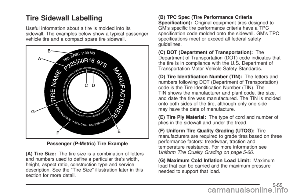
Useful information about a tire is molded into its
sidewall. The examples below show a typical passenger
vehicle tire and a compact spare tire sidewall.
(A) Tire Size:The tire size is a combination of letters
and numbers used to de�ne a particular tire’s width,
height, aspect ratio, construction type and service
description. See the “Tire Size” illustration later in this
section for more detail.(B) TPC Spec (Tire Performance Criteria
Speci�cation):Original equipment tires designed to
GM’s speci�c tire performance criteria have a TPC
speci�cation code molded onto the sidewall. GM’s TPC
speci�cations meet or exceed all federal safety
guidelines.
(C) DOT (Department of Transportation):The
Department of Transportation (DOT) code indicates that
the tire is in compliance with the U.S. Department of
Transportation Motor Vehicle Safety Standards.
(D) Tire Identi�cation Number (TIN):The letters and
numbers following DOT (Department of Transportation)
code is the Tire Identi�cation Number (TIN). The
TIN shows the manufacturer and plant code, tire size,
and date the tire was manufactured. The TIN is molded
onto both sides of the tire, although only one side
may have the date of manufacture.
(E) Tire Ply Material:The type of cord and number of
plies in the sidewall and under the tread.
(F) Uniform Tire Quality Grading (UTQG):Tire
manufacturers are required to grade tires based on three
performance factors: treadwear, traction and
temperature resistance. For more information see
Uniform Tire Quality Grading on page 5-66.
(G) Maximum Cold In�ation Load Limit:Maximum
load that can be carried and the maximum pressure
needed to support that load. Passenger (P-Metric) Tire Example
5-55
Page 297 of 392
Tire Size
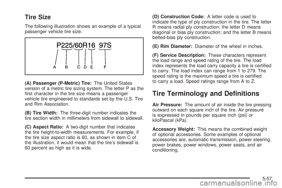
The following illustration shows an example of a typical
passenger vehicle tire size.
(A) Passenger (P-Metric) Tire:The United States
version of a metric tire sizing system. The letter P as the
�rst character in the tire size means a passenger
vehicle tire engineered to standards set by the U.S. Tire
and Rim Association.
(B) Tire Width:The three-digit number indicates the
tire section width in millimeters from sidewall to sidewall.
(C) Aspect Ratio:A two-digit number that indicates
the tire height-to-width measurements. For example, if
the tire size aspect ratio is 60, as shown in item C of
the illustration, it would mean that the tire’s sidewall is
60 percent as high as it is wide.(D) Construction Code:A letter code is used to
indicate the type of ply construction in the tire. The letter
R means radial ply construction; the letter D means
diagonal or bias ply construction; and the letter B means
belted-bias ply construction.
(E) Rim Diameter:Diameter of the wheel in inches.
(F) Service Description:These characters represent
the load range and speed rating of the tire. The load
index represents the load carry capacity a tire is certi�ed
to carry. The load index can range from 1 to 279. The
speed rating is the maximum speed a tire is certi�ed
to carry a load. Speed ratings range from A to Z.
Tire Terminology and De�nitions
Air Pressure:The amount of air inside the tire pressing
outward on each square inch of the tire. Air pressure
is expressed in pounds per square inch (psi) or
kiloPascal (kPa).
Accessory Weight:This means the combined weight
of optional accessories. Some examples of optional
accessories are, automatic transmission, power steering,
power brakes, power windows, power seats, and air
conditioning.
5-57
Page 299 of 392
Normal Occupant Weight:The number of occupants a
vehicle is designed to seat multiplied by 150 lbs (68 kg).
SeeLoading Your Vehicle on page 4-31.
Occupant Distribution:Designated seating positions.
Outward Facing Sidewall:The side of an
asymmetrical tire that has a particular side that faces
outward when mounted on a vehicle. The side of the tire
that contains a whitewall, bears white lettering or
bears manufacturer, brand, and/or model name molding
that is higher or deeper than the same moldings on
the other sidewall of the tire.
Passenger (P-Metric) Tire:A tire used on
passenger cars and some light duty trucks and
multipurpose vehicles.
Recommended In�ation Pressure:Vehicle
manufacturer’s recommended tire in�ation pressure and
shown on the tire placard. SeeIn�ation - Tire Pressure
on page 5-60andLoading Your Vehicle on page 4-31.
Radial Ply Tire:A pneumatic tire in which the ply cords
that extend to the beads are laid at 90 degrees to the
centerline of the tread.Rim:A metal support for a tire and upon which the tire
beads are seated.
Sidewall:The portion of a tire between the tread and
the bead.
Speed Rating:An alphanumeric code assigned to a
tire indicating the maximum speed at which a tire
can operate.
Traction:The friction between the tire and the road
surface. The amount of grip provided.
Tread:The portion of a tire that comes into contact
with the road.
Treadwear Indicators:Narrow bands, sometimes
called “wear bars,” that show across the tread of a tire
when only 1/16 inch (1.6 mm) of tread remains. See
When It Is Time for New Tires on page 5-64.
UTQGS (Uniform Tire Quality Grading Standards):A
tire information system that provides consumers with
ratings for a tire’s traction, temperature, and treadwear.
Ratings are determined by tire manufacturers using
government testing procedures. The ratings are molded
into the sidewall of the tire. SeeUniform Tire Quality
Grading on page 5-66.
5-59
Page 302 of 392
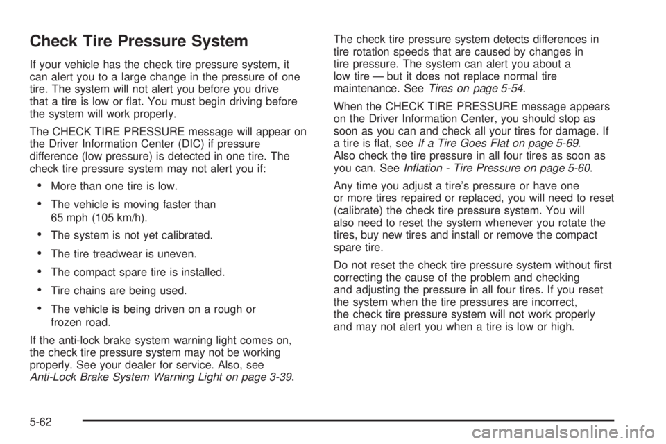
Check Tire Pressure System
If your vehicle has the check tire pressure system, it
can alert you to a large change in the pressure of one
tire. The system will not alert you before you drive
that a tire is low or �at. You must begin driving before
the system will work properly.
The CHECK TIRE PRESSURE message will appear on
the Driver Information Center (DIC) if pressure
difference (low pressure) is detected in one tire. The
check tire pressure system may not alert you if:
More than one tire is low.
The vehicle is moving faster than
65 mph (105 km/h).
The system is not yet calibrated.
The tire treadwear is uneven.
The compact spare tire is installed.
Tire chains are being used.
The vehicle is being driven on a rough or
frozen road.
If the anti-lock brake system warning light comes on,
the check tire pressure system may not be working
properly. See your dealer for service. Also, see
Anti-Lock Brake System Warning Light on page 3-39.The check tire pressure system detects differences in
tire rotation speeds that are caused by changes in
tire pressure. The system can alert you about a
low tire — but it does not replace normal tire
maintenance. SeeTires on page 5-54.
When the CHECK TIRE PRESSURE message appears
on the Driver Information Center, you should stop as
soon as you can and check all your tires for damage. If
a tire is �at, seeIf a Tire Goes Flat on page 5-69.
Also check the tire pressure in all four tires as soon as
you can. SeeIn�ation - Tire Pressure on page 5-60.
Any time you adjust a tire’s pressure or have one
or more tires repaired or replaced, you will need to reset
(calibrate) the check tire pressure system. You will
also need to reset the system whenever you rotate the
tires, buy new tires and install or remove the compact
spare tire.
Do not reset the check tire pressure system without �rst
correcting the cause of the problem and checking
and adjusting the pressure in all four tires. If you reset
the system when the tire pressures are incorrect,
the check tire pressure system will not work properly
and may not alert you when a tire is low or high.
5-62
Page 303 of 392
To reset (calibrate) the system:
1. Turn the ignition switch to RUN.
2. Press the GAGE INFO button on the DIC until TIRE
PRESSURE appears on the display.
3. Press and hold the DIC RESET button for about
�ve seconds. After �ve seconds, the display will
show TIRE PRESSURE RESET. If TIRE
PRESSURE RESET does not appear in the display
after about �ve seconds repeat the procedure. If it
does not work after two tries, see your dealer for
service. After you release the DIC RESET button,
TIRE PRESSURE NORMAL will appear in the
display.
The system completes the calibration process during
driving. Calibration time can take 45 to 90 minutes,
depending on your driving habits. After the system has
been calibrated, the system will alert the driver that
a tire is low, up to a maximum speed of 65 mph
(105 km/h).
Tire Inspection and Rotation
Tires should be rotated every 5,000 to 8,000 miles
(8 000 to 13 000 km).Any time you notice unusual wear rotate your tires as
soon as possible and check wheel alignment. Also
check for damaged tires or wheels. SeeWhen It Is Time
for New Tires on page 5-64andWheel Replacement
on page 5-67for more information.
The purpose of regular rotation is to achieve more
uniform wear for all tires on the vehicle. The �rst rotation
is the most important. SeePart A: Scheduled
Maintenance Services on page 6-4, for scheduled
rotation intervals.
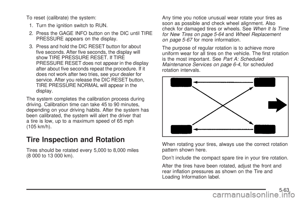
When rotating your tires, always use the correct rotation
pattern shown here.
Don’t include the compact spare tire in your tire rotation.
After the tires have been rotated, adjust the front and
rear in�ation pressures as shown on the Tire and
Loading Information label.
5-63
Page 304 of 392
Reset the check tire pressure system, if equipped. See
Check Tire Pressure System on page 5-62.
Make certain that all wheel nuts are properly tightened.
See “Wheel Nut Torque” underCapacities and
Speci�cations on page 5-96.
{CAUTION:
Rust or dirt on a wheel, or on the parts to
which it is fastened, can make wheel nuts
become loose after a time. The wheel could
come off and cause an accident. When you
change a wheel, remove any rust or dirt from
places where the wheel attaches to the vehicle.
In an emergency, you can use a cloth or a
paper towel to do this; but be sure to use a
scraper or wire brush later, if you need to, to
get all the rust or dirt off. SeeChanging a Flat
Tire on page 5-70.
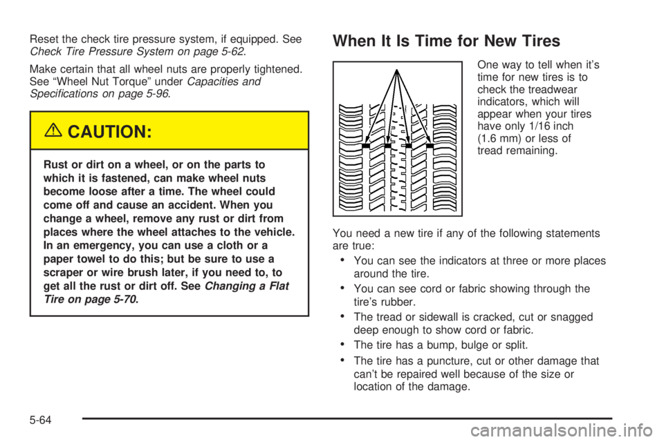
When It Is Time for New Tires
One way to tell when it’s
time for new tires is to
check the treadwear
indicators, which will
appear when your tires
have only 1/16 inch
(1.6 mm) or less of
tread remaining.
You need a new tire if any of the following statements
are true:
You can see the indicators at three or more places
around the tire.
You can see cord or fabric showing through the
tire’s rubber.
The tread or sidewall is cracked, cut or snagged
deep enough to show cord or fabric.
The tire has a bump, bulge or split.
The tire has a puncture, cut or other damage that
can’t be repaired well because of the size or
location of the damage.
5-64
Page 339 of 392
Maintenance Schedule......................................6-2
Introduction...................................................6-2
Maintenance Requirements..............................6-2
Your Vehicle and the Environment....................6-2
How This Section is Organized.........................6-3
Part A: Scheduled Maintenance Services...........6-4
Using Your Maintenance Schedule....................6-4
Selecting the Right Schedule...........................6-5
Short Trip/City Scheduled Maintenance..............6-6
Long Trip/Highway Scheduled Maintenance......6-13
Part B: Owner Checks and Services................6-18
At Each Fuel Fill..........................................6-18
At Least Once a Month.................................6-18At Least Twice a Year...................................6-19
At Least Once a Year...................................6-19
Part C: Periodic Maintenance Inspections.........6-22
Steering, Suspension and Front Drive Axle
Boot and Seal Inspection............................6-22
Exhaust System Inspection............................6-22
Fuel System Inspection..................................6-23
Engine Cooling System Inspection...................6-23
Throttle System Inspection.............................6-23
Brake System Inspection................................6-23
Part D: Recommended Fluids and Lubricants. . . .6-24
Part E: Maintenance Record...........................6-25
Section 6 Maintenance Schedule
6-1
Page 341 of 392
How This Section is Organized
This maintenance schedule is divided into �ve parts:
“Part A: Scheduled Maintenance Services”explains
what to have done and how often. Some of these
services can be complex, so unless you are technically
quali�ed and have the necessary equipment, you
should let your GM dealer’s service department do
these jobs.
Your GM dealer has GM-trained and supported
service people that will perform the work using genuine
GM parts.
{CAUTION:
Performing maintenance work on a vehicle can
be dangerous. In trying to do some jobs, you
can be seriously injured. Do your own
maintenance work only if you have the
required know-how and the proper tools and
equipment for the job. If you have any doubt,
have a quali�ed technician do the work.
If you want to purchase service information, seeService
Publications Ordering Information on page 7-11.“Part B: Owner Checks and Services”tells you
what should be checked and when. It also explains
what you can easily do to help keep your vehicle in
good condition.
“Part C: Periodic Maintenance Inspections”explains
important inspections that your dealer’s service
department can perform for you.
“Part D: Recommended Fluids and Lubricants”lists
some recommended products necessary to help
keep your vehicle properly maintained. These products,
or their equivalents, should be used whether you do
the work yourself or have it done.
“Part E: Maintenance Record”is a place for you to
record and keep track of the maintenance performed
on your vehicle. Keep your maintenance receipts.
They may be needed to qualify your vehicle for
warranty repairs.
6-3