CADILLAC CTS V 2006 1.G Owners Manual
Manufacturer: CADILLAC, Model Year: 2006, Model line: CTS V, Model: CADILLAC CTS V 2006 1.GPages: 442, PDF Size: 2.57 MB
Page 341 of 442

High Speed Operation (CTS-V)
{CAUTION:
Driving at high speeds, 100 mph (160 km/h)
or higher, puts an additional strain on tires.
Sustained high-speed driving causes
excessive heat build up and can cause sudden
tire failure. You could have a crash and you or
others could be killed. Some high-speed rated
tires require in�ation pressure adjustment for
high speed operation. When speed limits and
road conditions are such that a vehicle can be
driven at high speeds, make sure the tires are
rated for high speed operation, in excellent
condition, and set to the correct cold tire
in�ation pressure for the vehicle load.
The CTS-V high-performance tires, size 245/45R18 96V
and P245/45ZR18 96W require in�ation pressure
adjustment when driving your vehicle at speeds of
100 mph (160 km/h) or higher. Set the cold tire in�ation
pressure to the maximum in�ation pressure shown
on the tire sidewall, or 41 psi (282 kPa), whichever
is lower.See the example following.
Example:
You will �nd the maximum load and in�ation pressure
molded on the tire’s sidewall, in small letters, near
the rim �ange. It will read something like this: Maximum
load 710 kg (1565 lbs) 350 kPa (51 psi) Max. Press.
For this example, you would set the cold in�ation
pressure for high-speed driving at 41 psi (282 kPa)
When you end high-speed driving, return the tires to
the cold in�ation pressures shown on the tire and
loading information label. SeeLoading Your Vehicle
on page 4-32.
5-67
Page 342 of 442

Tire Pressure Monitor System
The Tire Pressure Monitor System (TPMS) uses radio
and sensor technology to check tire pressure levels.
If your vehicle has this feature, sensors are mounted on
the tire and wheel assembly. The TPMS sensors
transmit tire pressure readings to a receiver located in
the vehicle once every 60 seconds while the vehicle
is being driven, and once every 60 minutes if the vehicle
is stationary for more than 15 minutes.
If your vehicle has the base audio system, the Driver
Information Center (DIC) displays TPMS warnings and
messages on the radio’s display screen. SeeSystem
Controls on page 3-53andDIC Warnings and Messages
on page 3-61for additional information and details about
the DIC operation and displays. If your vehicle has the
Navigation system, TPMS warnings and messages are
displayed on the message center screen, located inside
the tachometer. SeeMessage Center (CTS-V) on
page 3-47for information about the message center
operation and displays.
If a low tire pressure condition is detected, the TPMS
will display the Check Tire Pressure message on
the DIC or message center and, at the same time,
illuminate the low tire pressure warning symbol on
the instrument panel cluster.Each tire, including the spare (if provided), should be
checked monthly when cold and in�ated to the in�ation
pressure recommended by the vehicle manufacturer
on the vehicle placard or tire in�ation pressure label.
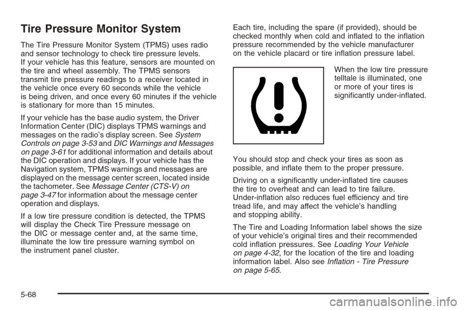
When the low tire pressure
telltale is illuminated, one
or more of your tires is
signi�cantly under-in�ated.
You should stop and check your tires as soon as
possible, and in�ate them to the proper pressure.
Driving on a signi�cantly under-in�ated tire causes
the tire to overheat and can lead to tire failure.
Under-in�ation also reduces fuel efficiency and tire
tread life, and may affect the vehicle’s handling
and stopping ability.
The Tire and Loading Information label shows the size
of your vehicle’s original tires and their recommended
cold in�ation pressures. SeeLoading Your Vehicle
on page 4-32, for the location of the tire and loading
information label. Also seeIn�ation - Tire Pressure
on page 5-65.
5-68
Page 343 of 442

Your vehicle’s TPMS can alert you about a low tire
pressure condition but it does not replace normal tire
maintenance. SeeTire Inspection and Rotation on
page 5-71andTires on page 5-57.
Notice:Do not use a tire sealant if your vehicle
has Tire Pressure Monitors. The liquid sealant can
damage the tire pressure monitor sensors.
TPMS Sensor Identi�cation Codes
Each TPMS sensor has a unique identi�cation code.
Any time you replace one or more of the TPMS sensors
or rotate the tires, the identi�cation codes will need to
be matched to the new tire and wheel position. The
sensors are matched, to the tire and wheel positions,
in the following order: left front (LF), right front (RF), right
rear (RR), and left rear (LR) using a TPMS diagnostic
tool. See your GM dealer for service.
The TPMS sensors may also be matched to each tire
and wheel position by increasing or decreasing the
tire’s air pressure. When increasing tire pressure do
not exceed the maximum in�ation pressure indicated
on the tire’s sidewall.
You will have two minutes to match the �rst tire and
wheel position, and �ve minutes overall, to match all
four tire and wheel positions. If it takes longer than
two minutes, to match the �rst tire and wheel, or more
than �ve minutes to match all four tire and wheel
positions the matching process stops and you will
need to start over.The TPM matching process is outlined below:
1. Set the parking brake.
2. Turn the ignition switch to ON with the engine off.
3. Using the Remote Keyless Entry (RKE) transmitter,
lock and unlock the vehicle’s doors.
4. Press the lock and unlock buttons, at the same
time, on the RKE transmitter. A single horn chirp
will sound, indicating that the TPMS system is
ready, and the sensor matching process can begin.
5. Start with the driver’s side front tire.
6. Remove the valve cap from the valve stem.
Activate the TPMS sensor by increasing or
decreasing the tire’s air pressure for �ve seconds,
or until a horn chirp sounds. The horn chirp,
which may take up to 30 seconds, con�rms that the
sensor identi�cation code has been matched to
this tire position. To decrease the tire’s air-pressure
use the pointed end of the valve cap, a pencil-style
air pressure gage, or a key.
7. Proceed to the passenger’s side front tire, and
repeat the procedure in Step 6.
8. Proceed to the passenger’s side rear tire, and
repeat the procedure in Step 6.
9. Proceed to the driver’s side rear tire, and repeat
the procedure in Step 6.
5-69
Page 344 of 442

10. After hearing the con�rming double horn chirp,
for the left rear tire, exit the matching process
by turning the ignition switch to OFF.
11. Set all four tires to the recommended air pressure
level as indicated on the tire and loading
information label.
12. Put the valve caps back on the valve stems.
The TPMS will not function properly, if one or more
of the TPMS sensors are missing or inoperable. If your
vehicle has a compact spare tire, the spare tire and
wheel assembly does not contain a TPMS sensor.
If you replace one of the road tires with the spare, or
if the system detects a missing or inoperable sensor, the
Service Tire Monitor System message will be displayed
on the DIC. If you have replaced a tire and wheel
assembly without transferring the TPMS sensors, the
error message will be displayed. Once you re-install the
TPMS sensors, the message should go off. See your
GM dealer for service if all TPMS sensors are installed
and the error message comes on and stays on. Have
your vehicle serviced as soon as possible.
If your vehicle has a message center and the system
detects a missing or inoperable sensor an error
message of several dashes–––willbeshown on
the message center display. If you have replaced
a tire and wheel assembly without transferring the
TPMS sensors, the error message will be displayed.Once you re-install the TPMS sensors, the error
message should go off. See your GM dealer for service
if all TPMS sensors are installed and the error
message comes on and stays on.
The TPMS operates on a radio frequency subject to
Federal Communications Commission (FCC) Rules and
with Industry and Science Canada.
This device complies with Part 15 of the FCC Rules.
Operation is subject to the following two conditions:
1. This device may not cause interference.
2. This device must accept any interference received,
including interference that may cause undesired
operation.
This device complies with RSS-210 of Industry Canada.
Operation is subject to the following two conditions:
1. This device may not cause interference.
2. This device must accept any interference received,
including interference that may cause undesired
operation of the device.
Changes or modi�cations to this system by other than
an authorized service facility could void authorization to
use this equipment.
5-70
Page 345 of 442

Tire Inspection and Rotation
Tires should be rotated every 5,000 to 8,000 miles
(8 000 to 13 000 km).
If your vehicle has P245/45ZR18 96W size tires,
GM recommends rotating these tires at 3,000 mile
(4 800 km) intervals. These tires are optimized for dry
traction and handling performance. Tread life may
be 15,000 miles (24 140 km) or less for these tires,
depending on how and where you drive.
Any time you notice unusual wear, rotate your vehicle’s
tires as soon as possible and check wheel alignment.
Also check for damaged tires or wheels. SeeWhen
It Is Time for New Tires on page 5-72andWheel
Replacement on page 5-77for more information.
The purpose of regular rotation is to achieve more
uniform wear for all tires on the vehicle. The �rst rotation
is the most important. SeeScheduled Maintenance
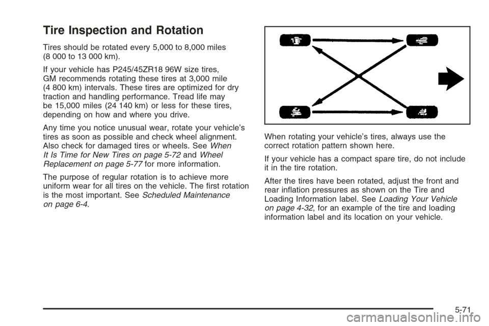
on page 6-4.When rotating your vehicle’s tires, always use the
correct rotation pattern shown here.
If your vehicle has a compact spare tire, do not include
it in the tire rotation.
After the tires have been rotated, adjust the front and
rear in�ation pressures as shown on the Tire and
Loading Information label. SeeLoading Your Vehicle
on page 4-32, for an example of the tire and loading
information label and its location on your vehicle.
5-71
Page 346 of 442

If your vehicle has the Tire Pressure Monitor System
(TPMS) the TPMS sensors will need to be reset
and matched to the tire/wheel position. A special TPMS
diagnostic tool is used to reset the sensor identi�cation
codes. See your dealer for service.
Make certain that all wheel nuts are properly tightened.
See “Wheel Nut Torque” underCapacities and
Speci�cations on page 5-115.
{CAUTION:
Rust or dirt on a wheel, or on the parts to
which it is fastened, can make wheel nuts
become loose after time. The wheel could
come off and cause an accident. When you
change a wheel, remove any rust or dirt from
places where the wheel attaches to the vehicle.
In an emergency, you can use a cloth or a
paper towel to do this; but be sure to use a
scraper or wire brush later, if needed, to get all
the rust or dirt off. SeeChanging a Flat Tire
(CTS Only) on page 5-84.
When It Is Time for New Tires
One way to tell when it is
time for new tires is to
check the treadwear
indicators, which will
appear when your tires
have only 1/16 inch
(1.6 mm) or less of tread
remaining.
You need a new tire if any of the following statements
are true:
You can see the indicators at three or more places
around the tire.
You can see cord or fabric showing through the
tire’s rubber.
The tread or sidewall is cracked, cut, or snagged
deep enough to show cord or fabric.
The tire has a bump, bulge, or split.
The tire has a puncture, cut, or other damage that
cannot be repaired well because of the size or
location of the damage.
5-72
Page 347 of 442

Buying New Tires
GM has developed and matched speci�c tires for
your vehicle. The original equipment tires installed
on your vehicle, when it was new, were designed to
meet General Motors Tire Performance Criteria
Speci�cation (TPC Spec) system rating. If you need
replacement tires, GM strongly recommends that you
get tires with the same TPC Spec rating. This way,
your vehicle will continue to have tires that are designed
to give the same performance and vehicle safety,
during normal use, as the original tires.
GM’s exclusive TPC Spec system considers over a
dozen critical speci�cations that impact the overall
performance of your vehicle, including brake system
performance, ride and handling, traction control, and
tire pressure monitoring performance. GM’s TPC Spec
number is molded onto the tire’s sidewall by the tire
manufacturer. If the tires have an all-season tread
design, the TPC Spec number will be followed by a
MS for mud and snow. SeeTire Sidewall Labeling
on page 5-58for additional information.The 18-inch performance tires, size 245/45R18 96V,
used on some vehicles, meet the General Motors Tire
Performance Criteria Speci�cation (TPC Spec) rating
but the TPC Spec code has not been molded onto
the tire’s sidewall. If your vehicle has these tires, and
you need to replace them, you can still get these
TPC Spec rated tires by asking your GM dealer.
Your GM dealer can order these tires by part number.
This way, your vehicle will continue to give the
proper endurance, handling, traction, and ride as the
original tires.
5-73
Page 348 of 442

Winter tires with the same speed rating as your vehicle’s
original equipment tires may not be available for H, V, W,
and ZR speed rated tires. If you choose snow tires with
a lower speed rating, never exceed the tire’s maximum
speed capability.
{CAUTION:
Mixing tires could cause you to lose control of
your vehicle while driving. If you mix tires of
different sizes, brands, or types (radial and
bias-belted tires) the vehicle may not handle
properly, and you could have a crash. Using
tires of different sizes, brands, or types may
also cause damage to your vehicle. Be sure to
use the correct size, brand, and type of tires
on all wheels.
Your vehicle may have a compact spare tire
and wheel assembly. It is all right to drive with
your vehicle’s compact spare tire temporarily.
It was developed for use on your vehicle. See
Compact Spare Tire (CTS Only) on page 5-94.
{CAUTION:
If you use bias-ply tires on your vehicle, the
wheel rim �anges could develop cracks after
many miles of driving. A tire and/or wheel
could fail suddenly, causing a crash. Use only
radial-ply tires with the wheels on your vehicle.
If you must replace your vehicle’s tires with those that
do not have a TPC Spec number, make sure they
are the same size, load range, speed rating, and
construction type (radial and bias-belted tires) as your
vehicle’s original tires.
Vehicles that have a tire pressure monitoring system
may give an inaccurate low-pressure warning if non-TPC
Spec rated tires are installed on your vehicle. Non-TPC
Spec rated tires may give a low-pressure warning
that is higher or lower than the proper warning level
you would get with TPC Spec rated tires. SeeTire
Pressure Monitor System on page 5-68.
Your vehicle’s original equipment tires are listed on
the Tire and Loading Information Label. This label
is attached to the vehicle’s center pillar (B-pillar).
SeeLoading Your Vehicle on page 4-32, for more
information about the Tire and Loading Information
Label and its location on your vehicle.
5-74
Page 349 of 442

Different Size Tires and Wheels
If you add wheels or tires that are a different size
than your original equipment wheels and tires, this
may affect the way your vehicle performs, including its
braking, ride and handling characteristics, stability,
and resistance to rollover. Additionally, if your vehicle
has electronic systems such as, anti-lock brakes,
traction control, and electronic stability control, the
performance of these systems can be affected.
{CAUTION:
If you add different sized wheels, your
vehicle may not provide an acceptable level
of performance and safety if tires not
recommended for those wheels are selected.
You may increase the chance that you will
crash and suffer serious injury. Only use
GM speci�c wheel and tire systems developed
for your vehicle, and have them properly
installed by a GM certi�ed technician.
SeeBuying New Tires on page 5-73andAccessories
and Modi�cations on page 5-3for additional information.
Uniform Tire Quality Grading
Quality grades can be found where applicable on the
tire sidewall between tread shoulder and maximum
section width. For example:
Treadwear 200 Traction AA Temperature A
The following information relates to the system
developed by the United States National Highway
Traffic Safety Administration (NHTSA), which
grades tires by treadwear, traction, and temperature
performance. This applies only to vehicles sold in
the United States. The grades are molded on the
sidewalls of most passenger car tires. The Uniform
Tire Quality Grading (UTQG) system does not apply
to deep tread, winter-type snow tires, space-saver,
or temporary use spare tires, tires with nominal
rim diameters of 10 to 12 inches (25 to 30 cm), or
to some limited-production tires.
While the tires available on General Motors passenger
cars and light trucks may vary with respect to these
grades, they must also conform to federal safety
requirements and additional General Motors Tire
Performance Criteria (TPC) standards.
5-75
Page 350 of 442

Treadwear
The treadwear grade is a comparative rating based on
the wear rate of the tire when tested under controlled
conditions on a speci�ed government test course.
For example, a tire graded 150 would wear one and
a half (1.5) times as well on the government course as
a tire graded 100. The relative performance of tires
depends upon the actual conditions of their use,
however, and may depart signi�cantly from the norm
due to variations in driving habits, service practices,
and differences in road characteristics and climate.
Traction – AA, A, B, C
The traction grades, from highest to lowest, are AA,
A, B, and C. Those grades represent the tire’s ability to
stop on wet pavement as measured under controlled
conditions on speci�ed government test surfaces
of asphalt and concrete. A tire marked C may have
poor traction performance.
Warning:The traction grade assigned to this tire is
based on straight-ahead braking traction tests, and
does not include acceleration, cornering, hydroplaning,
or peak traction characteristics.
Temperature – A, B, C
The temperature grades are A (the highest), B, and C,
representing the tire’s resistance to the generation
of heat and its ability to dissipate heat when tested
under controlled conditions on a speci�ed indoor
laboratory test wheel. Sustained high temperature
can cause the material of the tire to degenerate and
reduce tire life, and excessive temperature can lead
to sudden tire failure. The grade C corresponds to
a level of performance which all passenger car tires
must meet under the Federal Motor Vehicle Safety
Standard No. 109. Grades B and A represent higher
levels of performance on the laboratory test wheel than
the minimum required by law.
Warning:The temperature grade for this tire is
established for a tire that is properly in�ated and not
overloaded. Excessive speed, underin�ation, or
excessive loading, either separately or in combination,
can cause heat buildup and possible tire failure.
5-76