air condition CADILLAC DTS 2006 1.G Owner's Manual
[x] Cancel search | Manufacturer: CADILLAC, Model Year: 2006, Model line: DTS, Model: CADILLAC DTS 2006 1.GPages: 450, PDF Size: 2.55 MB
Page 364 of 450

7. Proceed to the passenger’s side front tire, and
repeat the procedure in Step 6.
8. Proceed to the passenger’s side rear tire, and
repeat the procedure in Step 6.
9. Proceed to the driver’s side rear tire, and repeat the
procedure in Step 6.
10. When the re-learning is complete, the horn will
sound and the TIRE LEARNING ACTIVE message
will clear from the DIC display. Exit the matching
process by turning the ignition switch to OFF.
11. Set all four tires to the recommended air pressure
level as indicated on the tire and loading information
label.
12. Put the valve caps back on the valve stems.
The compact spare tire does not have a TPMS sensor.
If you replace one of the road tires with the compact
spare, the SERVICE TIRE MONITOR SYSTEM
message will be displayed on the DIC screen. This
message should go off once you re-install the road tire
containing the TPMS sensor. The SERVICE TIRE
MONITOR SYSTEM message is also displayed when
a part of the TPMS is not working properly.One or more missing or inoperable TPMS sensors will
cause the service tire monitor message to be displayed.
See your GM dealer for service if all the TPMS
sensors are installed and the error message comes on
and stays on.
This device complies with Part 15 of the FCC Rules.
Operation is subject to the following two conditions:
1. This device may not cause interference.
2. This device must accept any interference received,
including interference that may cause undesired
operation.
This device complies with RSS-210 of Industry Canada.
Operation is subject to the following two conditions:
1. This device may not cause interference, and
2. This device must accept any interference received,
including interference that may cause undesired
operation of the device.
Changes or modications to this system by other than
an authorized service facility could void authorization to
use this equipment.
5-62
Page 371 of 450
Wheel Alignment and Tire Balance
The tires and wheels on your vehicle were aligned and
balanced carefully at the factory to give you the longest
tire life and best overall performance. Adjustments to
wheel alignment and tire balancing will not be necessary
on a regular basis. However, if you notice unusual tire
wear or your vehicle pulling to one side or the other, the
alignment may need to be checked. If you notice your
vehicle vibrating when driving on a smooth road, your
tires and wheels may need to be rebalanced. See your
dealer for proper diagnosis.
Wheel Replacement
Replace any wheel that is bent, cracked or badly rusted
or corroded. If wheel nuts keep coming loose, the
wheel, wheel bolts and wheel nuts should be replaced.
If the wheel leaks air, replace it. Some aluminum
wheels can sometimes be repaired. See your GM dealer
if any of these conditions exist.
Your GM dealer will know the kind of wheel you need.
Each new wheel should have the same load-carrying
capacity, diameter, width, offset and be mounted
the same way as the one it replaces.
If you need to replace any of your wheels, wheel bolts or
wheel nuts, replace them only with new GM original
equipment parts. This way, you will be sure to have the
right wheel, wheel bolts and wheel nuts for your vehicle.
{CAUTION:
Using the wrong replacement wheels, wheel
bolts, or wheel nuts on your vehicle can be
dangerous. It could affect the braking and
handling of your vehicle, make your tires lose
air and make you lose control. You could have
a collision in which you or others could be
injured. Always use the correct wheel, wheel
bolts, and wheel nuts for replacement.
Notice:The wrong wheel can also cause problems
with bearing life, brake cooling, speedometer or
odometer calibration, headlamp aim, bumper height,
vehicle ground clearance, and tire or tire chain
clearance to the body and chassis.
If your vehicle is a professional model, the wheels have
a unique offset and bolt hole diameter. Each of the
wheels on the professional vehicle have eight wheels
nuts. The wheels on the non-professional vehicle
have ve wheel nuts. SeeChanging a Flat Tire on
page 5-72for more information.
5-69
Page 391 of 450
Sheet Metal Damage
If the vehicle is damaged and requires sheet metal
repair or replacement, make sure the body repair shop
applies anti-corrosion material to parts repaired or
replaced to restore corrosion protection.
Original manufacturer replacement parts will provide the
corrosion protection while maintaining the warranty.
Finish Damage
Any stone chips, fractures or deep scratches in the
nish should be repaired right away. Bare metal
will corrode quickly and may develop into major repair
expense.
Minor chips and scratches can be repaired with
touch-up materials available from your GM dealer.
Larger areas of nish damage can be corrected in your
GM dealer’s body and paint shop.
Underbody Maintenance
Chemicals used for ice and snow removal and dust
control can collect on the underbody. If these are not
removed, corrosion and rust can develop on the
underbody parts such as fuel lines, frame, oor pan,
and exhaust system even though they have corrosion
protection.
At least every spring, ush these materials from the
underbody with plain water. Clean any areas where mud
and debris can collect. Dirt packed in close areas of
the frame should be loosened before being ushed.
Your dealer or an underbody car washing system can
do this for you.
Chemical Paint Spotting
Some weather and atmospheric conditions can create a
chemical fallout. Airborne pollutants can fall upon and
attack painted surfaces on the vehicle. This damage can
take two forms: blotchy, ring-shaped discolorations,
and small, irregular dark spots etched into the
paint surface.
Although no defect in the paint job causes this, GM will
repair, at no charge to the owner, the surfaces of
new vehicles damaged by this fallout condition within
12 months or 12,000 miles (20 000 km) of purchase,
whichever occurs rst.
5-89
Page 397 of 450
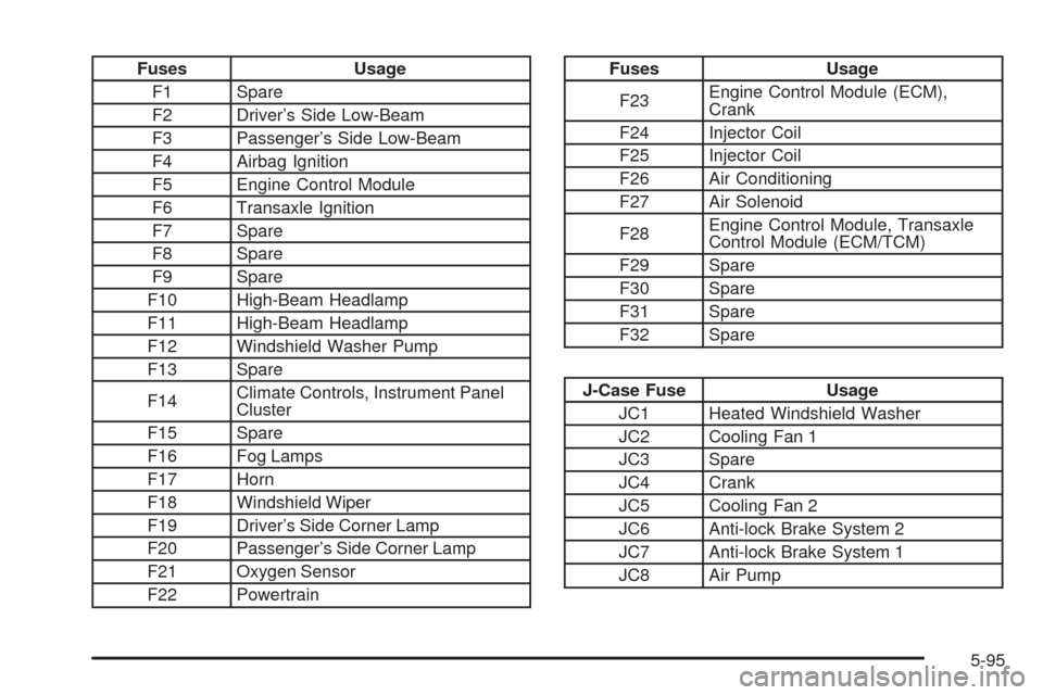
Fuses Usage
F1 Spare
F2 Driver’s Side Low-Beam
F3 Passenger’s Side Low-Beam
F4 Airbag Ignition
F5 Engine Control Module
F6 Transaxle Ignition
F7 Spare
F8 Spare
F9 Spare
F10 High-Beam Headlamp
F11 High-Beam Headlamp
F12 Windshield Washer Pump
F13 Spare
F14Climate Controls, Instrument Panel
Cluster
F15 Spare
F16 Fog Lamps
F17 Horn
F18 Windshield Wiper
F19 Driver’s Side Corner Lamp
F20 Passenger’s Side Corner Lamp
F21 Oxygen Sensor
F22 PowertrainFuses Usage
F23Engine Control Module (ECM),
Crank
F24 Injector Coil
F25 Injector Coil
F26 Air Conditioning
F27 Air Solenoid
F28Engine Control Module, Transaxle
Control Module (ECM/TCM)
F29 Spare
F30 Spare
F31 Spare
F32 Spare
J-Case Fuse Usage
JC1 Heated Windshield Washer
JC2 Cooling Fan 1
JC3 Spare
JC4 Crank
JC5 Cooling Fan 2
JC6 Anti-lock Brake System 2
JC7 Anti-lock Brake System 1
JC8 Air Pump
5-95
Page 398 of 450
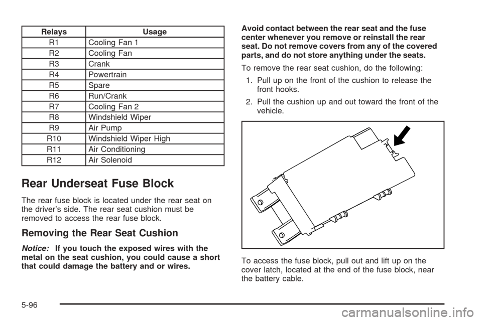
Relays Usage
R1 Cooling Fan 1
R2 Cooling Fan
R3 Crank
R4 Powertrain
R5 Spare
R6 Run/Crank
R7 Cooling Fan 2
R8 Windshield Wiper
R9 Air Pump
R10 Windshield Wiper High
R11 Air Conditioning
R12 Air Solenoid
Rear Underseat Fuse Block
The rear fuse block is located under the rear seat on
the driver’s side. The rear seat cushion must be
removed to access the rear fuse block.
Removing the Rear Seat Cushion
Notice:If you touch the exposed wires with the
metal on the seat cushion, you could cause a short
that could damage the battery and or wires.Avoid contact between the rear seat and the fuse
center whenever you remove or reinstall the rear
seat. Do not remove covers from any of the covered
parts, and do not store anything under the seats.
To remove the rear seat cushion, do the following:
1. Pull up on the front of the cushion to release the
front hooks.
2. Pull the cushion up and out toward the front of the
vehicle.
To access the fuse block, pull out and lift up on the
cover latch, located at the end of the fuse block, near
the battery cable.
5-96
Page 402 of 450
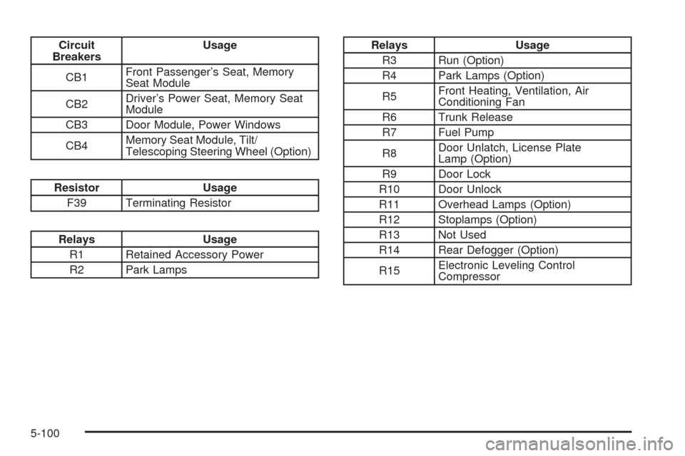
Circuit
BreakersUsage
CB1Front Passenger’s Seat, Memory
Seat Module
CB2Driver’s Power Seat, Memory Seat
Module
CB3 Door Module, Power Windows
CB4Memory Seat Module, Tilt/
Telescoping Steering Wheel (Option)
Resistor Usage
F39 Terminating Resistor
Relays Usage
R1 Retained Accessory Power
R2 Park Lamps
Relays Usage
R3 Run (Option)
R4 Park Lamps (Option)
R5Front Heating, Ventilation, Air
Conditioning Fan
R6 Trunk Release
R7 Fuel Pump
R8Door Unlatch, License Plate
Lamp (Option)
R9 Door Lock
R10 Door Unlock
R11 Overhead Lamps (Option)
R12 Stoplamps (Option)
R13 Not Used
R14 Rear Defogger (Option)
R15Electronic Leveling Control
Compressor
5-100
Page 403 of 450

Capacities and Specications
The following approximate capacities are given in English and metric conversions. SeeRecommended Fluids and
Lubricants on page 6-12for more information.
ApplicationCapacities
English Metric
Air Conditioning Refrigerant 1.43 lbs 0.65 kg
Cooling System 12.9 qt 12.2 L
Engine Oil with Filter 7.5 qt 7.1 L
Fuel Tank 18.5 gal 70.0 L
Transaxle 15.0 qt 14.2 L
Wheel Nut Torque 100 lb ft 140Y
All capacities are approximate. When adding, be sure to ll to the approximate level as recommended in this
manual. Recheck uid level after lling.
Engine Specications
Engine VIN Code Transaxle Spark Plug Gap
4.6L DOHC V8 Y Automatic 0.050 inches (1.27 mm)
4.6L DOHC V8 9 Automatic 0.050 inches (1.27 mm)
5-101
Page 406 of 450

Maintenance Schedule
Introduction
Important: Keep engine oil at the proper level and
change as recommended.
Have you purchased the GM Protection Plan? The Plan
supplements your new vehicle warranties. See your
Warranty and Owner Assistance booklet or your dealer
for details.
Maintenance Requirements
Notice:Maintenance intervals, checks, inspections,
replacement parts, and recommended uids and
lubricants as prescribed in this manual are necessary
to keep your vehicle in good working condition. Any
damage caused by failure to follow scheduled
maintenance may not be covered by warranty.
Your Vehicle and the Environment
Proper vehicle maintenance not only helps to keep your
vehicle in good working condition, but also helps the
environment. All recommended maintenance is
important. Improper vehicle maintenance can even
affect the quality of the air we breathe. Improper uid
levels or the wrong tire ination can increase the level of
emissions from your vehicle. To help protect our
environment, and to keep your vehicle in good condition,
be sure to maintain your vehicle properly.
Using the Maintenance Schedule
We at General Motors want to help you keep your
vehicle in good working condition. But we do not know
exactly how you will drive it. You may drive very
short distances only a few times a week. Or you may
drive long distances all the time in very hot, dusty
weather. You may use your vehicle in making deliveries.
Or you may drive it to work, to do errands, or in many
other ways.
Because of all the different ways people use their
vehicles, maintenance needs vary. You may need more
frequent checks and replacements. So please read
the following and note how you drive. If you have any
questions on how to keep your vehicle in good condition,
see your GM Goodwrench
®dealer.
6-2
Page 407 of 450
This schedule is for vehicles that:
carry passengers and cargo within recommended
limits. You will nd these limits on the Tire and
Loading Information label. SeeLoading Your
Vehicle on page 4-31.
are driven on reasonable road surfaces within legal
driving limits.
use the recommended fuel. SeeGasoline Octane
on page 5-5.
The services inScheduled Maintenance on page 6-4
should be performed when indicated. SeeAdditional
Required Services on page 6-6andMaintenance
Footnotes on page 6-7for further information.
{CAUTION:
Performing maintenance work on a vehicle can
be dangerous. In trying to do some jobs, you
can be seriously injured. Do your own
maintenance work only if you have the
required know-how and the proper tools and
equipment for the job. If you have any doubt,
see your GM Goodwrench
®dealer to have a
qualied technician do the work.Some maintenance services can be complex.
So, unless you are technically qualied and have
the necessary equipment, you should have your
GM Goodwrench
®dealer do these jobs.
When you go to your GM Goodwrench
®dealer for
your service needs, you will know that GM-trained
and supported service technicians will perform the
work using genuine GM parts.
If you want to purchase service information, seeService
Publications Ordering Information on page 7-14.
Owner Checks and Services on page 6-9tells you what
should be checked, when to check it, and what you can
easily do to help keep your vehicle in good condition.
The proper replacement parts, uids, and lubricants to
use are listed inRecommended Fluids and Lubricants
on page 6-12andNormal Maintenance Replacement
Parts on page 6-13. When your vehicle is serviced,
make sure these are used. All parts should be replaced
and all necessary repairs done before you or anyone
else drives the vehicle. We recommend the use of
genuine GM parts.
6-3
Page 411 of 450

Additional Required Services (cont’d)
Service and Miles (Kilometers)25,000
(40 000)50,000
(80 000)75,000
(120 000)100,000
(160 000)125,000
(200 000)150,000
(240 000)
Professional Vehicle Only: Engine
cooling system service (or every
ve years, whichever occurs rst).
An Emission Control Service. See
footnote (j).••
Inspect engine accessory drive belt.
An Emission Control Service. See
footnote (n).•
Maintenance Footnotes
†The U.S. Environmental Protection Agency or the
California Air Resources Board has determined that the
failure to perform this maintenance item will not nullify
the emission warranty or limit recall liability prior to
the completion of the vehicle’s useful life. We, however,
urge that all recommended maintenance services be
performed at the indicated intervals and the
maintenance be recorded.(a)Visually inspect brake lines and hoses for proper
hook-up, binding, leaks, cracks, chang, etc. Inspect
disc brake pads for wear and rotors for surface
condition. Inspect other brake parts, including calipers,
parking brake, etc.
(b)Visually inspect front and rear suspension and
steering system for damaged, loose, or missing parts or
signs of wear. Inspect power steering lines and hoses
for proper hook-up, binding, leaks, cracks, chang, etc.
6-7