sensor CADILLAC ESCALADE EXT 2004 2.G User Guide
[x] Cancel search | Manufacturer: CADILLAC, Model Year: 2004, Model line: ESCALADE EXT, Model: CADILLAC ESCALADE EXT 2004 2.GPages: 478, PDF Size: 3.43 MB
Page 202 of 478

DIC Warnings and Messages
Warning messages are displayed on the DIC to notify
the driver that the status of the vehicle has changed and
that some action may be needed by the driver to
correct the condition. If there is more than one message
that needs to be displayed they will appear one after
another. Some messages may not require immediate
action but you should press the select button to
acknowledge that you received the message and clear it
from the display. Some messages cannot be cleared
from the display because they are more urgent;
these messages require action before they can be
removed from the DIC display. The following are the
possible messages that can be displayed and some
information about them.
CHANGE ENGINE OIL
This message is displayed when the engine oil needs to
be changed. SeeGM Oil Life Systempreviously in
this section for information on how to reset the message.
This message will clear itself after 10 seconds until
the next ignition cycle.
OIL LIFE RESET
This message will appear on the display for about
10 seconds after resetting the change engine oil
message.
OIL PRESSURE LOW
If low oil pressure levels occur, this message will be
displayed on the DIC and a chime will sound. Stop the
vehicle as soon as safely possible and do not operate
it until the cause of the low oil pressure has been
corrected. Check your oil as soon as possible and have
your vehicle serviced.
CHECK OIL LEVEL
If the oil level in the vehicle is low, this message will
appear on the DIC. Check the oil level and correct it as
necessary. You may need to let the vehicle cool or
warm up and cycle the ignition to be sure this message
will clear. Once the problem is corrected, pressing
the select button will clear this message from the DIC
display. This message will clear itself after 10 seconds
until the next ignition cycle.
LOW COOLANT LEVEL
If your vehicle has a low coolant sensor and the engine
coolant level is low, this message will appear on the
DIC. Adding coolant will clear the message. This
message will clear itself after 10 seconds until the next
ignition cycle.
3-60
Page 209 of 478

CHECK TIRE PRESSURE
If a low tire pressure is detected in any of the vehicle's
tires, this message will appear on the DIC. Press
the select button to clear it from the DIC display. It will
appear at each ignition cycle until the tires are
in¯ated to the correct in¯ation pressure.
See
Tires on page 5-63for more information on tires
and the correct in¯ation pressures.
SERVICE TIRE MONITOR
This message will be displayed if any of the tire monitor
sensors have malfunctioned, or if the tire monitor
sensors have not been programmed, or if the
recommended tire pressures are not programmed.
Press the select button to clear it from the DIC display.
Audio System(s)
Notice:Before you add any sound equipment to
your vehicle ± like a tape player, CB radio, mobile
telephone or two-way radio ± be sure you can
add what you want. If you can, it's very important to
do it properly. Added sound equipment may
interfere with the operation of your vehicle's engine,
radio or other systems, and even damage them.
Your vehicle's systems may interfere with the
operation of sound equipment that has been added
improperly.
So, before adding sound equipment, check with
your dealer and be sure to check federal rules
covering mobile radio and telephone units.
Your audio system has been designed to operate easily
and to give years of listening pleasure. You will get
the most enjoyment out of it if you acquaint yourself with
it ®rst. Figure out which radio you have in your vehicle,
®nd out what your audio system can do and how to
operate all of its controls to be sure you're getting the
most out of the advanced engineering that went into it.
Your vehicle has a feature called Retained Accessory
Power (RAP). With RAP, you can play your audio
system even after the ignition is turned off. See
ªRetained Accessory Power (RAP)º under
Ignition
Positions on page 2-30.
3-67
Page 382 of 478

Tire Pressure Monitor System
The Tire Pressure Monitor (TPM) system uses radio
and sensor technology to check tire pressure levels. If
your vehicle has this feature, sensors are mounted
on each tire and wheel assembly, except the spare tire.
The TPM sensors transmit tire pressure readings to
a receiver located in the vehicle.
When a low tire pressure condition is detected, the TPM
system will display the CHECK TIRE PRESSURE
warning message on the Driver Information Center
(DIC); and at the same time illuminate the low tire
pressure warning symbol. For additional information and
details about the DIC operation and displays see DIC
Operation and Displays on page 3-49andDIC Warnings
and Messages on page 3-60.
When the tire pressure
monitoring system warning
light is lit, one or more
of your tires is signi®cantly
under-in¯ated.You should stop and check your tires as soon as
possible, and in¯ate them to the proper pressure as
indicated on the vehicle's tire information placard.
Driving on a signi®cantly under-in¯ated tire causes the
tire to overheat and can lead to tire failure.
Under-in¯ation also reduces fuel efficiency and tire tread
life, and may affect the vehicle's handling and stopping
ability. Each tire, including the spare, should be
checked monthly when cold and set to the
recommended in¯ation pressure as speci®ed in the
vehicle placard and owner's manual.
The Certi®cation/Tire label or the Tire and Loading
Information label (tire information placard) shows the
size of your vehicle's original tires and the correct
in¯ation pressure for your vehicle's tires when they are
cold. SeeIn¯ation - Tire Pressure on page 5-71. For
the location of the tire and loading information label, see
Loading Your Vehicle on page 4-47.
Your vehicle's TPM system can alert you about a low
tire pressure condition but it does not replace normal tire
maintenance. See
Tire Inspection and Rotation on
page 5-74andTires on page 5-63.
Notice:Do not use a tire sealant if your vehicle is
equipped with Tire Pressure Monitors. The liquid
sealant can damage the tire pressure monitor
sensors.
5-72
Page 383 of 478

TPM Sensor Identi®cation Codes
Each TPM sensor has a unique identi®cation code. Any
time you rotate your vehicle's tires or replace one or
more of the TPM sensors, the identi®cation codes
will need to be matched to the new tire/wheel position.
Each tire/wheel position is matched to a sensor, by
increasing or decreasing the tire's air pressure.
The sensors are matched to the tire/wheel positions in
the following order: left front (LF); right front (RF);
right rear (RR) and left rear (LR).
You will have one minute to match the ®rst tire/wheel
position, and ®ve minutes overall to match all four
tire/wheel positions. If it takes longer than one minute,
to match the ®rst tire and wheel, or more than ®ve
minutes to match all four tire and wheel positions the
matching process stops and you will need to start over.
The TPM sensor matching process is outlined below:
1. Set the Parking brake.
2. Turn the ignition switch to RUN with the engine off.3. Turn the exterior lamp switch from ªOffº to ªOnº
four times within 3 seconds. A double horn chirp
will sound and the TPM low tire warning light
will begin to ¯ash. The double horn chirp and
¯ashing TPM warning light indicate that the TPM
matching process has started. The TPM warning
light should continue ¯ashing throughout the
matching procedure. The SERVICE TIRE
MONITOR message will be displayed on the Driver
Information Center (DIC).
4. Start with the left (driver's side) front tire.
5. Remove the valve cap from the valve cap stem.
Activate the TPM sensor by increasing or
decreasing the tire's air pressure for 10 seconds,
then stop and listen for a single horn chirp.
The single horn chirp should sound within
15 seconds, con®rming that the sensor identi®cation
code has been matched to this tire and wheel
position. If you do not hear the con®rming single
horn chirp, you will need to start over with step
number one. To let air-pressure out of a tire you can
use the pointy end of the valve cap, a pencil-style
air pressure gage or a key.
5-73
Page 384 of 478

6. Proceed to the right (passenger's side) front tire,
and repeat the procedure in step 5.
7. Proceed to the right (passenger's side) rear tire,
and repeat the procedure in step 5.
8. Proceed to the left (driver's side) rear tire, and
repeat the procedure in step 5.
9. After hearing the con®rming horn chirp for the left
rear tire, check to see if the TPM warning light is
still ¯ashing. If yes, turn the ignition switch to OFF.
10. Set all four tires to the recommended air pressure
level as indicated on the Certi®cation/Tire label or
the Tire and Loading Information label.
11. Put the valve caps back on the valve stems
The spare tire does not have a TPM sensor. If you
replace one of the road tires with the spare, the CHECK
TIRE PRESSURE message will be displayed on the
DIC screen. This message should go off once you
re-install the road tire containing the TPM sensor. The
SERVICE TIRE MONITOR message is displayed
when the TPM system is malfunctioning. One or more
missing or inoperable TPM sensors will cause the
service tire monitor message to be displayed. See your
dealer for service.Federal Communications Commission and
Industry and Science Canada
The TPM system operates on a radio frequency subject
to Federal Communications Commission (FCC) Rules
and with Industry and Science Canada.
This device complies with Part 15 of the FCC Rules and
with RSS-210 of Industry and Science Canada.
Operation is subject to the following two conditions: (1)
This device may not cause harmful interference, and
(2) this device must accept any interference received
including interference that may cause undesired
operation of the device.
Changes or modi®cations to this system by other than
an authorized service facility could void authorization to
use this equipment.
Tire Inspection and Rotation
Tires should be rotated every 5,000 to 8,000 miles
(8 000 to 13 000 km).
Any time you notice unusual wear, rotate your tires as
soon as possible and check wheel alignment. Also
check for damaged tires or wheels. See
When It Is Time
for New Tires on page 5-76andWheel Replacement
on page 5-80for more information.
5-74
Page 385 of 478

Make sure the spare tire is stored securely. Push, pull,
and then try to rotate or turn the tire. If it moves,
use the ratchet/wheel wrench to tighten the cable. See
Changing a Flat Tire on page 5-83.
The purpose of regular rotation is to achieve more
uniform wear for all tires on the vehicle. The ®rst rotation
is the most important. See
Scheduled Maintenance
on page 6-4.
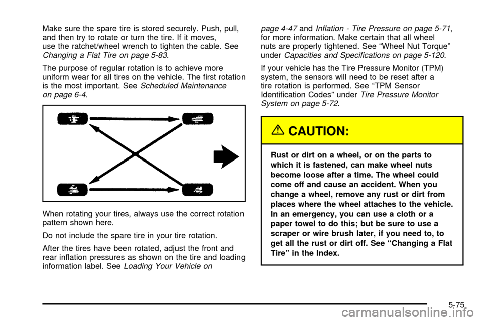
When rotating your tires, always use the correct rotation
pattern shown here.
Do not include the spare tire in your tire rotation.
After the tires have been rotated, adjust the front and
rear in¯ation pressures as shown on the tire and loading
information label. See
Loading Your Vehicle onpage 4-47
andIn¯ation - Tire Pressure on page 5-71,
for more information. Make certain that all wheel
nuts are properly tightened. See ªWheel Nut Torqueº
under
Capacities and Speci®cations on page 5-120.
If your vehicle has the Tire Pressure Monitor (TPM)
system, the sensors will need to be reset after a
tire rotation is performed. See ªTPM Sensor
Identi®cation Codesº under
Tire Pressure Monitor
System on page 5-72.
{CAUTION:
Rust or dirt on a wheel, or on the parts to
which it is fastened, can make wheel nuts
become loose after a time. The wheel could
come off and cause an accident. When you
change a wheel, remove any rust or dirt from
places where the wheel attaches to the vehicle.
In an emergency, you can use a cloth or a
paper towel to do this; but be sure to use a
scraper or wire brush later, if you need to, to
get all the rust or dirt off. See ªChanging a Flat
Tireº in the Index.
5-75
Page 427 of 478

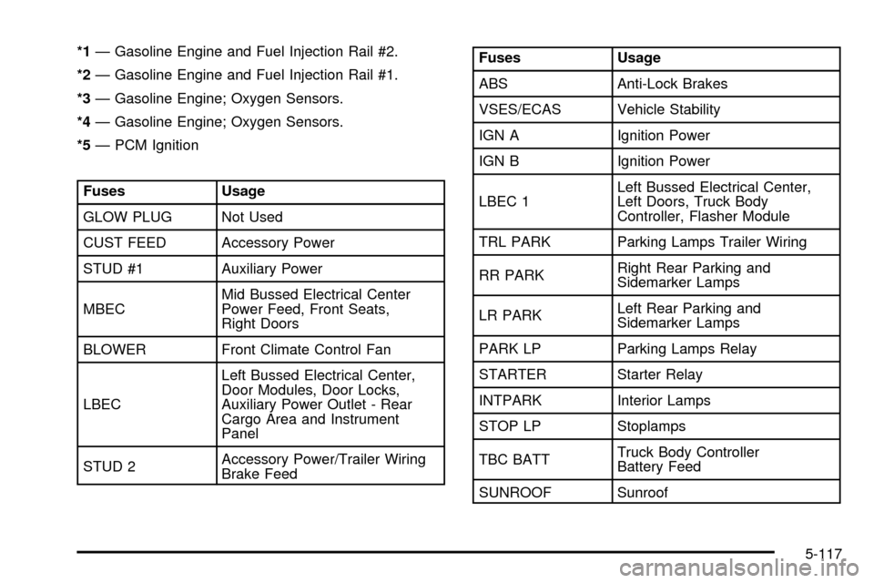
*1Ð Gasoline Engine and Fuel Injection Rail #2.
*2Ð Gasoline Engine and Fuel Injection Rail #1.
*3Ð Gasoline Engine; Oxygen Sensors.
*4Ð Gasoline Engine; Oxygen Sensors.
*5Ð PCM Ignition
Fuses Usage
GLOW PLUG Not Used
CUST FEED Accessory Power
STUD #1 Auxiliary Power
MBECMid Bussed Electrical Center
Power Feed, Front Seats,
Right Doors
BLOWER Front Climate Control Fan
LBECLeft Bussed Electrical Center,
Door Modules, Door Locks,
Auxiliary Power Outlet - Rear
Cargo Area and Instrument
Panel
STUD 2Accessory Power/Trailer Wiring
Brake Feed
Fuses Usage
ABS Anti-Lock Brakes
VSES/ECAS Vehicle Stability
IGN A Ignition Power
IGN B Ignition Power
LBEC 1Left Bussed Electrical Center,
Left Doors, Truck Body
Controller, Flasher Module
TRL PARK Parking Lamps Trailer Wiring
RR PARKRight Rear Parking and
Sidemarker Lamps
LR PARKLeft Rear Parking and
Sidemarker Lamps
PARK LP Parking Lamps Relay
STARTER Starter Relay
INTPARK Interior Lamps
STOP LP Stoplamps
TBC BATTTruck Body Controller
Battery Feed
SUNROOF Sunroof
5-117
Page 428 of 478

Fuses Usage
SEO B2 Off-Road Lamps
4WSVent Solenoid
Canister/Quadrasteer Module
Power
RR HVAC Rear Climate Control
AUX PWRAuxiliary Power
Outlet - Console
IGN 1 Ignition Relay
PCM 1 Powertrain Control Module
ETC/ECMElectronic Throttle Control,
Electronic Brake Controller
INJ 1Ignition Coil, Fuel
Injectors - Bank 1
INJ 2Ignition Coil, Fuel
Injectors - Bank 2
IGN EInstrument Panel Cluster,
Air Conditioning Relay,
Turn Signal/Hazard Switch,
Starter Relay
RTD Ride Control
TRL B/U Backup Lamps Trailer WiringFuses Usage
PCM BPowertrain Control Module,
Fuel Pump
F/PMP Fuel Pump (Relay)
O2A Oxygen Sensors
B/U LPBack-up Lamps, Automatic
Transmission Shift Lock Control
System
RR DEFOG Rear Window Defogger
HDLP-HI Headlamp High Beam Relay
PRIME Not Used
O2B Oxygen Sensors
SIRSupplemental In¯atable Restraint
System
FRT PARKFront Parking Lamps,
Sidemarker Lamps
DRL Daytime Running Lamps (Relay)
SEO IGN Rear Defog Relay
TBC IGN1 Truck Body Controller Ignition
HI HDLP - LT High Beam Headlamp - Left
5-118