remove CADILLAC ESCALADE EXT 2004 2.G Workshop Manual
[x] Cancel search | Manufacturer: CADILLAC, Model Year: 2004, Model line: ESCALADE EXT, Model: CADILLAC ESCALADE EXT 2004 2.GPages: 478, PDF Size: 3.43 MB
Page 371 of 478
Center High-Mounted
Stoplamp (CHMSL)
It is recommended that this component be replaced as
a unit by your dealer.
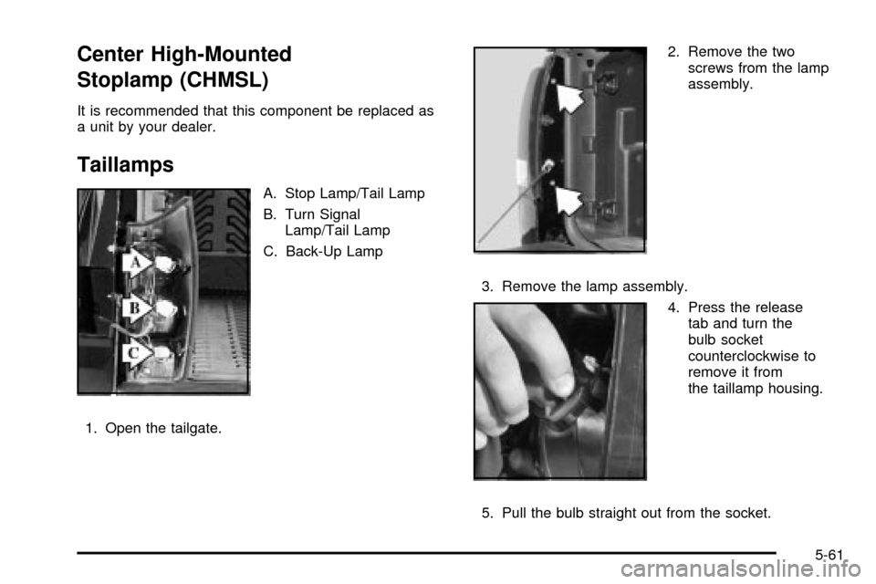
Taillamps
A. Stop Lamp/Tail Lamp
B. Turn Signal
Lamp/Tail Lamp
C. Back-Up Lamp
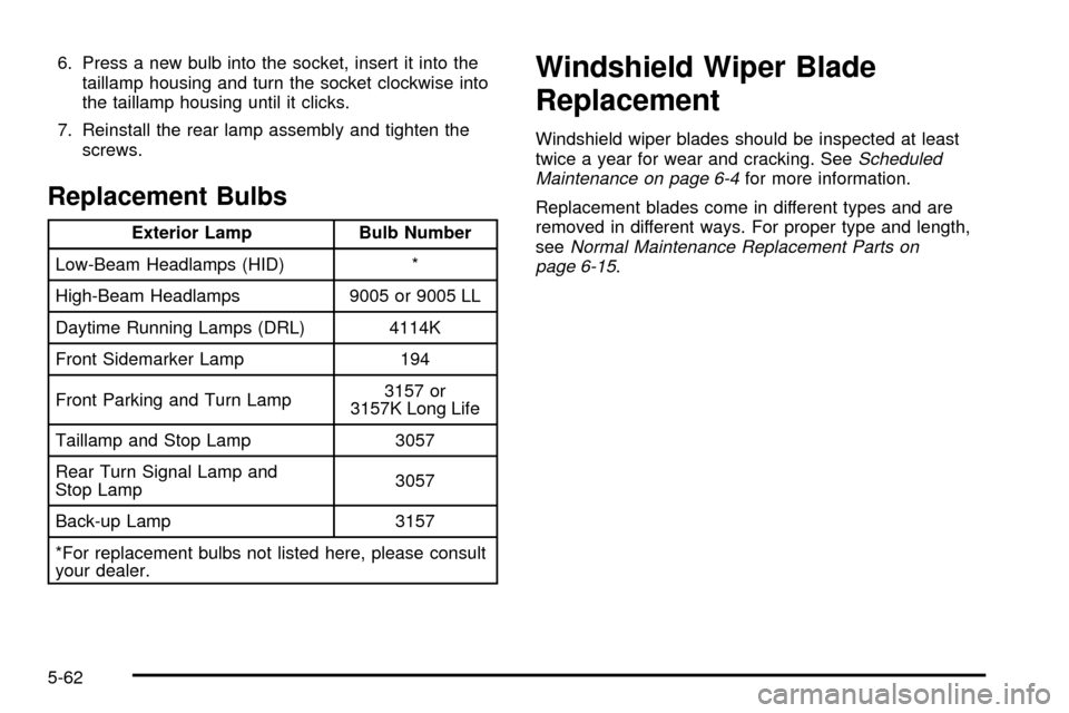
1. Open the tailgate.2. Remove the two
screws from the lamp
assembly.
3. Remove the lamp assembly.
4. Press the release
tab and turn the
bulb socket
counterclockwise to
remove it from
the taillamp housing.
5. Pull the bulb straight out from the socket.
5-61
Page 372 of 478
6. Press a new bulb into the socket, insert it into the
taillamp housing and turn the socket clockwise into
the taillamp housing until it clicks.
7. Reinstall the rear lamp assembly and tighten the
screws.
Replacement Bulbs
Exterior Lamp Bulb Number
Low-Beam Headlamps (HID) *
High-Beam Headlamps 9005 or 9005 LL
Daytime Running Lamps (DRL) 4114K
Front Sidemarker Lamp 194
Front Parking and Turn Lamp3157 or
3157K Long Life
Taillamp and Stop Lamp 3057
Rear Turn Signal Lamp and
Stop Lamp3057
Back-up Lamp 3157
*For replacement bulbs not listed here, please consult
your dealer.
Windshield Wiper Blade
Replacement
Windshield wiper blades should be inspected at least
twice a year for wear and cracking. SeeScheduled
Maintenance on page 6-4for more information.
Replacement blades come in different types and are
removed in different ways. For proper type and length,
see
Normal Maintenance Replacement Parts on
page 6-15.
5-62
Page 381 of 478

In¯ation - Tire Pressure
The tire and loading information label, shows the correct
in¯ation pressures for your tires when they're cold.
ªColdº means your vehicle has been sitting for at least
three hours or driven no more than 1 mile (1.6 km). See
Loading Your Vehicle on page 4-47, for the location
of your vehicle's tire and loading information label.
Notice:Don't let anyone tell you that underin¯ation
or overin¯ation is all right. It's not. If your tires
don't have enough air (underin¯ation), you can get
the following:
·Too much ¯exing
·Too much heat
·Tire overloading
·Bad wear
·Bad handling
·Bad fuel economy
If your tires have too much air (overin¯ation), you
can get the following:
·Unusual wear
·Bad handling
·Rough ride
·Needless damage from road hazards
When to Check
Check your tires once a month or more.
Also, check the tire pressure of the spare tire.
How to Check
Use a good quality pocket-type gage to check tire
pressure. You can't tell if your tires are properly in¯ated
simply by looking at them. Radial tires may look
properly in¯ated even when they're underin¯ated. Check
the tire's in¯ation pressure when the tires are cold.
cold means your vehicle has been sitting for at least
three hours or driven no more than 1 mile (1.6 km).
Remove the valve cap from the tire valve stem. Press
the tire gage ®rmly onto the valve to get a pressure
measurement. If the cold tire in¯ation pressure matches
the recommended pressure on the tire and loading
information label, no further adjustment is necessary. If
the pressure is low, add air until you reach the
recommended amount.
If you over®ll the tire, release air by pushing on the
metal stem in the center of the tire valve. Recheck the
tire pressure with the tire gage.
Be sure to put the valve caps back on the valve stems.
They help prevent leaks by keeping out dirt and
moisture.
5-71
Page 383 of 478

TPM Sensor Identi®cation Codes
Each TPM sensor has a unique identi®cation code. Any
time you rotate your vehicle's tires or replace one or
more of the TPM sensors, the identi®cation codes
will need to be matched to the new tire/wheel position.
Each tire/wheel position is matched to a sensor, by
increasing or decreasing the tire's air pressure.
The sensors are matched to the tire/wheel positions in
the following order: left front (LF); right front (RF);
right rear (RR) and left rear (LR).
You will have one minute to match the ®rst tire/wheel
position, and ®ve minutes overall to match all four
tire/wheel positions. If it takes longer than one minute,
to match the ®rst tire and wheel, or more than ®ve
minutes to match all four tire and wheel positions the
matching process stops and you will need to start over.
The TPM sensor matching process is outlined below:
1. Set the Parking brake.
2. Turn the ignition switch to RUN with the engine off.3. Turn the exterior lamp switch from ªOffº to ªOnº
four times within 3 seconds. A double horn chirp
will sound and the TPM low tire warning light
will begin to ¯ash. The double horn chirp and
¯ashing TPM warning light indicate that the TPM
matching process has started. The TPM warning
light should continue ¯ashing throughout the
matching procedure. The SERVICE TIRE
MONITOR message will be displayed on the Driver
Information Center (DIC).
4. Start with the left (driver's side) front tire.
5. Remove the valve cap from the valve cap stem.
Activate the TPM sensor by increasing or
decreasing the tire's air pressure for 10 seconds,
then stop and listen for a single horn chirp.
The single horn chirp should sound within
15 seconds, con®rming that the sensor identi®cation
code has been matched to this tire and wheel
position. If you do not hear the con®rming single
horn chirp, you will need to start over with step
number one. To let air-pressure out of a tire you can
use the pointy end of the valve cap, a pencil-style
air pressure gage or a key.
5-73
Page 385 of 478
Make sure the spare tire is stored securely. Push, pull,
and then try to rotate or turn the tire. If it moves,
use the ratchet/wheel wrench to tighten the cable. See
Changing a Flat Tire on page 5-83.
The purpose of regular rotation is to achieve more
uniform wear for all tires on the vehicle. The ®rst rotation
is the most important. See
Scheduled Maintenance
on page 6-4.
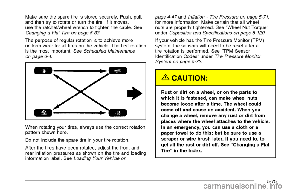
When rotating your tires, always use the correct rotation
pattern shown here.
Do not include the spare tire in your tire rotation.
After the tires have been rotated, adjust the front and
rear in¯ation pressures as shown on the tire and loading
information label. See
Loading Your Vehicle onpage 4-47
andIn¯ation - Tire Pressure on page 5-71,
for more information. Make certain that all wheel
nuts are properly tightened. See ªWheel Nut Torqueº
under
Capacities and Speci®cations on page 5-120.
If your vehicle has the Tire Pressure Monitor (TPM)
system, the sensors will need to be reset after a
tire rotation is performed. See ªTPM Sensor
Identi®cation Codesº under
Tire Pressure Monitor
System on page 5-72.
{CAUTION:
Rust or dirt on a wheel, or on the parts to
which it is fastened, can make wheel nuts
become loose after a time. The wheel could
come off and cause an accident. When you
change a wheel, remove any rust or dirt from
places where the wheel attaches to the vehicle.
In an emergency, you can use a cloth or a
paper towel to do this; but be sure to use a
scraper or wire brush later, if you need to, to
get all the rust or dirt off. See ªChanging a Flat
Tireº in the Index.
5-75
Page 391 of 478

Used Replacement Wheels
{CAUTION:
Putting a used wheel on your vehicle is
dangerous. You can't know how it's been used
or how far it's been driven. It could fail
suddenly and cause a crash. If you have to
replace a wheel, use a new GM original
equipment wheel.
Tire Chains
{CAUTION:
Don't use tire chains. There's not enough
clearance. Tire chains used on a vehicle
without the proper amount of clearance can
cause damage to the brakes, suspension or
other vehicle parts. The area damaged by the
tire chains could cause you to lose control of
your vehicle and you or others may be injured
in a crash. Use another type of traction device
only if its manufacturer recommends it for use
on your vehicle and tire size combination and
road conditions. Follow that manufacturer's
instructions. To help avoid damage to your
vehicle, drive slowly, readjust or remove the
device if it's contacting your vehicle, and
don't spin your wheels. If you do ®nd traction
devices that will ®t, install them on the
rear tires.
5-81
Page 392 of 478
If a Tire Goes Flat
It's unusual for a tire to ªblowoutº while you're driving,
especially if you maintain your tires properly. If air goes
out of a tire, it's much more likely to leak out slowly.
But if you should ever have a ªblowout,º here are a few
tips about what to expect and what to do:
If a front tire fails, the ¯at tire will create a drag that
pulls the vehicle toward that side. Take your foot off the
accelerator pedal and grip the steering wheel ®rmly.
Steer to maintain lane position, and then gently brake to
a stop well out of the traffic lane.
A rear blowout, particularly on a curve, acts much like a
skid and may require the same correction you'd use
in a skid. In any rear blowout, remove your foot from the
accelerator pedal. Get the vehicle under control by
steering the way you want the vehicle to go. It may be
very bumpy and noisy, but you can still steer. Gently
brake to a stop, well off the road if possible.{CAUTION:
Lifting a vehicle and getting under it to do
maintenance or repairs is dangerous without
the appropriate safety equipment and training.
The jack provided with your vehicle is
designed only for changing a ¯at tire. If it is
used for anything else, you or others could be
badly injured or killed if the vehicle slips off
the jack. Use the jack provided with your
vehicle only for changing a ¯at tire.
If a tire goes ¯at, the next part shows how to use your
jacking equipment to change a ¯at tire safely.
5-82
Page 394 of 478
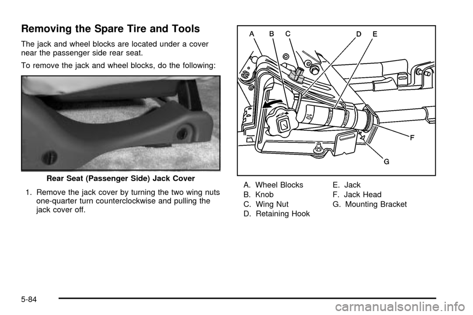
Removing the Spare Tire and Tools
The jack and wheel blocks are located under a cover
near the passenger side rear seat.
To remove the jack and wheel blocks, do the following:
1. Remove the jack cover by turning the two wing nuts
one-quarter turn counterclockwise and pulling the
jack cover off.A. Wheel Blocks
B. Knob
C. Wing Nut
D. Retaining HookE. Jack
F. Jack Head
G. Mounting Bracket Rear Seat (Passenger Side) Jack Cover
5-84
Page 395 of 478
2. Release the jack (E) from the mounting bracket (G)
by turning the knob (B) on the jack counterclockwise
to lower the jack head (F) from the mounting
bracket.
3. Remove the wheel blocks (A) attached to the
jack (E) by turning the wing nut (C)
counterclockwise. Place the wheel blocks where
needed as indicated in the previous Caution.
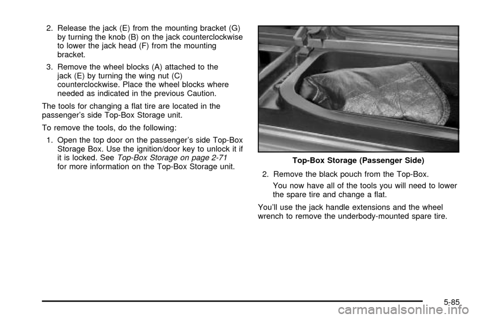
The tools for changing a ¯at tire are located in the
passenger's side Top-Box Storage unit.
To remove the tools, do the following:
1. Open the top door on the passenger's side Top-Box
Storage Box. Use the ignition/door key to unlock it if
it is locked. See
Top-Box Storage on page 2-71for more information on the Top-Box Storage unit.
2. Remove the black pouch from the Top-Box.
You now have all of the tools you will need to lower
the spare tire and change a ¯at.
You'll use the jack handle extensions and the wheel
wrench to remove the underbody-mounted spare tire.Top-Box Storage (Passenger Side)
5-85
Page 396 of 478
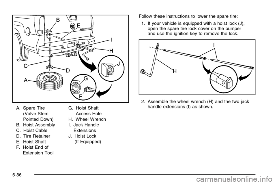
A. Spare Tire
(Valve Stem
Pointed Down)
B. Hoist Assembly
C. Hoist Cable
D. Tire Retainer
E. Hoist Shaft
F. Hoist End of
Extension ToolG. Hoist Shaft
Access Hole
H. Wheel Wrench
I. Jack Handle
Extensions
J. Hoist Lock
(If Equipped)Follow these instructions to lower the spare tire:
1. If your vehicle is equipped with a hoist lock (J),
open the spare tire lock cover on the bumper
and use the ignition key to remove the lock.
2. Assemble the wheel wrench (H) and the two jack
handle extensions (I) as shown.
5-86