run CADILLAC SRX 2012 2.G Repair Manual
[x] Cancel search | Manufacturer: CADILLAC, Model Year: 2012, Model line: SRX, Model: CADILLAC SRX 2012 2.GPages: 502, PDF Size: 6.23 MB
Page 368 of 502

Black plate (36,1)Cadillac SRX Owner Manual (Include Mex) - 2012
10-36 Vehicle Care
Daytime Running Lamp (DRL)
(Up-Level)
1. From the back side of theheadlamp assembly, remove the
bottom cap to replace the
DRL bulb.
2. Disconnect electrical connector.
3. Remove the DRL bulb socket from the headlamp assembly. 4. Replace the bulb in the bulb
socket.
5. Install the bulb socket in the headlamp assembly.
6. Connect the electrical connector.
7. Install the cap with the down arrow pointing down in the back
of the headlamp assembly.
8. For driver side, reinstall the underhood electrical center
cover by latching three clips.
9. For passenger side, reinstall the air filter/cleaner assembly
base by pushing to seat .
Verify the base is seated
securely, then install the engine
air filter/cleaner assembly.
Front Turn Signal Lamp
(Base and Up-Level)
To replace the Front Turn
Signal Lamp:
1. Remove the turn signal lampbulb socket from the headlamp
assembly.
2. Remove the turn signal lamp bulb from the socket.
3. Replace the bulb in the bulb socket.
4. Install the bulb socket in the headlamp assembly.
5. For driver side, reinstall the underhood electrical center
cover by latching three clips.
6. For passenger side, reinstall the air filter/cleaner assembly
base by pushing to seat .
Verify the base is seated
securely, then install the engine
air filter/cleaner assembly.
Page 372 of 502

Black plate (40,1)Cadillac SRX Owner Manual (Include Mex) - 2012
10-40 Vehicle Care
License Plate Lamp
To replace one of these bulbs:
1. Open the liftgate. SeeLiftgate
on page 2‑14 for more
information.
Passenger Side Shown,
Driver Side Similar
2. Push the left end of the lamp assembly towards the right.
3. Turn the lamp assembly down to remove from liftgate.
A. Bulb Socket
B. Bulb
C. Lamp Assembly
4. Turn the bulb socket (A) counterclockwise to remove from
lamp assembly (C).
5. Pull the bulb (B) straight out of the bulb socket.
6. Push the replacement bulb straight into the bulb socket and
turn the bulb socket clockwise to
install into lamp assembly.
7. Turn the lamp assembly into the liftgate engaging the
clip side first.
8. Push on the lamp side opposite the clip until the lamp assembly
snaps into place.
Replacement Bulbs
Exterior Lamp Bulb
Number
Back‐up Lamp 921
Daytime
Running Lamp 7443
Fog Lamp H10
Headlamp
High-Beam 9005
Headlamp
Low-Beam H10
License Plate Lamp 194LL
Turn Signal Front 7440
Tail/Turn
Signal Rear 7440
For replacement bulbs not listed
here, contact your dealer.
Page 375 of 502
Black plate (43,1)Cadillac SRX Owner Manual (Include Mex) - 2012
Vehicle Care 10-43
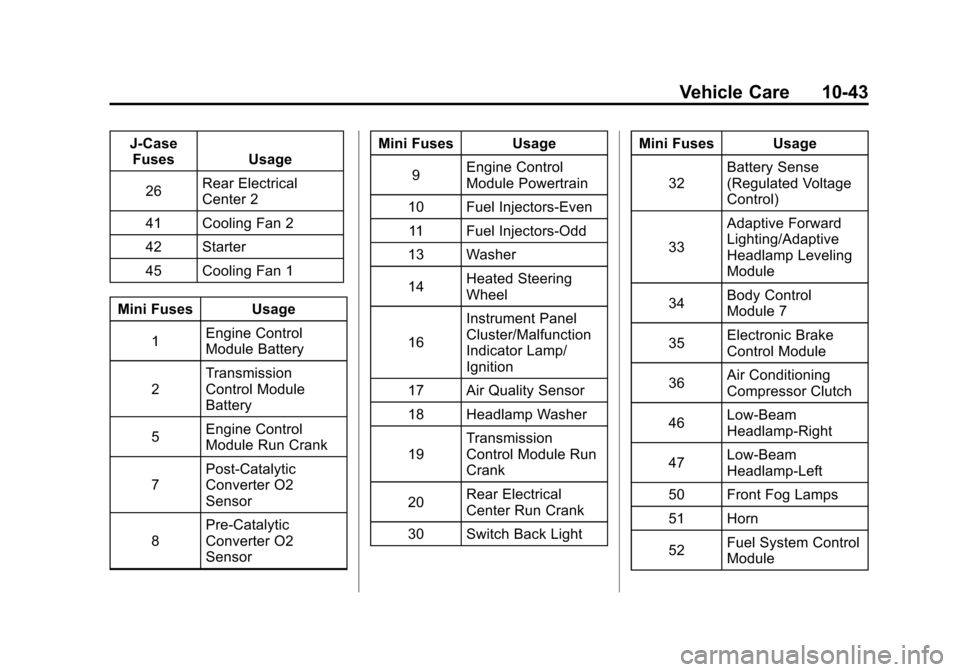
J-CaseFuses Usage
26 Rear Electrical
Center 2
41 Cooling Fan 2
42 Starter
45 Cooling Fan 1
Mini Fuses Usage 1 Engine Control
Module Battery
2 Transmission
Control Module
Battery
5 Engine Control
Module Run Crank
7 Post-Catalytic
Converter O2
Sensor
8 Pre-Catalytic
Converter O2
Sensor Mini Fuses Usage
9 Engine Control
Module Powertrain
10 Fuel Injectors-Even 11 Fuel Injectors-Odd
13 Washer
14 Heated Steering
Wheel
16 Instrument Panel
Cluster/Malfunction
Indicator Lamp/
Ignition
17 Air Quality Sensor
18 Headlamp Washer
19 Transmission
Control Module Run
Crank
20 Rear Electrical
Center Run Crank
30 Switch Back Light Mini Fuses Usage
32 Battery Sense
(Regulated Voltage
Control)
33 Adaptive Forward
Lighting/Adaptive
Headlamp Leveling
Module
34 Body Control
Module 7
35 Electronic Brake
Control Module
36 Air Conditioning
Compressor Clutch
46 Low-Beam
Headlamp‐Right
47 Low-Beam
Headlamp‐Left
50 Front Fog Lamps
51 Horn
52 Fuel System Control
Module
Page 376 of 502
Black plate (44,1)Cadillac SRX Owner Manual (Include Mex) - 2012
10-44 Vehicle Care
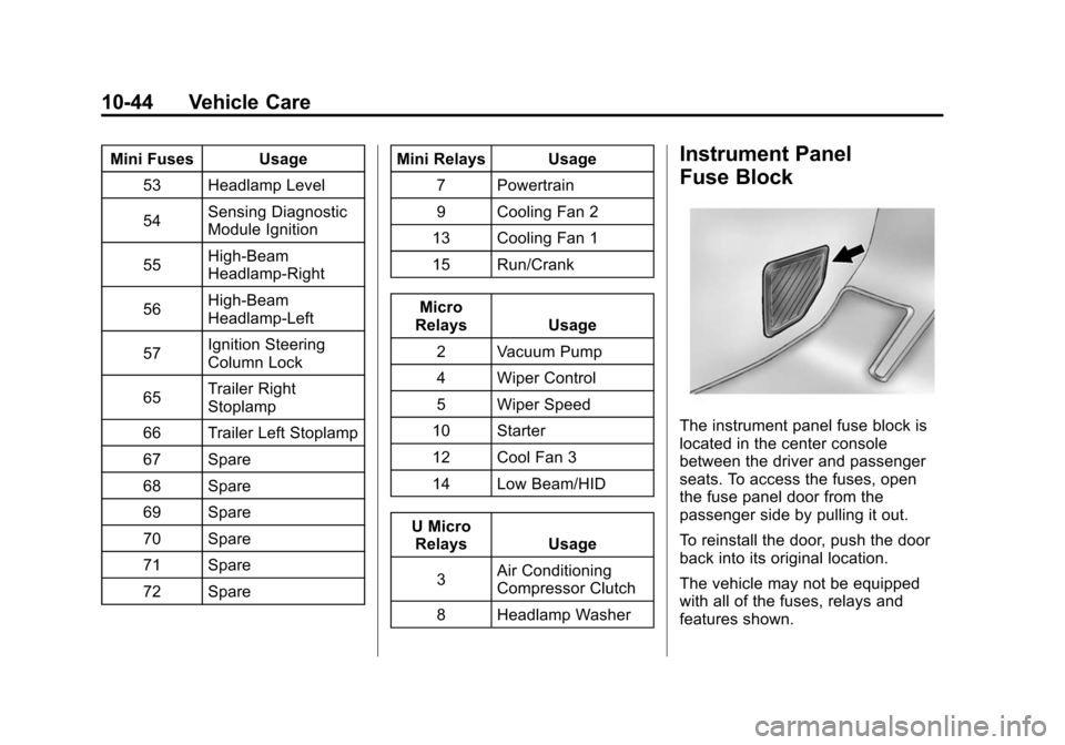
Mini Fuses Usage53 Headlamp Level
54 Sensing Diagnostic
Module Ignition
55 High-Beam
Headlamp-Right
56 High-Beam
Headlamp-Left
57 Ignition Steering
Column Lock
65 Trailer Right
Stoplamp
66 Trailer Left Stoplamp
67 Spare
68 Spare
69 Spare
70 Spare
71 Spare
72 Spare Mini Relays Usage
7 Powertrain
9 Cooling Fan 2
13 Cooling Fan 1
15 Run/Crank
Micro
Relays Usage
2 Vacuum Pump
4 Wiper Control
5 Wiper Speed
10 Starter
12 Cool Fan 3
14 Low Beam/HID
U Micro Relays Usage
3 Air Conditioning
Compressor Clutch
8 Headlamp WasherInstrument Panel
Fuse Block
The instrument panel fuse block is
located in the center console
between the driver and passenger
seats. To access the fuses, open
the fuse panel door from the
passenger side by pulling it out.
To reinstall the door, push the door
back into its original location.
The vehicle may not be equipped
with all of the fuses, relays and
features shown.
Page 380 of 502
Black plate (48,1)Cadillac SRX Owner Manual (Include Mex) - 2012
10-48 Vehicle Care
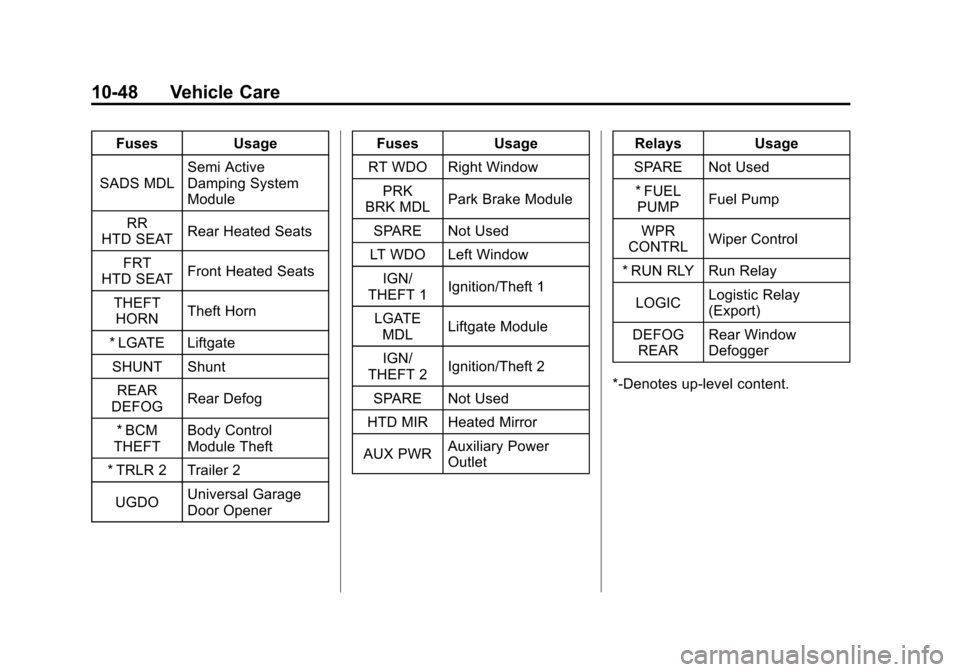
FusesUsage
SADS MDL Semi Active
Damping System
Module
RR
HTD SEAT Rear Heated Seats
FRT
HTD SEAT Front Heated Seats
THEFT HORN Theft Horn
* LGATE Liftgate SHUNT Shunt REAR
DEFOG Rear Defog
* BCM
THEFT Body Control
Module Theft
* TRLR 2 Trailer 2
UGDO Universal Garage
Door Opener Fuses
Usage
RT WDO Right Window PRK
BRK MDL Park Brake Module
SPARE Not Used
LT WDO Left Window
IGN/
THEFT 1 Ignition/Theft 1
LGATE MDL Liftgate Module
IGN/
THEFT 2 Ignition/Theft 2
SPARE Not Used
HTD MIR Heated Mirror
AUX PWR Auxiliary Power
Outlet Relays
Usage
SPARE Not Used * FUEL PUMP Fuel Pump
WPR
CONTRL Wiper Control
* RUN RLY Run Relay
LOGIC Logistic Relay
(Export)
DEFOG REAR Rear Window
Defogger
*‐Denotes up‐level content.
Page 394 of 502
Black plate (62,1)Cadillac SRX Owner Manual (Include Mex) - 2012
10-62 Vehicle Care
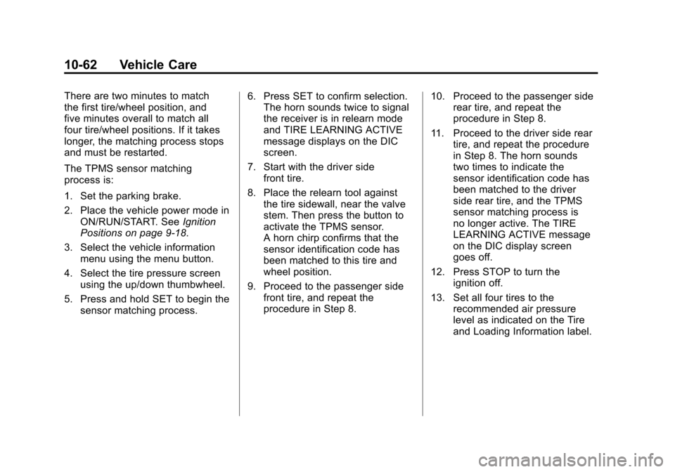
There are two minutes to match
the first tire/wheel position, and
five minutes overall to match all
four tire/wheel positions. If it takes
longer, the matching process stops
and must be restarted.
The TPMS sensor matching
process is:
1. Set the parking brake.
2. Place the vehicle power mode inON/RUN/START. See Ignition
Positions on page 9‑18.
3. Select the vehicle information menu using the menu button.
4. Select the tire pressure screen using the up/down thumbwheel.
5. Press and hold SET to begin the sensor matching process. 6. Press SET to confirm selection.
The horn sounds twice to signal
the receiver is in relearn mode
and TIRE LEARNING ACTIVE
message displays on the DIC
screen.
7. Start with the driver side front tire.
8. Place the relearn tool against the tire sidewall, near the valve
stem. Then press the button to
activate the TPMS sensor.
A horn chirp confirms that the
sensor identification code has
been matched to this tire and
wheel position.
9. Proceed to the passenger side front tire, and repeat the
procedure in Step 8. 10. Proceed to the passenger side
rear tire, and repeat the
procedure in Step 8.
11. Proceed to the driver side rear tire, and repeat the procedure
in Step 8. The horn sounds
two times to indicate the
sensor identification code has
been matched to the driver
side rear tire, and the TPMS
sensor matching process is
no longer active. The TIRE
LEARNING ACTIVE message
on the DIC display screen
goes off.
12. Press STOP to turn the ignition off.
13. Set all four tires to the recommended air pressure
level as indicated on the Tire
and Loading Information label.
Page 405 of 502
Black plate (73,1)Cadillac SRX Owner Manual (Include Mex) - 2012
Vehicle Care 10-73
Tire Sealant and
Compressor Kit
{WARNING
Idling a vehicle in an enclosed
area with poor ventilation is
dangerous. Engine exhaust may
enter the vehicle. Engine exhaust
contains carbon monoxide (CO)
which cannot be seen or smelled.
It can cause unconsciousness
and even death. Never run the
engine in an enclosed area that
has no fresh air ventilation. For
more information, seeEngine
Exhaust on page 9‑24.
{WARNING
Overinflating a tire could cause
the tire to rupture and you or
others could be injured. Be sure
to read and follow the tire sealant
and compressor kit instructions
and inflate the tire to its
recommended pressure. Do not
exceed the recommended
pressure.
{WARNING
Storing the tire sealant and
compressor kit or other
equipment in the passenger
compartment of the vehicle could
cause injury. In a sudden stop or
collision, loose equipment could
strike someone. Store the tire
sealant and compressor kit in its
original location. If this vehicle has a tire sealant and
compressor kit, there may not be a
spare tire, tire changing equipment,
and on some vehicles there may not
be a place to store a tire.
The tire sealant and compressor
can be used to temporarily seal
punctures up to 6 mm (¼ in) in the
tread area of the tire. It can also be
used to inflate an under inflated tire.
If the tire has been separated from
the wheel, has damaged sidewalls,
or has a large puncture, the tire is
too severely damaged for the tire
sealant and compressor kit to be
effective. See
Roadside Service
(U.S. and Canada) on page 13‑7 or
Roadside Service (Mexico) on
page 13‑9.
Read and follow all of the tire
sealant and compressor kit
instructions.
Page 408 of 502
Black plate (76,1)Cadillac SRX Owner Manual (Include Mex) - 2012
10-76 Vehicle Care
7. Start the vehicle. The vehiclemust be running while using the
air compressor.
8. Turn the selector switch (A) counterclockwise to the
Sealant + Air position.
9. Press the on/off button (B) to turn the tire sealant and
compressor kit on.
The compressor will inject
sealant and air into the tire.
The pressure gauge (C) will
initially show a high pressure
while the compressor pushes the
sealant into the tire. Once the
sealant is completely dispersed
into the tire, the pressure will
quickly drop and start to rise
again as the tire inflates with
air only. 10. Inflate the tire to the
recommended inflation
pressure using the pressure
gauge (C). The recommended
inflation pressure can be found
on the Tire and Loading
Information label. See Tire
Pressure on page 10‑56.
The pressure gauge (C) may
read higher than the actual tire
pressure while the compressor
is on. Turn the compressor off
to get an accurate pressure
reading. The compressor may
be turned on/off until the
correct pressure is reached.
Notice: If the recommended
pressure cannot be reached after
approximately 25 minutes, the
vehicle should not be driven
farther. The tire is too severely
damaged and the tire sealant and
compressor kit cannot inflate the tire. Remove the power plug from
the accessory power outlet and
unscrew the inflating hose from
the tire valve. See
Roadside
Service (U.S. and Canada) on
page 13‑7 orRoadside Service
(Mexico) on page 13‑9.
11. Press the on/off button (B) to turn the tire sealant and
compressor kit off.
The tire is not sealed and will
continue to leak air until the
vehicle is driven and the
sealant is distributed in the tire,
therefore, Steps 12 through
18 must be done immediately
after Step 11.
Be careful while handling the
tire sealant and compressor kit
as it could be warm after
usage.
Page 411 of 502
Black plate (79,1)Cadillac SRX Owner Manual (Include Mex) - 2012
Vehicle Care 10-79
6. Plug the power plug (H) into theaccessory power outlet in the
vehicle. Unplug all items from
other accessory power outlets.
See Power Outlets on page 5‑8.
If the vehicle has an accessory
power outlet, do not use the
cigarette lighter.
If the vehicle only has a cigarette
lighter, use the cigarette lighter.
Do not pinch the power plug
cord in the door or window.
7. Start the vehicle. The vehicle must be running while using the
air compressor.
8. Turn the selector switch (A) clockwise to the Air Only
position.
9. Press the on/off button (B) to turn the compressor on.
The compressor will inflate the
tire with air only. 10. Inflate the tire to the
recommended inflation
pressure using the pressure
gauge (C). The recommended
inflation pressure can be found
on the Tire and Loading
Information label. See Tire
Pressure on page 10‑56.
The pressure gauge (C) may
read higher than the actual tire
pressure while the compressor
is on. Turn the compressor off
to get an accurate reading.
The compressor may be turned
on/off until the correct pressure
is reached.
If you inflate the tire higher
than the recommended
pressure you can adjust the
excess pressure by pressing
the pressure deflation
button (D) until the proper
pressure reading is reached.
This option is only functional
when using the air only
hose (G). 11. Press the on/off button (B) to
turn the tire sealant and
compressor kit off.
Be careful while handling the
tire sealant and compressor kit
as it could be warm after
usage.
12. Unplug the power plug (H) from the accessory power outlet in
the vehicle.
13. Disconnect the air only hose (G) from the tire
valve stem, by turning it
counterclockwise, and replace
the tire valve stem cap.
14. Replace the air only hose (G) and the power plug (H) and
cord back in its original
location.
15. Place the equipment in the original storage location in
the vehicle.
Page 420 of 502
Black plate (88,1)Cadillac SRX Owner Manual (Include Mex) - 2012
10-88 Vehicle Care
Jump Starting
For more information about the
vehicle battery, seeBattery on
page 10‑24.
If the vehicle battery has run down,
you may want to use another
vehicle and some jumper cables to
start your vehicle. Be sure to use
the following steps to do it safely.
{WARNING
Batteries can hurt you. They can
be dangerous because:
.They contain acid that can
burn you.
.They contain gas that can
explode or ignite.
.They contain enough
electricity to burn you.
If you do not follow these steps
exactly, some or all of these
things can hurt you. Notice:
Ignoring these steps
could result in costly damage to
the vehicle that would not be
covered by the warranty.
Trying to start the vehicle by
pushing or pulling it will not
work, and it could damage the
vehicle.
1. Check the other vehicle. It must
have a 12-volt battery with a
negative ground system.
Notice: Only use a vehicle that
has a 12-volt system with a
negative ground for jump
starting. If the other vehicle
does not have a 12-volt system
with a negative ground, both
vehicles can be damaged.
2. Get the vehicles close enough so the jumper cables can reach,
but be sure the vehicles are
not touching each other. If they
are, it could cause a ground
connection you do not want.
You would not be able to start
your vehicle, and the bad
grounding could damage the
electrical systems. To avoid the possibility of the
vehicles rolling, set the parking
brake firmly on both vehicles
involved in the jump start
procedure. Put the transmission
in P (Park) before setting the
parking brake.
Notice: If any accessories are left
on or plugged in during the jump
starting procedure, they could be
damaged. The repairs would not
be covered by the vehicle
warranty. Whenever possible,
turn off or unplug all accessories
on either vehicle when jump
starting the vehicle.
3. Turn off the ignition on both
vehicles. Unplug unnecessary
accessories plugged into the
cigarette lighter or the accessory
power outlet. Turn off the radio
and all lamps that are not
needed. This will avoid sparks,
helping save both batteries and
the radio.