lock CADILLAC XT5 2017 1.G Owners Manual
[x] Cancel search | Manufacturer: CADILLAC, Model Year: 2017, Model line: XT5, Model: CADILLAC XT5 2017 1.GPages: 339, PDF Size: 2.75 MB
Page 235 of 339
Cadillac XT5 Owner Manual (GMNA-Localizing-MidEast-10260744) - 2017 -
crc - 1/14/16
Driving and Operating 235
both sides of the vehicle toward the
rear corners of the vehicle, see your
dealer.
If the LCA displays do not light up
when moving vehicles are in the
blind zone or are rapidly
approaching that zone and the
system is clean, the system may
need service. Take the vehicle to
your dealer.
Lane Departure
Warning (LDW)
If equipped, LDW may help avoid
crashes due to unintentional lane
departures. It may provide a
warning if the vehicle is crossing a
detected lane marking without using
a turn signal in the lane departure
direction. Since this system is part
of the Lane Keep Assist (LKA)
system, read the entire LKA section
before using this feature.
Lane Keep Assist (LKA)
If equipped, LKA may help avoid
crashes due to unintentional lane
departures. It may assist by gently
turning the steering wheel if thevehicle approaches a detected lane
marking without using a turn signal
in that direction. It may also provide
a Lane Departure Warning (LDW)
system alert as the lane marking is
crossed. The LKA system will not
assist or provide an LDW alert if it
detects that you are actively
steering. Override LKA by turning
the steering wheel. LKA uses a
camera to detect lane markings
between 60 km/h (37 mph) and
180 km/h (112 mph).
{Warning
The LKA system does not
continuously steer the vehicle.
It may not keep the vehicle in the
lane or give a Lane Departure
Warning (LDW) alert, even if a
lane marking is detected.
The LKA and LDW systems
may not:
. Provide an alert or enough
steering assist to avoid a
lane departure or crash.
(Continued)
Warning (Continued)
.Detect lane markings under
poor weather or visibility
conditions. This can occur if
the windshield or
headlamps are blocked by
dirt, snow, or ice, if they are
not in proper condition, or if
the sun shines directly into
the camera.
. Detect road edges.
. Detect lanes on winding or
hilly roads.
If LKA only detects lane markings
on one side of the road, it will
only assist or provide an LDW
alert when approaching the lane
on the side where it has detected
a lane marking. Even with LKA
and LDW, you must steer the
vehicle. Always keep your
attention on the road and
maintain proper vehicle position
within the lane, or vehicle
damage, injury, or death could (Continued)
Page 238 of 339
Cadillac XT5 Owner Manual (GMNA-Localizing-MidEast-10260744) - 2017 -
crc - 1/14/16
238 Driving and Operating
Warning (Continued)
.Keep children away from
the fuel pump and never let
children pump fuel.
. Fuel can spray out if the
refueling nozzle is inserted
too quickly. This spray can
happen if the tank is nearly
full, and is more likely in hot
weather. Insert the refueling
nozzle slowly and wait for
any hiss noise to stop prior
to beginning to flow fuel.
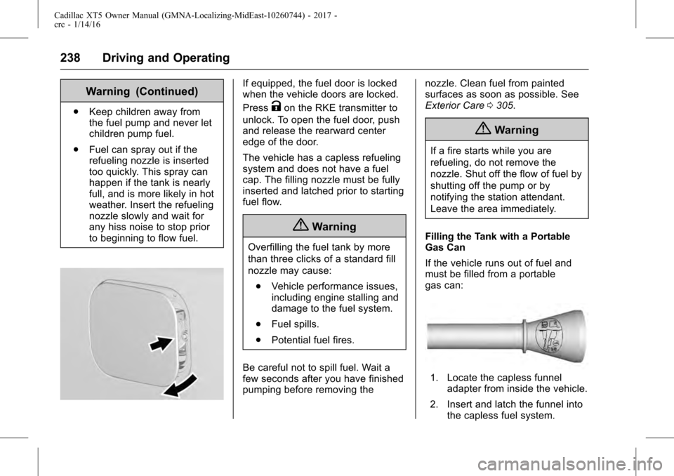
If equipped, the fuel door is locked
when the vehicle doors are locked.
Press
Kon the RKE transmitter to
unlock. To open the fuel door, push
and release the rearward center
edge of the door.
The vehicle has a capless refueling
system and does not have a fuel
cap. The filling nozzle must be fully
inserted and latched prior to starting
fuel flow.
{Warning
Overfilling the fuel tank by more
than three clicks of a standard fill
nozzle may cause:
. Vehicle performance issues,
including engine stalling and
damage to the fuel system.
. Fuel spills.
. Potential fuel fires.
Be careful not to spill fuel. Wait a
few seconds after you have finished
pumping before removing the nozzle. Clean fuel from painted
surfaces as soon as possible. See
Exterior Care
0305.
{Warning
If a fire starts while you are
refueling, do not remove the
nozzle. Shut off the flow of fuel by
shutting off the pump or by
notifying the station attendant.
Leave the area immediately.
Filling the Tank with a Portable
Gas Can
If the vehicle runs out of fuel and
must be filled from a portable
gas can:
1. Locate the capless funnel adapter from inside the vehicle.
2. Insert and latch the funnel into the capless fuel system.
Page 245 of 339
Cadillac XT5 Owner Manual (GMNA-Localizing-MidEast-10260744) - 2017 -
crc - 1/14/16
Driving and Operating 245
After loading the trailer, weigh the
trailer and then the tongue,
separately, to see if the weights are
proper. If they are not, adjustments
might be made by moving some
items around in the trailer.
Trailering may be limited by the
vehicle's ability to carry tongue
weight. Tongue weight cannot cause
the vehicle to exceed the GVWR
(Gross Vehicle Weight Rating) or
the RGAWR (Rear Gross Axle
Weight Rating). The effect of
additional weight may reduce the
trailering capacity more than the
total of the additional weight.
It is important that the vehicle does
not exceed any of its ratings—
GCWR, GVWR, RGAWR, Maximum
Trailer Rating or Tongue Weight.
The only way to be sure it is not
exceeding any of these ratings is to
weigh the vehicle and trailer.
Total Weight on the Vehicle's
Tires
Be sure the vehicle's tires are
inflated to the upper limit for cold
tires. These numbers can be found on the Certification label or see
Vehicle Load Limits
0187. Make
sure not to go over the GVW limit
for the vehicle, or the GAWR,
including the weight of the trailer
tongue. If using a weight distributing
hitch, make sure not to go over the
rear axle limit before applying the
weight distribution spring bars.
Towing Equipment
Hitches
It is important to have the correct
hitch equipment. Crosswinds, large
trucks going by, and rough roads
are a few reasons why the right
hitch is needed.
. The rear bumper on the vehicle
is not intended for hitches. Do
not attach rental hitches or other
bumper-type hitches to it. Use
only a frame-mounted hitch that
does not attach to the bumper.
. Will any holes be made in the
body of the vehicle when the
trailer hitch is installed? If there
are, then be sure to seal the
holes later when the hitch is removed. If the holes are not
sealed, dirt, water, and deadly
carbon monoxide (CO) from the
exhaust can get into the vehicle.
See
Engine Exhaust 0197.
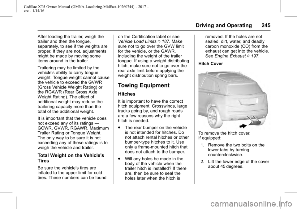
Hitch Cover
To remove the hitch cover,
if equipped: 1. Remove the two bolts on the lower tabs by turning
counterclockwise.
2. Lift the lower edge of the cover about 45 degrees.
Page 246 of 339
Cadillac XT5 Owner Manual (GMNA-Localizing-MidEast-10260744) - 2017 -
crc - 1/14/16
246 Driving and Operating
3. Pull the cover downward todisengage the upper
attachments.
To reinstall the hitch cover: 1. Hold the cover at a 45 degree angle to the vehicle and push
the upper tabs in the hitch
cover into the slots in the
fascia.
2. Move the bottom of the cover forward until the lower tabs line
up with the lower fascia slots.
3. Snap the hitch cover into place by pushing the upper corners
forward.
4. Reinstall the two bolts on the lower tabs by turning
clockwise.
Safety Chains
Always attach chains between the
vehicle and the trailer. Cross the
safety chains under the tongue of
the trailer to help prevent the tongue
from contacting the road if it
becomes separated from the hitch. Always leave just enough slack so
the rig can turn. Never allow safety
chains to drag on the ground.
Trailer Brakes
A loaded trailer that weighs more
than 454 kg (1,000 lb) needs to have
its own brake system that is
adequate for the weight of the
trailer. Be sure to read and follow
the instructions for the trailer brakes
so they are installed, adjusted, and
maintained properly.
Because the vehicle has antilock
brakes, do not tap into the vehicle's
brake system. If you do, both brake
systems will not work well, or at all.
Trailer Wiring Harness
Basic Trailer Wiring
The trailer wiring harness, with a
seven-pin connector, is located at
the rear of the vehicle and is tied to
the vehicle's frame. The harness
connector can be plugged into a
seven-pin universal heavy-duty
trailer connector available through
your dealer.The seven-wire harness contains
the following trailer circuits:
.
Yellow/Gray: Stop/Turn
Signal Left
. Green/Violet: Stop/Turn Signal
Right
. Gray/Brown: Parking Lamps
. White/Green: Back-up Lamps
. Red/Green: Battery Feed
. Black: Ground
. Blue: Electric Brakes*
*The fuse for this circuit is installed
in the underhood electrical center,
but the wires are not connected.
They should be connected by your
dealer or a qualified service center.
If the back-up lamp circuit is not
functional, contact your dealer.
Electric Trailer Brake Control
Wiring Provisions
These wiring provisions for an
electric trailer brake controller are
included with the vehicle as part of
the trailer wiring package. The
instrument panel contains blunt cut
wires above the parking brake
Page 249 of 339
Cadillac XT5 Owner Manual (GMNA-Localizing-MidEast-10260744) - 2017 -
crc - 1/14/16
Vehicle Care 249
Vehicle Care
General Information
General Information . . . . . . . . . . 250
Accessories andModifications . . . . . . . . . . . . . . . . 250
Vehicle Checks
Doing Your OwnService Work . . . . . . . . . . . . . . . 250
Hood . . . . . . . . . . . . . . . . . . . . . . . . . 251
Engine Compartment Overview . . . . . . . . . . . . . . . . . . . . 252
Engine Oil . . . . . . . . . . . . . . . . . . . . 253
Engine Oil Life System . . . . . . . 255
Automatic Transmission Fluid . . . . . . . . . . . . . . . . . . . . . . . . 256
Engine Air Cleaner/Filter . . . . . . 256
Cooling System . . . . . . . . . . . . . . 257
Engine Coolant . . . . . . . . . . . . . . . 258
Engine Overheating . . . . . . . . . . 260
Washer Fluid . . . . . . . . . . . . . . . . . 262
Brakes . . . . . . . . . . . . . . . . . . . . . . . 263
Brake Fluid . . . . . . . . . . . . . . . . . . . 263
Battery . . . . . . . . . . . . . . . . . . . . . . . . 264
All-Wheel Drive . . . . . . . . . . . . . . . 266
Starter Switch Check . . . . . . . . . 266
Park Brake and P (Park) Mechanism Check . . . . . . . . . . 266
Wiper Blade Replacement . . . . 266 Windshield Replacement . . . . . 268
Headlamp Aiming
Headlamp Aiming . . . . . . . . . . . . 268
Bulb Replacement
Bulb Replacement . . . . . . . . . . . . 268
Halogen Bulbs . . . . . . . . . . . . . . . . 268
LED Lighting . . . . . . . . . . . . . . . . . 268
Headlamps . . . . . . . . . . . . . . . . . . . 269
Back-Up Lamps . . . . . . . . . . . . . . 269
License Plate Lamp . . . . . . . . . . 270
Electrical System
Electrical System Overload . . . 271
Fuses and Circuit Breakers . . . 271
Engine Compartment Fuse
Block . . . . . . . . . . . . . . . . . . . . . . . . 272
Instrument Panel Fuse Block . . . . . . . . . . . . . . . . . . . . . . . . 275
Rear Compartment Fuse Block . . . . . . . . . . . . . . . . . . . . . . . . 277
Wheels and Tires
Tires . . . . . . . . . . . . . . . . . . . . . . . . . . 279
All-Season Tires . . . . . . . . . . . . . . 280
Winter Tires . . . . . . . . . . . . . . . . . . 281
Summer Tires . . . . . . . . . . . . . . . . 281
Tire Pressure . . . . . . . . . . . . . . . . . 282
Tire Pressure for High-SpeedOperation . . . . . . . . . . . . . . . . . . . 283 Tire Pressure Monitor
System . . . . . . . . . . . . . . . . . . . . . . 283
Tire Pressure Monitor Operation . . . . . . . . . . . . . . . . . . . 284
Tire Inspection . . . . . . . . . . . . . . . . 287
Tire Rotation . . . . . . . . . . . . . . . . . 288
When It Is Time for New
Tires . . . . . . . . . . . . . . . . . . . . . . . . 289
Buying New Tires . . . . . . . . . . . . . 289
Different Size Tires and Wheels . . . . . . . . . . . . . . . . . . . . . . 291
Wheel Alignment and Tire Balance . . . . . . . . . . . . . . . . . . . . . 291
Wheel Replacement . . . . . . . . . . 291
Tire Chains . . . . . . . . . . . . . . . . . . . 292
If a Tire Goes Flat . . . . . . . . . . . . 293
Tire Changing . . . . . . . . . . . . . . . . 294
Compact Spare Tire . . . . . . . . . . 300
Jump Starting
Jump Starting . . . . . . . . . . . . . . . . 301
Towing the Vehicle
Towing the Vehicle . . . . . . . . . . . 303
Recreational Vehicle Towing . . . . . . . . . . . . . . . . . . . . . . 303
Appearance Care
Exterior Care . . . . . . . . . . . . . . . . . 305
Interior Care . . . . . . . . . . . . . . . . . . 310
Floor Mats . . . . . . . . . . . . . . . . . . . . 313
Page 250 of 339
Cadillac XT5 Owner Manual (GMNA-Localizing-MidEast-10260744) - 2017 -
crc - 1/14/16
250 Vehicle Care
General Information
For service and parts needs, visit
your dealer. You will receive
genuine parts and trained and
supported service people.
Accessories and
Modifications
Adding non-dealer accessories or
making modifications to the vehicle
can affect vehicle performance and
safety, including such things as
airbags, braking, stability, ride and
handling, emissions systems,
aerodynamics, durability, and
electronic systems like antilock
brakes, traction control, and stability
control. These accessories or
modifications could even cause
malfunction or damage not covered
by the vehicle warranty.
Damage to suspension components
caused by modifying vehicle height
outside of factory settings will not be
covered by the warranty.
Damage to vehicle components
resulting from modifications or the
installation or use of non-GMcertified parts, including control
module or software modifications, is
not covered under the terms of the
vehicle warranty and may affect
remaining warranty coverage for
affected parts.
GM Accessories are designed to
complement and function with other
systems on the vehicle. See your
dealer to accessorize the vehicle
using genuine GM Accessories
installed by a dealer technician.
Also, see
Adding Equipment to the
Airbag-Equipped Vehicle 082.
Vehicle Checks
Doing Your Own
Service Work
{Warning
It can be dangerous to work on
your vehicle if you do not have
the proper knowledge, service
manual, tools, or parts. Always
follow owner manual procedures
and consult the service manual
for your vehicle before doing any
service work.
If doing some of your own service
work, use the proper service
manual. It tells you much more
about how to service the vehicle
than this manual can.
This vehicle has an airbag system.
Before attempting to do your own
service work, see Airbag System
Check 082.
Keep a record with all parts receipts
and list the mileage and the date of
any service work performed.
Page 253 of 339
Cadillac XT5 Owner Manual (GMNA-Localizing-MidEast-10260744) - 2017 -
crc - 1/14/16
Vehicle Care 253
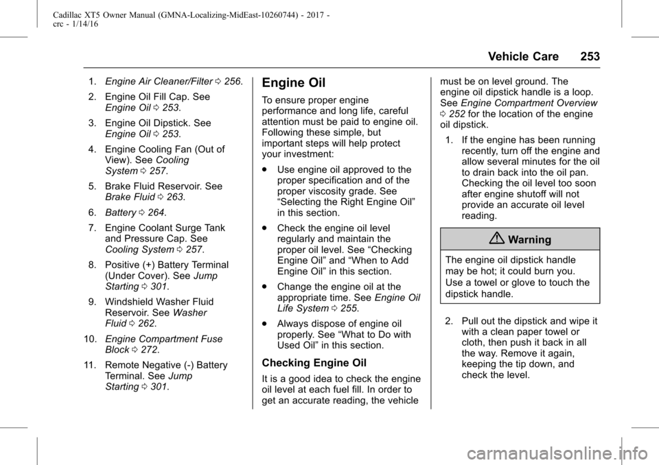
1.Engine Air Cleaner/Filter 0256.
2. Engine Oil Fill Cap. See Engine Oil 0253.
3. Engine Oil Dipstick. See Engine Oil 0253.
4. Engine Cooling Fan (Out of View). See Cooling
System 0257.
5. Brake Fluid Reservoir. See Brake Fluid 0263.
6. Battery 0264.
7. Engine Coolant Surge Tank and Pressure Cap. See
Cooling System 0257.
8. Positive (+) Battery Terminal (Under Cover). See Jump
Starting 0301.
9. Windshield Washer Fluid Reservoir. See Washer
Fluid 0262.
10. Engine Compartment Fuse
Block 0272.
11. Remote Negative (-) Battery Terminal. See Jump
Starting 0301.Engine Oil
To ensure proper engine
performance and long life, careful
attention must be paid to engine oil.
Following these simple, but
important steps will help protect
your investment:
.
Use engine oil approved to the
proper specification and of the
proper viscosity grade. See
“Selecting the Right Engine Oil”
in this section.
. Check the engine oil level
regularly and maintain the
proper oil level. See “Checking
Engine Oil” and“When to Add
Engine Oil” in this section.
. Change the engine oil at the
appropriate time. See Engine Oil
Life System 0255.
. Always dispose of engine oil
properly. See “What to Do with
Used Oil” in this section.
Checking Engine Oil
It is a good idea to check the engine
oil level at each fuel fill. In order to
get an accurate reading, the vehicle must be on level ground. The
engine oil dipstick handle is a loop.
See
Engine Compartment Overview
0 252 for the location of the engine
oil dipstick.
1. If the engine has been running recently, turn off the engine and
allow several minutes for the oil
to drain back into the oil pan.
Checking the oil level too soon
after engine shutoff will not
provide an accurate oil level
reading.
{Warning
The engine oil dipstick handle
may be hot; it could burn you.
Use a towel or glove to touch the
dipstick handle.
2. Pull out the dipstick and wipe it with a clean paper towel or
cloth, then push it back in all
the way. Remove it again,
keeping the tip down, and
check the level.
Page 260 of 339
Cadillac XT5 Owner Manual (GMNA-Localizing-MidEast-10260744) - 2017 -
crc - 1/14/16
260 Vehicle Care
Caution
This vehicle has a specific
coolant fill procedure. Failure to
follow this procedure could cause
the engine to overheat and be
severely damaged.
{Warning
Steam and scalding liquids from a
hot cooling system can blow out
and burn you badly. Never turn
the cap when the cooling system,
including the surge tank pressure
cap, is hot. Wait for the cooling
system and surge tank pressure
cap to cool.
The coolant surge tank pressure
cap can be removed when the
cooling system, including the surge
tank pressure cap and upper
radiator hose, is no longer hot.1. Turn the pressure cap slowly counterclockwise. If a hiss is
heard, wait for that to stop.
A hiss means there is still
some pressure left.
2. Keep turning the pressure cap slowly and remove it.
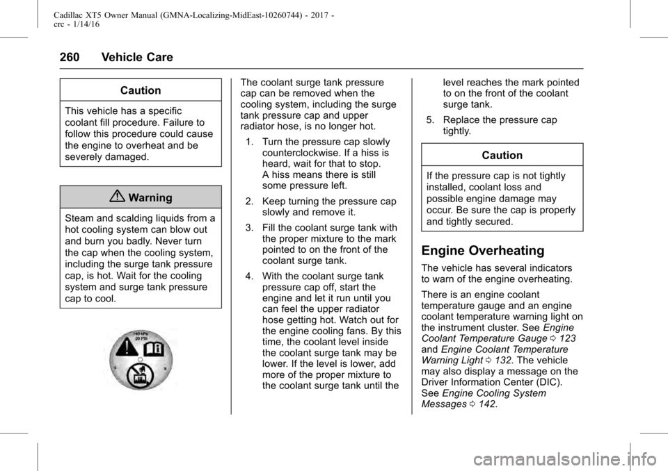
3. Fill the coolant surge tank with the proper mixture to the mark
pointed to on the front of the
coolant surge tank.
4. With the coolant surge tank pressure cap off, start the
engine and let it run until you
can feel the upper radiator
hose getting hot. Watch out for
the engine cooling fans. By this
time, the coolant level inside
the coolant surge tank may be
lower. If the level is lower, add
more of the proper mixture to
the coolant surge tank until the level reaches the mark pointed
to on the front of the coolant
surge tank.
5. Replace the pressure cap tightly.
Caution
If the pressure cap is not tightly
installed, coolant loss and
possible engine damage may
occur. Be sure the cap is properly
and tightly secured.
Engine Overheating
The vehicle has several indicators
to warn of the engine overheating.
There is an engine coolant
temperature gauge and an engine
coolant temperature warning light on
the instrument cluster. See Engine
Coolant Temperature Gauge 0123
and Engine Coolant Temperature
Warning Light 0132. The vehicle
may also display a message on the
Driver Information Center (DIC).
See Engine Cooling System
Messages 0142.
Page 269 of 339
Cadillac XT5 Owner Manual (GMNA-Localizing-MidEast-10260744) - 2017 -
crc - 1/14/16
Vehicle Care 269
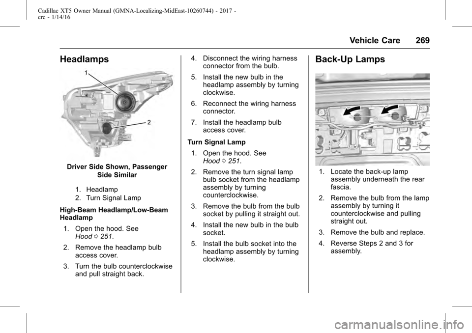
Headlamps
Driver Side Shown, PassengerSide Similar
1. Headlamp
2. Turn Signal Lamp
High-Beam Headlamp/Low-Beam
Headlamp
1. Open the hood. See Hood 0251.
2. Remove the headlamp bulb access cover.
3. Turn the bulb counterclockwise and pull straight back. 4. Disconnect the wiring harness
connector from the bulb.
5. Install the new bulb in the headlamp assembly by turning
clockwise.
6. Reconnect the wiring harness connector.
7. Install the headlamp bulb access cover.
Turn Signal Lamp 1. Open the hood. See Hood 0251.
2. Remove the turn signal lamp bulb socket from the headlamp
assembly by turning
counterclockwise.
3. Remove the bulb from the bulb socket by pulling it straight out.
4. Install the new bulb in the bulb socket.
5. Install the bulb socket into the headlamp assembly by turning
clockwise.
Back-Up Lamps
1. Locate the back-up lampassembly underneath the rear
fascia.
2. Remove the bulb from the lamp assembly by turning it
counterclockwise and pulling
straight out.
3. Remove the bulb and replace.
4. Reverse Steps 2 and 3 for assembly.
Page 270 of 339
Cadillac XT5 Owner Manual (GMNA-Localizing-MidEast-10260744) - 2017 -
crc - 1/14/16
270 Vehicle Care
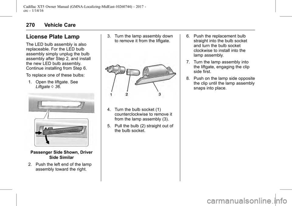
License Plate Lamp
The LED bulb assembly is also
replaceable. For the LED bulb
assembly simply unplug the bulb
assembly after Step 2, and install
the new LED bulb assembly.
Continue installing from Step 6.
To replace one of these bulbs:1. Open the liftgate. See Liftgate 036.
Passenger Side Shown, Driver
Side Similar
2. Push the left end of the lamp assembly toward the right. 3. Turn the lamp assembly down
to remove it from the liftgate.
4. Turn the bulb socket (1)counterclockwise to remove it
from the lamp assembly (3).
5. Pull the bulb (2) straight out of the bulb socket. 6. Push the replacement bulb
straight into the bulb socket
and turn the bulb socket
clockwise to install into the
lamp assembly.
7. Turn the lamp assembly into the liftgate, engaging the clip
side first.
8. Push on the lamp side opposite the clip until the lamp assembly
snaps into place.