instrument cluster CADILLAC XT5 2020 Owner's Guide
[x] Cancel search | Manufacturer: CADILLAC, Model Year: 2020, Model line: XT5, Model: CADILLAC XT5 2020Pages: 384, PDF Size: 6.52 MB
Page 206 of 384
DRIVING AND OPERATING 205
Warning (Continued)
vehicle at a stop, always be
prepared to manually apply the
brakes.
{Warning
Leaving the vehicle without placing
it in P (Park) can be dangerous. Do
not leave the vehicle while it is
being held at a stop by ACC. Always
place the vehicle in P (Park) and
turn off the ignition before leaving
the vehicle.
ACC Override
If using the accelerator pedal while
ACC is active, the ACC indicator turns
blue on the instrument cluster and in
the HUD (if equipped) to indicate that
automatic braking will not occur. ACC
will resume operation when the
accelerator pedal is not being pressed.
{Warning
The ACC will not automatically
apply the brakes if your foot is
resting on the accelerator pedal.
You could crash into a vehicle
ahead of you.
Curves in the Road
{Warning
On curves, ACC may not detect a
vehicle ahead in your lane. You
could be startled if the vehicle
accelerates up to the set speed,
especially when following a vehicle
exiting or entering exit ramps. You
could lose control of the vehicle or
crash. Do not use ACC while driving
on an entrance or exit ramp. Always
be ready to use the brakes if
necessary.
{Warning
On curves, ACC may respond to a
vehicle in another lane, or may not
have time to react to a vehicle in
your lane. You could crash into a
vehicle ahead of you, or lose control
of your vehicle. Give extra attention
in curves and be ready to use the
brakes if necessary. Select an
appropriate speed while driving in
curves.
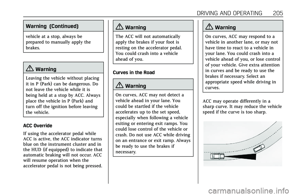
ACC may operate differently in a
sharp curve. It may reduce the vehicle
speed if the curve is too sharp.
Page 213 of 384
212 DRIVING AND OPERATING
Warning (Continued)
(8 mph), to briefly check the status
of your trailer. Do not use for any
other purpose, such as making lane
change decisions. Before making a
lane change, always check the
mirrors and glance over your
shoulder. Improper use could result
in serious injury to you or others.
Park Assist
With Front and Rear Park Assist, as
the vehicle moves at speeds of less
than 8 km/h (5 mph) the sensors on
the bumpers may detect objects up to
1.2 m (4 ft) in front and 2.5 m (8 ft)
behind the vehicle within a zone
25 cm (10 in) high off the ground and
below bumper level. These detection
distances may be shorter during
warmer or humid weather. Blocked
sensors will not detect objects and
can also cause false detections. Keep
the sensors clean of mud, dirt, snow,
ice, and slush; and clean sensors after
a car wash in freezing temperatures.
{Warning
The Park Assist system does not
detect children, pedestrians,
bicyclists, animals, or objects
located below the bumper or that
are too close or too far from the
vehicle. It is not available at speeds
greater than 8 km/h (5 mph). To
prevent injury, death, or vehicle
damage, even with Park Assist,
always check the area around the
vehicle and check all mirrors before
moving forward or backing.
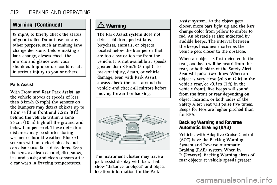
The instrument cluster may have a
park assist display with bars that
show “distance to object ”and object
location information for the Park Assist system. As the object gets
closer, more bars light up and the bars
change color from yellow to amber to
red. An obstacle is also indicated by
audible beeps. The interval between
the beeps becomes shorter as the
vehicle gets closer to the obstacle.
When an object is first detected in the
rear, one beep will be heard from the
rear, or both sides of the Safety Alert
Seat will pulse two times. When an
object is very close (<0.6 m (2 ft) in the
vehicle rear, or <0.3 m (1 ft) in the
vehicle front), five beeps will sound
from the front or rear depending on
object location, or both sides of the
Safety Alert Seat will pulse five times.
Beeps for FPA are higher pitched than
for RPA.
Backing Warning and Reverse
Automatic Braking (RAB)
Vehicles with Adaptive Cruise Control
(ACC) have the Backing Warning
System and Reverse Automatic
Braking (RAB) system. When in
R (Reverse), Backing Warning alerts of
rear objects at vehicle speeds greater
Page 225 of 384

224 DRIVING AND OPERATING
With the Front Pedestrian Braking
system turned on, Night Vision
provides a red Head-Up Display (HUD)
alert when the system detects that the
vehicle is approaching a pedestrian
ahead too quickly. In addition, an alert
beeps or the Safety Alert Seat pulses,
if equipped. SeeFront Pedestrian
Braking (FPB) System 0221.
{Warning
The system does not detect all
objects or the vehicle distance from
objects. The system may not
provide a warning with enough time
to help avoid a crash.
1. Low-Beam Headlamps
2. High-Beam Headlamps
3. Night Vision System
By selecting a view on the instrument
cluster, the Night Vision image can be
displayed. See Instrument Cluster 0108
. The Night Vision system can operate
only if:
. The ignition is on.
. The vehicle is in P (Park) or a
forward gear.
. It is dark enough outside.
. The headlamps are on, except
when parked. Adjust the instrument panel
brightness to make the image no
brighter than necessary. Turn the
image off by selecting another view
on the instrument cluster.
Warm objects, such as pedestrians,
animals, and other moving vehicles,
should appear whiter on the Night
Vision display. Cold objects, such as
the sky, signs, and parked vehicles,
should appear darker. Night Vision
only shows objects that are warmer or
colder than the surroundings. It does
not detect brake lamps, turn signals,
emergency flashers, traffic lights,
or sign information.
Use this system as an aid by
occasionally glancing at the image. Do
not stare at the image or use the
image under well-lit conditions.
{Warning
Do not stare at the image while
driving as this might cause
important objects ahead not to be
seen. You could crash, and you or
others could be injured.
Page 226 of 384

DRIVING AND OPERATING 225
When a pedestrian or large animal is
detected, an amber box displays
around the pedestrian or animal on
the Night Vision display and an amber
pedestrian icon,
~, or animal icon,
!, displays on the instrument
cluster. This pedestrian icon is also
shown on the Head-Up Display (HUD).
When the system detects the vehicle
is approaching a pedestrian too
quickly, the amber pedestrian icon
and box turns red, and a red flashing
icon,
~, displays on the HUD with
rapid beeping or pulsing of the Safety
Alert Seat, if equipped.
System pedestrian icons, beeps, and
(if equipped) Safety Alert Seat pulses
can be set to Off through vehicle
personalization by turning off the
Front Pedestrian Braking system. See
“Front Pedestrian Detection ”in
“Collision/Detection Systems” under
Vehicle Personalization 0131.
{Warning
The Night Vision system does not
automatically brake the vehicle.
It does not provide alerts unless it
detects a pedestrian or large
animal. The system may not detect
pedestrians, including children,
or animals:
. If they are less than 25 m
(82 ft) away.
. If they are not directly ahead
in the sensor coverage area,
fully visible, standing upright,
or part of a group.
. If the person or animal is
moving too quickly through
the field of view, such as a
bicyclist.
. If the pedestrian is wearing
certain types of clothing.
. If headlamps are off, except
when parked.
. If the outside temperature is
higher than 30 °C (86 °F).
(Continued)
Warning (Continued)
.Due to poor visibility,
including in heavy fog, rain,
or snow.
. If the sensor is blocked by
dirt, snow, rain, or ice.
Be ready to take action and apply
the brakes. For more information,
see Defensive Driving 0160. Keep
the Night Vision sensor clean and
in good repair.
Pedestrian detection may not be
available in high outside temperatures.
An amber icon,
*, displays. The
system does not need service.
In rain, snow, or fog the image may
not be clear and the direction of the
road ahead may not be seen. In more
severe weather conditions, the image
may be unclear and unusable. The
system does not need service.
Keep the system sensor clean by
activating the rear window washer
when it is dark enough for the system
to operate. If the Night Vision image
Page 245 of 384
244 DRIVING AND OPERATING
Tail/Parking
LampsGray/Brown
Reverse Lamps White/Green
Battery Feed Red/Green
Ground Black
Electric Trailer
Brake* Blue
* Circuit powered by electric trailer
brake control wiring provisions.
Electric Trailer Brake Control
Wiring Provisions
Wiring provisions for an aftermarket
electric trailer brake controller are
included with the vehicle as part of
the trailer wiring package. The
harness contains the following
circuits: Electric Trailer
Brakes Blue
Battery Feed Red/Green or
Red/Blue
Brake Apply
Signal White/Blue
Ground Black Refer to the aftermarket electric trailer
brake controller owner's manual to
determine wire color coding of the
electric trailer brake controller. The
wire colors on the brake controller
may be different from the vehicle. The
electric trailer brake controller should
be installed by your dealer or a
qualified service center.
If equipped, there are four blunt cut
wires inside the front driver side
instrument panel. It will be necessary
to have a technician connect the
12-volt power to the engine
compartment fuse block.Trailer Lamps
Always check all trailer lamps are
working at the beginning of each trip,
and periodically on longer trips.
Turn Signals When Towing a
Trailer
When properly connected, the trailer
turn signals will illuminate to indicate
the vehicle is turning, changing lanes,
or stopping. When towing a trailer,
the arrows on the instrument cluster
will illuminate even if the trailer is not
properly connected or the bulbs are
burned out.
Always check all trailer lamps are
working at the beginning of each trip,
and periodically on longer trips.
Trailer Sway Control (TSC)
Vehicles with StabiliTrak/Electronic
Stability Control (ESC) have a Trailer
Sway Control (TSC) feature. Trailer
sway is unintended side-to-side
motion of a trailer while towing. If the
vehicle is towing a trailer and the TSC
detects that sway is increasing, the
vehicle brakes are selectively applied
at each wheel, to help reduce
excessive trailer sway. If equipped with
the Integrated Trailer Brake Control
(ITBC) system, and the trailer has an
electric brake system, StabiliTrak/ESC
may also apply the trailer brakes.
Page 246 of 384
DRIVING AND OPERATING 245
If TSC is enabled, the Traction Control
System (TCS)/StabiliTrak/ESC warning
light will flash on the instrument
cluster. Reduce vehicle speed by
gradually removing your foot from the
accelerator. If trailer sway continues,
StabiliTrak/ESC can reduce engine
torque to help slow the vehicle. TSC
will not function if StabiliTrak/ESC is
turned off. SeeTraction Control/
Electronic Stability Control 0193.
{Warning
Trailer sway can result in a crash
and in serious injury or death, even
if the vehicle is equipped with TSC.
If the trailer begins to sway, reduce
vehicle speed by gradually removing
your foot from the accelerator. Then
pull over to check the trailer and
vehicle to help correct possible
causes, including an improperly or
overloaded trailer, unrestrained
cargo, improper trailer hitch
configuration, or improperly
inflated or incorrect vehicle or
(Continued)
Warning (Continued)
trailer tires. SeeTowing Equipment
0 241 for trailer ratings and hitch
setup recommendations.
Trailer Tires
Special Trailer (ST) tires differ from
vehicle tires. Trailer tires are designed
with stiff sidewalls to help prevent
sway and to support heavy loads.
These features can make it difficult to
determine if the trailer tire pressures
are low only based on a visual
inspection.
Always check all trailer tire pressures
before each trip when the tires are
cool. Low trailer tire pressure is a
leading cause of trailer tire blow-outs.
Trailer tires deteriorate over time. The
trailer tire sidewall will show the week
and year the tire was manufactured.
Many trailer tire manufacturers
recommend replacing tires more than
six years old. Overloading is another leading cause
of trailer tire blow-outs. Never load
your trailer with more weight than the
tires are designed to support. The load
rating is located on the trailer tire
sidewall.
Always know the maximum speed
rating for the trailer tires before
driving. This may be significantly
lower than the vehicle tire speed
rating. The speed rating may be on
the trailer tire sidewall. If the speed
rating is not shown, the default trailer
tire speed rating is 105 km/h
(65 mph).
Page 277 of 384

276 VEHICLE CARE
FusesUsage
F5 DC DC transformer 2
F6 Amplifier 1
F7 Front blower
F8 Starter 3
F9 –
F10 –
F11 –
F12 Front wiper
F13 Starter 2
F14 LED/Automatic headlamp leveling
F15 Rear wiper 1
F16 –
F17 –
F18 Automatic headlamp leveling module
F19 –
F20 –
F21 –
F22 Electronic brake control module Fuses
Usage
F23 Parking/Trailer lamps
F24 Right trailer stoplamp/Turnlamp
F25 Steering column lock
F26 –
F27 Left trailer stoplamp/ Turnlamp
F28 –
F29 –
F30 Washer pump
F31 –
F32 –
F33 Fog lamps
F34 Horn
F35 –
F36 Headlamp high-beam –left
F37 Headlamp high-beam –right
F38 Automatic headlamp leveling motor Fuses
Usage
F39 Transmission control module/Battery 1
F40 Left rear bus electrical center/Ignition
F41 Instrument cluster
F42 Heating, ventilation, and air conditioning
F43 Head-Up display
F44 Electronic brake control module
electric brake booster/
Run/Crank
F45 –
F46 –
F47 –
F48 Rear wiper 2
F49 Interior rearview mirror/Trailer
F50 Fuel system control module
F51 Heated steering wheel
F52 Air conditioning clutch
Page 280 of 384
VEHICLE CARE 279
FusesUsage
F16 Sunroof
F17 Body control module 1
F18 Instrument cluster
F19 –
F20 Rear seat entertainment
F21 Body control module 4
F22 Infotainment/USB data/Aux jack
F23 Body control module 2
F24 USB charger/ Wireless charging
F25 Park aid/electronic transmission range
system
F26 Communications integration module
F27 Video Fuses
Usage
F28 Heating, ventilation, and air conditioning
display
F29 Radio
F30 Steering wheel adjustment controls
F31 Electronic brake control module
electric brake
booster
F32 DC AC inverter
F33 Driver power seat
F34 Passenger power seat
F35 Battery IEC 1 feed
F36 Electric power steering
F37 Rear seat entertainment/USB
charge/Wireless
charging module
F38 Body control module 8
F39 – Circuit
Breakers Usage
F40 –
F41 –
F42 Auxiliary power outlet/Lighter
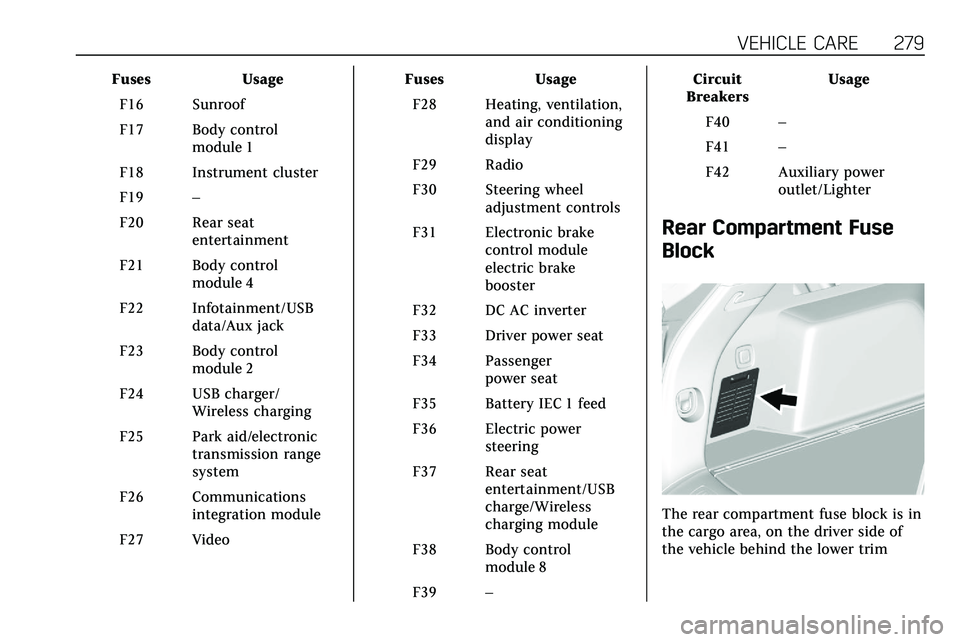
Rear Compartment Fuse
Block
The rear compartment fuse block is in
the cargo area, on the driver side of
the vehicle behind the lower trim
Page 293 of 384
292 VEHICLE CARE
Tire Pressure Monitor
Operation
This vehicle may have a Tire Pressure
Monitor System (TPMS). The TPMS is
designed to warn the driver when a
low tire pressure condition exists.
TPMS sensors are mounted onto each
tire and wheel assembly, excluding the
spare tire and wheel assembly. The
TPMS sensors monitor the air
pressure in the tires and transmit the
tire pressure readings to a receiver
located in the vehicle.
When a low tire pressure condition is
detected, the TPMS illuminates the
low tire pressure warning light on the
instrument cluster. If the warning
light comes on, stop as soon as
possible and inflate the tires to the
recommended pressure shown on the
Tire and Loading Information label.
SeeVehicle Load Limits 0170. A message to check the pressure in a
specific tire displays in the Driver
Information Center (DIC). The low tire
pressure warning light and the DIC
warning message come on at each
ignition cycle until the tires are
inflated to the correct inflation
pressure. Using the DIC, tire pressure
levels can be viewed. For additional
information and details about the DIC
operation and displays see
Driver
Information Center (DIC) 0124.
The low tire pressure warning light
may come on in cool weather when
the vehicle is first started, and then
turn off as the vehicle is driven. This
could be an early indicator that the air
pressure is getting low and needs to
be inflated to the proper pressure.
A Tire and Loading Information label,
attached to your vehicle, shows the
size of the original equipment tires
and the correct inflation pressure for
the tires when they are cold. See
Vehicle Load Limits 0170, for an
example of the Tire and Loading
Information label and its location.
Also see Tire Pressure 0289. The TPMS can warn about a low tire
pressure condition but it does not
replace normal tire maintenance. See
Tire Inspection
0295, Tire Rotation
0 296 and
Tires 0282.
Caution
Tire sealant materials are not all
the same. A non-approved tire
sealant could damage the TPMS
sensors. TPMS sensor damage
caused by using an incorrect tire
sealant is not covered by the
vehicle warranty. Always use only
the GM approved tire sealant
available through your dealer or
included in the vehicle.
Factory-installed Tire Inflator Kits use
a GM approved liquid tire sealant.
Using non-approved tire sealants
could damage the TPMS sensors. See
Tire Sealant and Compressor Kit 0304
for information regarding the inflator
kit materials and instructions.
Page 328 of 384

VEHICLE CARE 327
the fluid. Contaminated fluid will
decrease the life of the transfer case
and/or axles and should be replaced.
Sheet Metal Damage
If the vehicle is damaged and requires
sheet metal repair or replacement,
make sure the body repair shop
applies anti-corrosion material to
parts repaired or replaced to restore
corrosion protection.
Original manufacturer replacement
parts will provide the corrosion
protection while maintaining the
vehicle warranty.
Finish Damage
Quickly repair minor chips and
scratches with touch-up materials
available from your dealer to avoid
corrosion. Larger areas of finish
damage can be corrected in your
dealer's body and paint shop.
Chemical Paint Spotting
Airborne pollutants can fall upon and
attack painted vehicle surfaces
causing blotchy, ring-shaped
discolorations, and small, irregulardark spots etched into the paint
surface. See
“Finish Care”previously in
this section.
Interior Care
To prevent dirt particle abrasions,
regularly clean the vehicle's interior.
Immediately remove any soils.
Newspapers or dark garments can
transfer color to the vehicle’s interior.
Use a soft bristle brush to remove
dust from knobs and crevices on the
instrument cluster. Using a mild soap
solution, immediately remove hand
lotions, sunscreen, and insect
repellent from all interior surfaces or
permanent damage may result.
Use cleaners specifically designed for
the surfaces being cleaned to prevent
permanent damage. Apply all cleaners
directly to the cleaning cloth. Do not
spray cleaners on any switches or
controls. Remove cleaners quickly.
Before using cleaners, read and follow
all safety instructions on the label.
While cleaning the interior, open the
doors and windows to get proper
ventilation. To prevent damage, do not clean the
interior using the following cleaners
or techniques:
.
Never use a razor or any other
sharp object to remove soil from
any interior surface.
. Never use a brush with stiff
bristles.
. Never rub any surface aggressively
or with too much pressure.
. Do not use laundry detergents or
dishwashing soaps with
degreasers. For liquid cleaners, use
approximately 20 drops per 3.8 L
(1 gal) of water. A concentrated
soap solution will create streaks
and attract dirt. Do not use
solutions that contain strong or
caustic soap.
. Do not heavily saturate the
upholstery when cleaning.
. Do not use solvents or cleaners
containing solvents.