stop start CADILLAC XT5 2020 Service Manual
[x] Cancel search | Manufacturer: CADILLAC, Model Year: 2020, Model line: XT5, Model: CADILLAC XT5 2020Pages: 384, PDF Size: 6.52 MB
Page 264 of 384

VEHICLE CARE 263
How to Add Coolant to the
Surge Tank
{Warning
Spilling coolant on hot engine parts
can burn you. Coolant contains
ethylene glycol and it will burn if
the engine parts are hot enough.
{Warning
Steam and scalding liquids from a
hot cooling system are under
pressure. Turning the pressure cap,
even a little, can cause them to
come out at high speed and you
could be burned. Never turn the cap
when the cooling system, including
the pressure cap, is hot. Wait for
the cooling system and pressure
cap to cool.
Caution
Failure to follow the specific
coolant fill procedure could cause
the engine to overheat and could
cause system damage. If coolant is
not visible in the surge tank,
contact your dealer.
The coolant surge tank pressure cap
can be removed when the cooling
system, including the surge tank
pressure cap and upper radiator hose,
is no longer hot.
Coolant Fill Instructions (3.6L
Engine Only)
1. Turn the pressure cap slowly counterclockwise. If a hiss is
heard, wait for that to stop.
A hiss means there is still some
pressure left. 2. Keep turning the pressure cap
slowly and remove it.
3. Fill the coolant surge tank withthe proper mixture to the mark
pointed to on the front of the
coolant surge tank.
4. With the coolant surge tank pressure cap off, start the engine
and let it run until you can feel
the upper radiator hose getting
hot. Watch out for the engine
cooling fans. By this time, the
coolant level inside the coolant
surge tank may be lower. If the
level is lower, add more of the
proper mixture to the coolant
Page 269 of 384
268 VEHICLE CARE
new brake linings are installed. Add or
remove fluid, as necessary, only when
work is done on the brake hydraulic
system.
{Warning
If too much brake fluid is added, it
can spill on the engine and burn,
if the engine is hot enough. You or
others could be burned, and the
vehicle could be damaged. Add
brake fluid only when work is done
on the brake hydraulic system.
When the brake fluid falls to a low
level, the brake warning light comes
on. See Brake System Warning Light
0 117.
Brake fluid absorbs water over time
which degrades the effectiveness of
the brake fluid. Replace brake fluid at
the specified intervals to prevent
increased stopping distance. See
Maintenance Schedule 0332. What to Add
Use only GM approved DOT 3 brake
fluid from a clean, sealed container.
See
Recommended Fluids and
Lubricants 0342.{Warning
The wrong or contaminated brake
fluid could result in damage to the
brake system. This could result in
the loss of braking leading to a
possible injury. Always use the
proper GM approved brake fluid.
Caution
If brake fluid is spilled on the
vehicle's painted surfaces, the paint
finish can be damaged. Immediately
wash off any painted surface.
Battery - North America
The original equipment battery is
maintenance free. Do not remove the
cap and do not add fluid. Refer to the replacement number on
the original battery label when a new
battery is needed. For replacement of
the battery, see your dealer.
The vehicle has an Absorbed Glass
Mat (AGM) 12-volt battery.
Installation of a standard 12-volt
battery will result in reduced 12-volt
battery life.
When using a 12-volt battery charger
on the 12-volt AGM battery, some
chargers have an AGM battery setting
on the charger. If available, use the
AGM setting on the charger, to limit
charge voltage to 14.8 volts.
Stop/Start System
This vehicle has a Stop/Start system
to shut off the engine to help
conserve fuel. See
Stop/Start System
0 177.
{Warning
WARNING: Battery posts,
terminals, and related accessories
contain lead and lead compounds,
(Continued)
Page 272 of 384
VEHICLE CARE 271
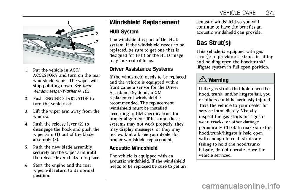
1. Put the vehicle in ACC/ACCESSORY and turn on the rear
windshield wiper. The wiper will
stop pointing down. See Rear
Window Wiper/Washer 0103.
2. Push ENGINE START/STOP to turn the vehicle off.
3. Lift the wiper arm away from the window.
4. Push the release lever (2) to disengage the hook and push the
wiper arm (1) out of the blade
assembly (3).
5. Push the new blade assembly securely on the wiper arm until
the release lever clicks into place.
6. Start the engine and the rear wiper will return to its normal
position.
Windshield Replacement
HUD System
The windshield is part of the HUD
system. If the windshield needs to be
replaced, be sure to get one that is
designed for HUD or the HUD image
may look out of focus.
Driver Assistance Systems
If the windshield needs to be replaced
and the vehicle is equipped with a
front camera sensor for the Driver
Assistance Systems, a GM
replacement windshield is
recommended. The replacement
windshield must be installed
according to GM specifications for
proper alignment. If it is not, these
systems may not work properly, they
may display messages, or they may
not work at all. See your dealer for
proper windshield replacement.
Acoustic Windshield
The vehicle is equipped with an
acoustic windshield. If the windshield
needs to be replaced be sure to get an acoustic windshield so you will
continue to have the benefits an
acoustic windshield can provide.
Gas Strut(s)
This vehicle is equipped with gas
strut(s) to provide assistance in lifting
and holding open the hood/trunk/
liftgate system in full open position.
{Warning
If the gas struts that hold open the
hood, trunk, and/or liftgate fail, you
or others could be seriously injured.
Take the vehicle to your dealer for
service immediately. Visually
inspect the gas struts for signs of
wear, cracks, or other damage
periodically. Check to make sure the
hood/trunk/liftgate is held open
with enough force. If struts are
failing to hold the hood/trunk/
liftgate, do not operate. Have the
vehicle serviced.
Page 275 of 384
274 VEHICLE CARE
Headlamp Wiring
An electrical overload may cause the
lamps to go on and off, or in some
cases to remain off. Have the
headlamp wiring checked right away if
the lamps go on and off or remain off.
Windshield Wipers
If the wiper motor overheats due to
heavy snow or ice, the windshield
wipers will stop until the motor cools
and will then restart.
Although the circuit is protected from
electrical overload, overload due to
heavy snow or ice may cause wiper
linkage damage. Always clear ice and
heavy snow from the windshield
before using the windshield wipers.
If the overload is caused by an
electrical problem and not snow or
ice, be sure to get it fixed.
Fuses and Circuit Breakers
The wiring circuits in the vehicle are
protected from short circuits by a
combination of fuses and circuitbreakers. This greatly reduces the
chance of damage caused by electrical
problems.
{Danger
Fuses and circuit breakers are
marked with their ampere rating.
Do not exceed the
specified amperage rating when
replacing fuses and circuit breakers.
Use of an oversized fuse or circuit
breaker can result in a vehicle fire.
You and others could be seriously
injured or killed.
To check a fuse, look at the
silver-colored band inside the fuse.
If the band is broken or melted,
replace the fuse. Be sure to replace a
bad fuse with a new one of the
identical size and rating.
Fuses of the same amperage can be
temporarily borrowed from another
fuse location, if a fuse goes out.
Replace the fuse as soon as possible.
Engine Compartment Fuse
Block
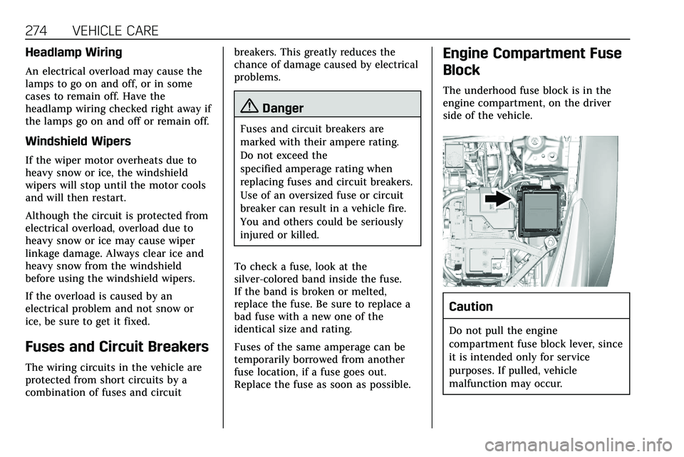
The underhood fuse block is in the
engine compartment, on the driver
side of the vehicle.
Caution
Do not pull the engine
compartment fuse block lever, since
it is intended only for service
purposes. If pulled, vehicle
malfunction may occur.
Page 277 of 384

276 VEHICLE CARE
FusesUsage
F5 DC DC transformer 2
F6 Amplifier 1
F7 Front blower
F8 Starter 3
F9 –
F10 –
F11 –
F12 Front wiper
F13 Starter 2
F14 LED/Automatic headlamp leveling
F15 Rear wiper 1
F16 –
F17 –
F18 Automatic headlamp leveling module
F19 –
F20 –
F21 –
F22 Electronic brake control module Fuses
Usage
F23 Parking/Trailer lamps
F24 Right trailer stoplamp/Turnlamp
F25 Steering column lock
F26 –
F27 Left trailer stoplamp/ Turnlamp
F28 –
F29 –
F30 Washer pump
F31 –
F32 –
F33 Fog lamps
F34 Horn
F35 –
F36 Headlamp high-beam –left
F37 Headlamp high-beam –right
F38 Automatic headlamp leveling motor Fuses
Usage
F39 Transmission control module/Battery 1
F40 Left rear bus electrical center/Ignition
F41 Instrument cluster
F42 Heating, ventilation, and air conditioning
F43 Head-Up display
F44 Electronic brake control module
electric brake booster/
Run/Crank
F45 –
F46 –
F47 –
F48 Rear wiper 2
F49 Interior rearview mirror/Trailer
F50 Fuel system control module
F51 Heated steering wheel
F52 Air conditioning clutch
Page 292 of 384
VEHICLE CARE 291
flange. It will read something like this:
Maximum load 690 kg (1,521 lbs)
300 kPa (44 psi) Max. Press.
Tire Pressure Monitor
System
The Tire Pressure Monitor System
(TPMS) uses radio and sensor
technology to check tire pressure
levels. The TPMS sensors monitor the
air pressure in your tires and transmit
tire pressure readings to a receiver
located in the vehicle.
Each tire, including the spare (if
provided), should be checked monthly
when cold and inflated to the
inflation pressure recommended by
the vehicle manufacturer on the
vehicle placard or tire inflation
pressure label. (If your vehicle has
tires of a different size than the size
indicated on the vehicle placard or tire
inflation pressure label, you should
determine the proper tire inflation
pressure for those tires.)
As an added safety feature, your
vehicle has been equipped with a tire
pressure monitoring system (TPMS)that illuminates a low tire pressure
telltale when one or more of your tires
is significantly under-inflated.
Accordingly, when the low tire
pressure telltale illuminates, you
should stop and check your tires as
soon as possible, and inflate them to
the proper pressure. Driving on a
significantly under-inflated tire causes
the tire to overheat and can lead to
tire failure. Under-inflation also
reduces fuel efficiency and tire tread
life, and may affect the vehicle's
handling and stopping ability.
Please note that the TPMS is not a
substitute for proper tire maintenance,
and it is the driver's responsibility to
maintain correct tire pressure, even if
under-inflation has not reached the
level to trigger illumination of the
TPMS low tire pressure telltale.
Your vehicle has also been equipped
with a TPMS malfunction indicator to
indicate when the system is not
operating properly. The TPMS
malfunction indicator is combined
with the low tire pressure telltale.
When the system detects a
malfunction, the telltale will flash forapproximately one minute and then
remain continuously illuminated. This
sequence will continue upon
subsequent vehicle start-ups as long
as the malfunction exists.
When the malfunction indicator is
illuminated, the system may not be
able to detect or signal low tire
pressure as intended. TPMS
malfunctions may occur for a variety
of reasons, including the installation
of replacement or alternate tires or
wheels on the vehicle that prevent the
TPMS from functioning properly.
Always check the TPMS malfunction
telltale after replacing one or more
tires or wheels on your vehicle to
ensure that the replacement or
alternate tires and wheels allow the
TPMS to continue to function
properly.
See
Tire Pressure Monitor Operation
0 292.
See Radio Frequency Statement 0358.
Page 293 of 384
292 VEHICLE CARE
Tire Pressure Monitor
Operation
This vehicle may have a Tire Pressure
Monitor System (TPMS). The TPMS is
designed to warn the driver when a
low tire pressure condition exists.
TPMS sensors are mounted onto each
tire and wheel assembly, excluding the
spare tire and wheel assembly. The
TPMS sensors monitor the air
pressure in the tires and transmit the
tire pressure readings to a receiver
located in the vehicle.
When a low tire pressure condition is
detected, the TPMS illuminates the
low tire pressure warning light on the
instrument cluster. If the warning
light comes on, stop as soon as
possible and inflate the tires to the
recommended pressure shown on the
Tire and Loading Information label.
SeeVehicle Load Limits 0170. A message to check the pressure in a
specific tire displays in the Driver
Information Center (DIC). The low tire
pressure warning light and the DIC
warning message come on at each
ignition cycle until the tires are
inflated to the correct inflation
pressure. Using the DIC, tire pressure
levels can be viewed. For additional
information and details about the DIC
operation and displays see
Driver
Information Center (DIC) 0124.
The low tire pressure warning light
may come on in cool weather when
the vehicle is first started, and then
turn off as the vehicle is driven. This
could be an early indicator that the air
pressure is getting low and needs to
be inflated to the proper pressure.
A Tire and Loading Information label,
attached to your vehicle, shows the
size of the original equipment tires
and the correct inflation pressure for
the tires when they are cold. See
Vehicle Load Limits 0170, for an
example of the Tire and Loading
Information label and its location.
Also see Tire Pressure 0289. The TPMS can warn about a low tire
pressure condition but it does not
replace normal tire maintenance. See
Tire Inspection
0295, Tire Rotation
0 296 and
Tires 0282.
Caution
Tire sealant materials are not all
the same. A non-approved tire
sealant could damage the TPMS
sensors. TPMS sensor damage
caused by using an incorrect tire
sealant is not covered by the
vehicle warranty. Always use only
the GM approved tire sealant
available through your dealer or
included in the vehicle.
Factory-installed Tire Inflator Kits use
a GM approved liquid tire sealant.
Using non-approved tire sealants
could damage the TPMS sensors. See
Tire Sealant and Compressor Kit 0304
for information regarding the inflator
kit materials and instructions.
Page 295 of 384

294 VEHICLE CARE
Repeat these steps for all
underinflated tires that have
illuminated the low tire pressure
warning light.
{Warning
Overinflating a tire could cause the
tire to rupture and you or others
could be injured. Do not exceed the
maximum pressure listed on the
tire sidewall. SeeTire Sidewall
Labeling 0284 and
Vehicle Load Limits 0170.
If the tire is overinflated by more than
35 kPa (5 psi), the horn will sound
multiple times and the turn signal
lamp will continue to flash for several
seconds after filling stops. To release
and correct the pressure, while the
turn signal lamp is still flashing,
briefly press the center of the valve
stem. When the recommended
pressure is reached, the horn
sounds once. If the turn signal lamp does not flash
within 15 seconds after starting to
inflate the tire, the tire fill alert has
not been activated or is not working.
If the hazard warning flashers are on,
the tire fill alert visual feedback will
not work properly.
The TPMS will not activate the tire fill
alert properly under the following
conditions:
.
There is interference from an
external device or transmitter.
. The air pressure from the inflation
device is not sufficient to inflate
the tire.
. There is a malfunction in
the TPMS.
. There is a malfunction in the horn
or turn signal lamps.
. The identification code of the
TPMS sensor is not registered to
the system.
. The battery of the TPMS sensor
is low. If the tire fill alert does not operate
due to TPMS interference, move the
vehicle about 1 m (3 ft) back or
forward and try again. If the tire fill
alert feature is not working, use a tire
pressure gauge.TPMS Sensor Matching Process
Each TPMS sensor has a unique
identification code. The identification
code needs to be matched to a new
tire/wheel position after rotating the
vehicle’s tires or replacing one or more
of the TPMS sensors. The TPMS
sensor matching process should also
be performed after replacing a spare
tire with a road tire containing the
TPMS sensor. The malfunction light
and the DIC message should go off at
the next ignition cycle. The sensors
are matched to the tire/wheel
positions, using a TPMS relearn tool,
in the following order: driver side
front tire, passenger side front tire,
passenger side rear tire, and driver
side rear. See your dealer for service or
to purchase a relearn tool. A TPMS
relearn tool can also be purchased.
See Tire Pressure Monitor Sensor
Activation Tool at
Page 296 of 384

VEHICLE CARE 295
www.gmtoolsandequipment.com or
call 1-800-GM TOOLS
(1-800-468-6657).
There are two minutes to match the
first tire/wheel position, and
five minutes overall to match all four
tire/wheel positions. If it takes longer,
the matching process stops and must
be restarted.
The TPMS sensor matching process is:1. Set the parking brake.
2. Place the vehicle in Service Mode. See Ignition Positions
0 174.
3. Make sure the Tire Pressure info display option is turned on. The
info displays on the DIC can be
turned on and off through the
Options menu. See Driver
Information Center (DIC) 0124.
4. Use the five-way DIC control on the right side of the steering
wheel to scroll to the Tire
Pressure screen under the DIC
info page. See Driver Information
Center (DIC) 0124. 5. Press and hold SEL in the center
of the five-way DIC control.
The horn sounds twice to signal
the receiver is in relearn mode
and the TIRE LEARNING ACTIVE
message displays on the DIC
screen.
6. Start with the driver side front tire.
7. Place the relearn tool against the tire sidewall, near the valve stem.
Then press the button to activate
the TPMS sensor. A horn chirp
confirms that the sensor
identification code has been
matched to this tire and wheel
position.
8. Proceed to the passenger side front tire, and repeat Step 7.
9. Proceed to the passenger side rear tire, and repeat Step 7.
10. Proceed to the driver side rear tire, and repeat Step 7. The horn
sounds two times to indicate the
sensor identification code has
been matched to the driver side
rear tire, and the TPMS sensor
matching process is no longer active. The TIRE LEARNING
ACTIVE message on the DIC
display screen goes off.
11. Turn the vehicle off.
12. Set all four tires to the recommended air pressure level
as indicated on the Tire and
Loading Information label.
Tire Inspection
We recommend that the tires,
including the spare tire, if the
vehicle has one, be inspected for
signs of wear or damage at least
once a month.
Replace the tire if:
.The indicators at three or more
places around the tire can
be seen.
.There is cord or fabric showing
through the tire's rubber.
.The tread or sidewall is
cracked, cut, or snagged deep
enough to show cord or fabric.
Page 322 of 384
VEHICLE CARE 321
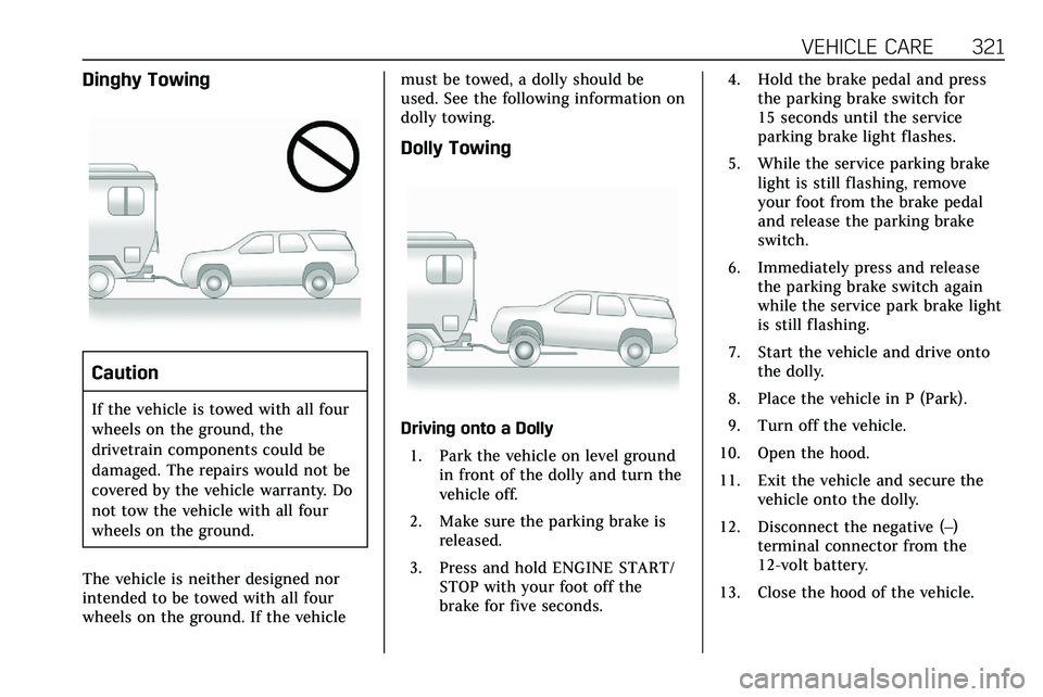
Dinghy Towing
Caution
If the vehicle is towed with all four
wheels on the ground, the
drivetrain components could be
damaged. The repairs would not be
covered by the vehicle warranty. Do
not tow the vehicle with all four
wheels on the ground.
The vehicle is neither designed nor
intended to be towed with all four
wheels on the ground. If the vehicle must be towed, a dolly should be
used. See the following information on
dolly towing.
Dolly Towing
Driving onto a Dolly
1. Park the vehicle on level ground in front of the dolly and turn the
vehicle off.
2. Make sure the parking brake is released.
3. Press and hold ENGINE START/ STOP with your foot off the
brake for five seconds. 4. Hold the brake pedal and press
the parking brake switch for
15 seconds until the service
parking brake light flashes.
5. While the service parking brake light is still flashing, remove
your foot from the brake pedal
and release the parking brake
switch.
6. Immediately press and release the parking brake switch again
while the service park brake light
is still flashing.
7. Start the vehicle and drive onto the dolly.
8. Place the vehicle in P (Park).
9. Turn off the vehicle.
10. Open the hood.
11. Exit the vehicle and secure the vehicle onto the dolly.
12. Disconnect the negative (–) terminal connector from the
12-volt battery.
13. Close the hood of the vehicle.