clock CADILLAC XT5 2020 Owner's Manual
[x] Cancel search | Manufacturer: CADILLAC, Model Year: 2020, Model line: XT5, Model: CADILLAC XT5 2020Pages: 384, PDF Size: 6.52 MB
Page 15 of 384
14 KEYS, DOORS, AND WINDOWS
driver door and turn the key
counterclockwise, to the unlock
position, five times within
10 seconds.
The DIC displays READY FOR
REMOTE #2, 3, 4, ETC.
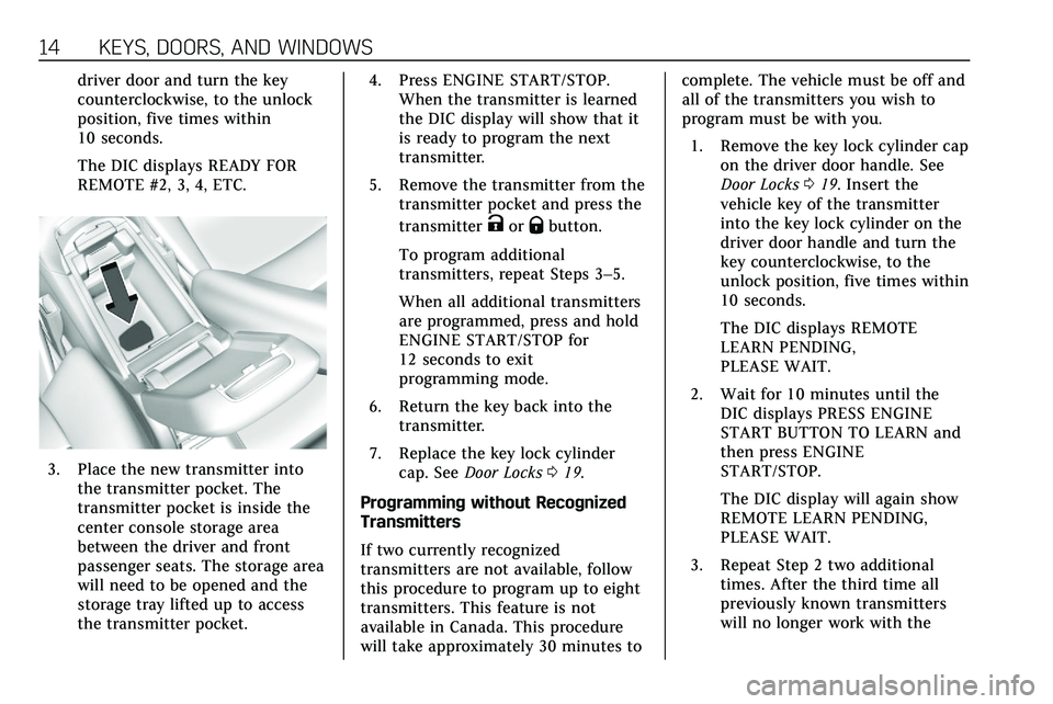
3. Place the new transmitter intothe transmitter pocket. The
transmitter pocket is inside the
center console storage area
between the driver and front
passenger seats. The storage area
will need to be opened and the
storage tray lifted up to access
the transmitter pocket. 4. Press ENGINE START/STOP.
When the transmitter is learned
the DIC display will show that it
is ready to program the next
transmitter.
5. Remove the transmitter from the transmitter pocket and press the
transmitter
KorQbutton.
To program additional
transmitters, repeat Steps 3–5.
When all additional transmitters
are programmed, press and hold
ENGINE START/STOP for
12 seconds to exit
programming mode.
6. Return the key back into the transmitter.
7. Replace the key lock cylinder cap. See Door Locks 019.
Programming without Recognized
Transmitters
If two currently recognized
transmitters are not available, follow
this procedure to program up to eight
transmitters. This feature is not
available in Canada. This procedure
will take approximately 30 minutes to complete. The vehicle must be off and
all of the transmitters you wish to
program must be with you.
1. Remove the key lock cylinder cap on the driver door handle. See
Door Locks 019. Insert the
vehicle key of the transmitter
into the key lock cylinder on the
driver door handle and turn the
key counterclockwise, to the
unlock position, five times within
10 seconds.
The DIC displays REMOTE
LEARN PENDING,
PLEASE WAIT.
2. Wait for 10 minutes until the DIC displays PRESS ENGINE
START BUTTON TO LEARN and
then press ENGINE
START/STOP.
The DIC display will again show
REMOTE LEARN PENDING,
PLEASE WAIT.
3. Repeat Step 2 two additional times. After the third time all
previously known transmitters
will no longer work with the
Page 100 of 384
INSTRUMENTS AND CONTROLS 99
Instruments and
Controls
Controls
Steering Wheel Adjustment . . . . . 100
Steering Wheel Controls . . . . . . . . . 100
Heated Steering Wheel . . . . . . . . . . 100
Horn . . . . . . . . . . . . . . . . . . . . . . . . . . . . . . . 100
Windshield Wiper/Washer . . . . . . . 101
Rear Window Wiper/Washer . . . . 103
Compass . . . . . . . . . . . . . . . . . . . . . . . . . . 104
Clock . . . . . . . . . . . . . . . . . . . . . . . . . . . . . . 104
Power Outlets . . . . . . . . . . . . . . . . . . . . . 104
Wireless Charging . . . . . . . . . . . . . . . . 105
Warning Lights, Gauges, and
Indicators
Warning Lights, Gauges, andIndicators . . . . . . . . . . . . . . . . . . . . . . . 107
Instrument Cluster . . . . . . . . . . . . . . . 108
Speedometer . . . . . . . . . . . . . . . . . . . . . . 111
Odometer . . . . . . . . . . . . . . . . . . . . . . . . . 111
Trip Odometer . . . . . . . . . . . . . . . . . . . . 111
Tachometer . . . . . . . . . . . . . . . . . . . . . . . 111
Fuel Gauge . . . . . . . . . . . . . . . . . . . . . . . . 112
Engine Coolant Temperature Gauge . . . . . . . . . . . . . . . . . . . . . . . . . . . . 112
Seat Belt Reminders . . . . . . . . . . . . . . 113 Airbag Readiness Light . . . . . . . . . . 114
Passenger Airbag Status
Indicator . . . . . . . . . . . . . . . . . . . . . . . . . 114
Charging System Light . . . . . . . . . . . 115
Malfunction Indicator Lamp (Check Engine Light) . . . . . . . . . . . 115
Brake System Warning Light . . . . 117
Electric Parking Brake Light . . . . . 118
Service Electric Parking Brake Light . . . . . . . . . . . . . . . . . . . . . . . . . . . . . 118
Antilock Brake System (ABS) Warning Light . . . . . . . . . . . . . . . . . . 118
Gear Shifting Light . . . . . . . . . . . . . . . 119
All-Wheel-Drive Light . . . . . . . . . . . . 119
Lane Keep Assist (LKA) Light . . . 119
Vehicle Ahead Indicator . . . . . . . . . 119
Pedestrian Ahead Indicator . . . . . . 120
Traction Off Light . . . . . . . . . . . . . . . . 120
StabiliTrak OFF Light . . . . . . . . . . . . 120
Traction Control System (TCS)/ StabiliTrak Light . . . . . . . . . . . . . . . . 121
Engine Coolant Temperature Warning Light . . . . . . . . . . . . . . . . . . 121
Driver Mode Control Light . . . . . . . 121
Tire Pressure Light . . . . . . . . . . . . . . . 122
Engine Oil Pressure Light . . . . . . . . 122
Low Fuel Warning Light . . . . . . . . . 123
Security Light . . . . . . . . . . . . . . . . . . . . . 123
High-Beam On Light . . . . . . . . . . . . . 123
Lamps On Reminder . . . . . . . . . . . . . 123 Cruise Control Light . . . . . . . . . . . . . . 124
Door Ajar Light . . . . . . . . . . . . . . . . . . . 124
Information Displays
Driver Information
Center (DIC) . . . . . . . . . . . . . . . . . . . . . 124
Head-Up Display (HUD) . . . . . . . . . 127
Vehicle Messages
Vehicle Messages . . . . . . . . . . . . . . . . . 130
Engine Power Messages . . . . . . . . . . 131
Vehicle Speed Messages . . . . . . . . . 131
Vehicle Personalization
Vehicle Personalization . . . . . . . . . . 131
Universal Remote System
Universal Remote System . . . . . . . . 137
Universal Remote System Programming . . . . . . . . . . . . . . . . . . . 137
Universal Remote System Operation . . . . . . . . . . . . . . . . . . . . . . . . 139
Page 105 of 384
104 INSTRUMENTS AND CONTROLS
windshield wiper is performing low or
high speed wipes. If the rear wiper
control is off, the transmission is in
R (Reverse), and the front windshield
wiper is performing INT wipes, then
the rear wiper automatically performs
INT wipes.
This feature can be turned on or off.
SeeVehicle Personalization 0131.
The windshield washer reservoir is
used for the windshield, rear window,
and rear mirror camera, if equipped.
See Rear Camera Mirror 035. Check
the fluid level in the reservoir if either
washer is not working. See Washer
Fluid 0266.
Rear Camera Washer
If equipped, push the windshield
wiper lever forward to spray washer
fluid on the rear camera and the
Night Vision camera lens. The lever
returns to its starting position when
released. See Rear Camera Mirror 035.
Compass
The vehicle may have a compass
display on the Driver Information
Center (DIC). The compass receives its
heading and other information from
the Global Positioning System (GPS)
antenna, StabiliTrak/Electronic
Stability Control (ESC), and vehicle
speed information.
The compass system is designed to
operate for a certain number of miles
or degrees of turn before needing a
signal from the GPS satellites. When
the compass display shows CAL, drive
the vehicle for a short distance in an
open area where it can receive a GPS
signal. The compass system will
automatically determine when a GPS
signal is restored and provide a
heading again.
Clock
The time and date for the clock can be
set using the infotainment system. See
“Time/Date ”in “System ”under
“Settings ”in the infotainment manual.
Power Outlets
The accessory power outlet can be
used to plug in electrical equipment,
such as a cell phone or MP3 player.
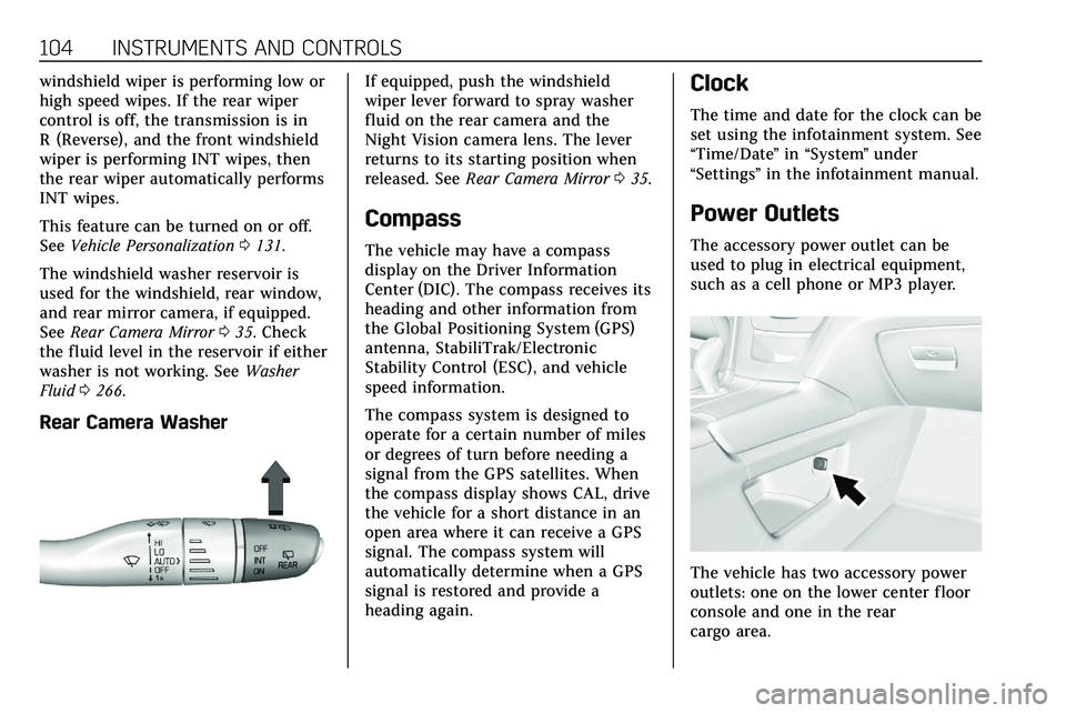
The vehicle has two accessory power
outlets: one on the lower center floor
console and one in the rear
cargo area.
Page 264 of 384

VEHICLE CARE 263
How to Add Coolant to the
Surge Tank
{Warning
Spilling coolant on hot engine parts
can burn you. Coolant contains
ethylene glycol and it will burn if
the engine parts are hot enough.
{Warning
Steam and scalding liquids from a
hot cooling system are under
pressure. Turning the pressure cap,
even a little, can cause them to
come out at high speed and you
could be burned. Never turn the cap
when the cooling system, including
the pressure cap, is hot. Wait for
the cooling system and pressure
cap to cool.
Caution
Failure to follow the specific
coolant fill procedure could cause
the engine to overheat and could
cause system damage. If coolant is
not visible in the surge tank,
contact your dealer.
The coolant surge tank pressure cap
can be removed when the cooling
system, including the surge tank
pressure cap and upper radiator hose,
is no longer hot.
Coolant Fill Instructions (3.6L
Engine Only)
1. Turn the pressure cap slowly counterclockwise. If a hiss is
heard, wait for that to stop.
A hiss means there is still some
pressure left. 2. Keep turning the pressure cap
slowly and remove it.
3. Fill the coolant surge tank withthe proper mixture to the mark
pointed to on the front of the
coolant surge tank.
4. With the coolant surge tank pressure cap off, start the engine
and let it run until you can feel
the upper radiator hose getting
hot. Watch out for the engine
cooling fans. By this time, the
coolant level inside the coolant
surge tank may be lower. If the
level is lower, add more of the
proper mixture to the coolant
Page 306 of 384

VEHICLE CARE 305
2. Sealant/Air Hose
3. Base of Sealant Canister
4. Tire Sealant Canister
5. On/Off Button
6. Slot on Top of Compressor
7. Pressure Deflation Button
8. Pressure Gauge
9. Power Plug
10. Air Only Hose
Tire Sealant
Read and follow the safe handling
instructions on the label adhered to
the tire sealant canister (4).Check the tire sealant expiration date
on the tire sealant canister. The tire
sealant canister (4) should be replaced
before its expiration date.
Replacement tire sealant canisters are
available at your local dealer.
There is only enough sealant to seal
one tire. After usage, the tire sealant
canister must be replaced.
Using the Tire Sealant and
Compressor Kit to Temporarily
Seal and Inflate a
Punctured Tire
When using the tire sealant and
compressor kit during cold
temperatures, warm the kit in a
heated environment for five minutes.
This will help to inflate the tire faster.
If a tire goes flat, avoid further tire
and wheel damage by driving slowly
to a level place. Turn on the hazard
warning flashers. See
Hazard Warning
Flashers 0143.
See If a Tire Goes Flat 0302 for other
important safety warnings.
Do not remove any objects that have
penetrated the tire. 1. Remove the tire sealant
canister (4) and compressor from
its storage location. See Storing
the Tire Sealant and Compressor
Kit 0310.
2. Remove the air only hose (10) and the power plug (9) from the
bottom of the compressor.
3. Place the compressor on the ground near the flat tire.
4. Attach the air only hose (10) tothe sealant canister inlet
valve (1) by turning it clockwise
until tight.
Page 307 of 384
306 VEHICLE CARE
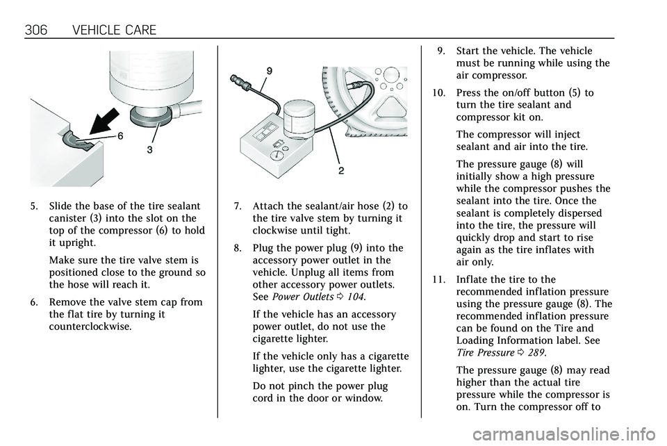
5. Slide the base of the tire sealantcanister (3) into the slot on the
top of the compressor (6) to hold
it upright.
Make sure the tire valve stem is
positioned close to the ground so
the hose will reach it.
6. Remove the valve stem cap from the flat tire by turning it
counterclockwise.7. Attach the sealant/air hose (2) tothe tire valve stem by turning it
clockwise until tight.
8. Plug the power plug (9) into the accessory power outlet in the
vehicle. Unplug all items from
other accessory power outlets.
See Power Outlets 0104.
If the vehicle has an accessory
power outlet, do not use the
cigarette lighter.
If the vehicle only has a cigarette
lighter, use the cigarette lighter.
Do not pinch the power plug
cord in the door or window. 9. Start the vehicle. The vehicle
must be running while using the
air compressor.
10. Press the on/off button (5) to turn the tire sealant and
compressor kit on.
The compressor will inject
sealant and air into the tire.
The pressure gauge (8) will
initially show a high pressure
while the compressor pushes the
sealant into the tire. Once the
sealant is completely dispersed
into the tire, the pressure will
quickly drop and start to rise
again as the tire inflates with
air only.
11. Inflate the tire to the recommended inflation pressure
using the pressure gauge (8). The
recommended inflation pressure
can be found on the Tire and
Loading Information label. See
Tire Pressure 0289.
The pressure gauge (8) may read
higher than the actual tire
pressure while the compressor is
on. Turn the compressor off to
Page 308 of 384

VEHICLE CARE 307
get an accurate pressure reading.
The compressor may be turned
on/off until the correct pressure
is reached.
Caution
If the recommended pressure
cannot be reached after
approximately 25 minutes, the
vehicle should not be driven farther.
The tire is too severely damaged
and the tire sealant and compressor
kit cannot inflate the tire. Remove
the power plug from the accessory
power outlet and unscrew the
inflating hose from the tire valve.
SeeRoadside Service 0353.
12. Press the on/off button (5) to turn the tire sealant and
compressor kit off.
The tire is not sealed and will
continue to leak air until the
vehicle is driven and the sealant
is distributed in the tire.
Therefore, Steps 13–21 must be
done immediately after Step 12. Be careful while handling the tire
sealant and compressor kit as it
could be warm after usage.
13. Unplug the power plug (9) from the accessory power outlet in the
vehicle.
14. Turn the sealant/air hose (2) counterclockwise to remove it
from the tire valve stem.
15. Replace the tire valve stem cap.
16. Remove the tire sealant canister (4) from the slot on top
of the compressor (6).
17. Turn the air only hose (10) counterclockwise to remove it
from the tire sealant canister
inlet valve (1).
18. Turn the sealant/air hose (2) clockwise onto the sealant
canister inlet valve (1) to prevent
sealant leakage.
19. Return the air only hose (10) and power plug (9) back to their
original storage location.20. If the flat tire was able to inflateto the recommended inflation
pressure, remove the maximum
speed label from the sealant
canister and place it in a highly
visible location.
Do not exceed the speed on this
label until the damaged tire is
repaired or replaced.
21. Return the equipment to its original storage location in the
vehicle.
22. Immediately drive the vehicle 8 km (5 mi) to distribute the
sealant in the tire.
23. Stop at a safe location and check the tire pressure. Refer to
Steps 1–10 under “Using the Tire
Sealant and Compressor Kit
without Sealant to Inflate a Tire
(Not Punctured).”
Page 310 of 384
VEHICLE CARE 309
3. Place the compressor on theground near the flat tire.
Make sure the tire valve stem is
positioned close to the ground so
the hose will reach it.
4. Remove the valve stem cap from the flat tire by turning it
counterclockwise.
5. Attach the air only hose (10) to the tire valve stem by turning it
clockwise until tight.
6. Plug the power plug (9) into the accessory power outlet in the
vehicle. Unplug all items from
other accessory power outlets.
See Power Outlets 0104.
If the vehicle has an accessory
power outlet, do not use the
cigarette lighter.
If the vehicle only has a cigarette
lighter, use the cigarette lighter.
Do not pinch the power plug
cord in the door or window.
7. Start the vehicle. The vehicle must be running while using the
air compressor. 8. Press the on/off button (5) to
turn the tire sealant and
compressor kit on.
The compressor will inflate the
tire with air only.
9. Inflate the tire to the recommended inflation pressure
using the pressure gauge (8). The
recommended inflation pressure
can be found on the Tire and
Loading Information label. See
Tire Pressure 0289.
The pressure gauge (8) may read
higher than the actual tire
pressure while the compressor is
on. Turn the compressor off to
get an accurate pressure reading.
The compressor may be turned
on/off until the correct pressure
is reached.
Caution
If the recommended pressure
cannot be reached after
approximately 25 minutes, the
vehicle should not be driven farther. (Continued)
Caution (Continued)
The tire is too severely damaged
and the tire sealant and compressor
kit cannot inflate the tire. Remove
the power plug from the accessory
power outlet and unscrew the
inflating hose from the tire valve.
SeeRoadside Service 0353.
10. Press the on/off button (5) to turn the tire sealant and
compressor kit off.
Be careful while handling the
compressor as it could be warm
after usage.
11. Unplug the power plug (9) from the accessory power outlet in the
vehicle.
12. Turn the air only hose (10) counterclockwise to remove it
from the tire valve stem.
13. Replace the tire valve stem cap.
14. Return the air only hose (10) and power plug (9) back to their
original storage location.
Page 311 of 384

310 VEHICLE CARE
15. Return the equipment to itsoriginal storage location in the
vehicle.
The tire sealant and compressor kit
has accessory adapters located in a
compartment on the bottom of its
housing that can be used to inflate air
mattresses, balls, etc.
Storing the Tire Sealant
and Compressor Kit
The tire sealant and compressor kit is
in a bag in the rear compartment
storage area. 1. Open the liftgate.
2. Remove the cargo management system divider. See Cargo
Management System 096.
3. Lift the load floor. Use the hook to hold the load floor open. See
Rear Storage 093.4. Turn the retainer nut
counterclockwise to remove the
tire sealant and compressor
kit bag.
5. Remove the tire sealant and compressor kit from the bag.
To store the tire sealant and
compressor kit, reverse the steps.
Tire Changing
Removing the Spare Tire and
Tools
To access the spare tire and tools: 1. Open the liftgate. See Liftgate
0 23. 2. Remove the cargo management
system divider. See Cargo
Management System 096.
3. Pull up on the handle to lift the
load floor. Use the hook to hold
the load floor open. See Rear
Storage 093.
Page 312 of 384

VEHICLE CARE 311
4. Turn the wing nut (4)counterclockwise to remove the
jack (1), wheel wrench (2), and
strap (3). Place the tool container
near the tire being changed.5. Remove the nut retaining thespare tire.
6. Remove the spare tire and place it next to the tire being changed.
Removing the Flat Tire and
Installing the Spare Tire
1. Do a safety check beforeproceeding. See If a Tire Goes Flat
0 302.
2. Turn the wheel wrench
counterclockwise to loosen all
the wheel nuts, but do not
remove them yet.
3. Place the jack near the flat tire.
Caution
Make sure that the jack lift head is
in the correct position or you may
damage your vehicle. The repairs
would not be covered by your
warranty.