wheel size CHERY TIGGO 2009 Service Repair Manual
[x] Cancel search | Manufacturer: CHERY, Model Year: 2009, Model line: TIGGO, Model: CHERY TIGGO 2009Pages: 1903, PDF Size: 33.38 MB
Page 1340 of 1903
Downloaded from www.Manualslib.com manuals search engine GENERAL INFORMATION
Description
Vehicle wheel alignment is the positioning of all interrelated front and rear suspension angles. These angles affect the
handling and steering of the vehicle when it is in motion. Proper wheel alignment is essential for efficient steering,
good directional stability, and proper tire wear.
The method of checking a vehicle’s front and rear wheel alignment varies depending on the manufacturer and type
of equipment used. The manufacturer’s instructions should always be followed to ensure accuracy of the alignment.
On this vehicle, the suspension angles that can be adjusted are as follows:
Front Axle
•Camber
• Caster
• Toe-in
Rear Axle
• Camber
• Toe-in
Check the wheel alignment and make all wheel alignment adjustments with the vehicle standing at its proper curb
height specification. Curb height is the normal riding height of the vehicle. It is measured from a certain point on the
vehicle to the ground or a designated area while the vehicle is sitting on a flat, level surface.
Operation
Curb Height Measurement
The wheel alignment is to be checked and all alignment adjustments made with the vehicle at its required curb height
specification.
• Vehicle height is to be checked with the vehicle on a flat, level surface, preferably a vehicle alignment rack.
• The tires are to be inflated to the recommended pressure.
• All tires are to be the same size as standard equipment.
• Vehicle height is checked with the fuel tank full of fuel, and no passenger or luggage compartment load.
• Vehicle height is not adjustable.
• If the measurement is not within specifications, inspect the vehicle for bent or weak suspension components.
• Compare the parts tag on the suspect coil spring(s) to the parts book and the vehicle sales code, checking for
a match.
• Once removed from the vehicle, compare the coil spring height to a new or known good coil spring. The
heights should vary if the suspect spring is weak.
NOTE :
Prior to reading the curb height measurement, the front and rear of the vehicle must be jounced to settle the sus-
pension. Induce jounce by pushing down on the center of the bumper (fascia), using care not to damage the vehicle,
moving the vehicle up and down, gradually increasing the suspension travel with each stroke. Release the bumper at
the bottom of each stroke, repeating this action several times. Perform this to both front and rear suspensions an
equal number of times.
Pre-Wheel Alignment Inspection
Before any attempt is made to change or correct the wheel alignment, the following inspection and necessary cor-
rections must be made to the vehicle to ensure proper alignment. 1. Verify the fuel tank is full of fuel. If the fuel tank is not full, the reduction in weight will affect the curb height of the vehicle and the alignment specifications.
2. The passenger and luggage compartments of the vehicle should be free of any load that is not factory equip- ment.
10
10–39Chery Automobile Co., Ltd.
Page 1341 of 1903
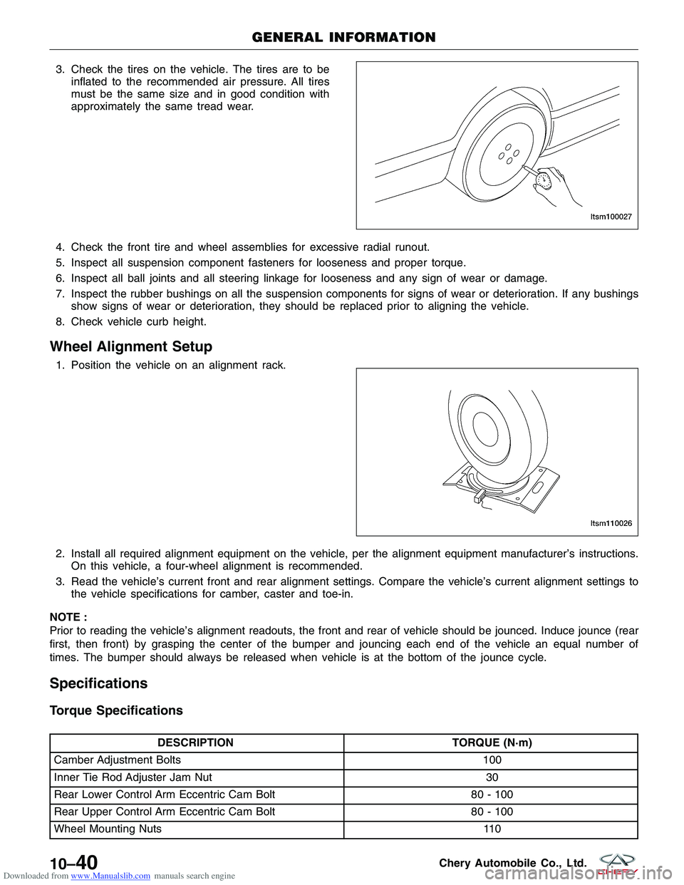
Downloaded from www.Manualslib.com manuals search engine 3. Check the tires on the vehicle. The tires are to beinflated to the recommended air pressure. All tires
must be the same size and in good condition with
approximately the same tread wear.
4. Check the front tire and wheel assemblies for excessive radial runout.
5. Inspect all suspension component fasteners for looseness and proper torque.
6. Inspect all ball joints and all steering linkage for looseness and any sign of wear or damage.
7. Inspect the rubber bushings on all the suspension components for signs of wear or deterioration. If any bushings show signs of wear or deterioration, they should be replaced prior to aligning the vehicle.
8. Check vehicle curb height.
Wheel Alignment Setup
1. Position the vehicle on an alignment rack.
2. Install all required alignment equipment on the vehicle, per the alignment equipment manufacturer’s instructions. On this vehicle, a four-wheel alignment is recommended.
3. Read the vehicle’s current front and rear alignment settings. Compare the vehicle’s current alignment settings to the vehicle specifications for camber, caster and toe-in.
NOTE :
Prior to reading the vehicle’s alignment readouts, the front and rear of vehicle should be jounced. Induce jounce (rear
first, then front) by grasping the center of the bumper and jouncing each end of the vehicle an equal number of
times. The bumper should always be released when vehicle is at the bottom of the jounce cycle.
Specifications
Torque Specifications
DESCRIPTION TORQUE (N·m)
Camber Adjustment Bolts 100
Inner Tie Rod Adjuster Jam Nut 30
Rear Lower Control Arm Eccentric Cam Bolt 80 - 100
Rear Upper Control Arm Eccentric Cam Bolt 80 - 100
Wheel Mounting Nuts 110
GENERAL INFORMATION
LTSM100027
LTSM110026
10–40Chery Automobile Co., Ltd.
Page 1349 of 1903
Downloaded from www.Manualslib.com manuals search engine GENERAL INFORMATION
Description
Tires are designed and engineered for each specific vehicle. They provide the best overall performance for normal
operation. The ride and handling characteristics match the vehicle’s requirements. With proper care they will give
excellent reliability, traction, skid resistance, and tread life.
Tire Identification
•Tire type, size, load index and speed rating are encoded in the letters and numbers imprinted on the side wall
of the tire.
Spare Tire
• A full size spare tire and wheel assembly is standard equipment on this vehicle. The original tire should be
repaired or replaced at the first opportunity, then reinstalled.
Operation
Driving habits have more effect on tire life than any other factor. Careful drivers will obtain, in most cases, much
greater mileage than severe use or careless drivers. A few of the driving habits which will shorten the life of any tire
are:
•Rapid acceleration
• Severe application of brakes
• High-speed driving
• Taking turns at excessive speeds
• Striking curbs and other obstacles
• Operating vehicle with over or under inflated tire pressures
Specifications
Torque Specifications
DESCRIPTION TORQUE (N·m)
Wheel Mounting Nuts 110
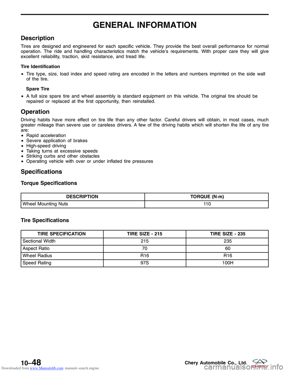
Tire Specifications
TIRE SPECIFICATIONTIRE SIZE - 215TIRE SIZE - 235
Sectional Width 215235
Aspect Ratio 7060
Wheel Radius R16R16
Speed Rating 97S100H
10–48Chery Automobile Co., Ltd.
Page 1352 of 1903
Downloaded from www.Manualslib.com manuals search engine ON-VEHICLE SERVICE
Tire Repair
Description
Tires are designed and engineered for each specific vehicle. They provide the best overall performance for normal
operation. The ride and handling characteristics match the vehicle’s requirements. With proper care they will give
excellent reliability, traction, skid resistance, and tread life.
WARNING!
Failure to equip the vehicle with tires having adequate speed capability can result in sudden tire failure.
In order to maintain the speed capability of the vehicle, replacement tires must have speed ratings equal to or
higher than those fitted to the vehicle as original equipment. If tires with lower speed ratings are fitted, the vehi-
cle’s handling may be affected and the speed capability of the vehicle may be lowered to the maximum speed
capability of the replacement tires. To avoid an accident resulting in severe or fatal injury, consult the tire man-
ufacturer in regards to maximum speed ratings.
Replacement Procedure
Note the following guidelines when replacing a tire:
•It is recommended that tires equivalent to the original equipment tires be used when replacement is needed.
• Failure to use equivalent replacement tires may adversely affect the safety and handling of the vehicle.
• The use of tires smaller than the minimum tire size approved for the vehicle can result in tire overloading and
failure.
• Use tires that have the approved load rating for the vehicle and never overload them.
• Failure to equip the vehicle with tires having adequate speed capability can result in sudden tire failure and
loss of vehicle control.
• The use of oversize tires may cause interference with vehicle components. Under extremes of suspension and
steering travel, interference with vehicle components may cause tire damage.
Perform the following when replacing a tire: 1. Raise and support the vehicle.
2. Remove the wheel mounting nuts and the wheel assembly.
3. Deflate the tire completely before removing the tire from the wheel.
4. Use lubrication such as a mild soap solution when dismounting or mounting tire.
5. Replace the tire with a tire approved for the vehicle.
6. Use tools free of burrs or sharp edges which could damage the tire or wheel rim.
7. Before mounting tire on wheel, make sure all rust is removed from the rim bead and repaint if necessary.
8. Balance the wheel assembly.
9. Install the wheel assembly and install the wheel mounting nuts. (Tighten: Wheel mounting nuts to 110 N·m)
Repair Procedure
Note the following guidelines when performing a tire repair:
•For proper repairing, a radial tire must be removed from the wheel.
• Repairs should only be made if the defect, or puncture, is in the tread area.
• The tire should be replaced if the puncture is located in the sidewall.
Perform the following when repairing a tire: 1. Raise and support the vehicle.
2. Remove the wheel mounting nuts and the wheel assembly.
3. Deflate the tire completely before removing the tire from the wheel.
4. Use lubrication such as a mild soap solution when dismounting or mounting tire.
5. Repair the tire only if the defect, or puncture, is in the tread area.
6. Use tools free of burrs or sharp edges which could damage the tire or wheel rim.
7. Before mounting tire on wheel, make sure all rust is removed from the rim bead and repaint if necessary.
10–51Chery Automobile Co., Ltd.
Page 1388 of 1903
Downloaded from www.Manualslib.com manuals search engine DIAGNOSIS & TESTING
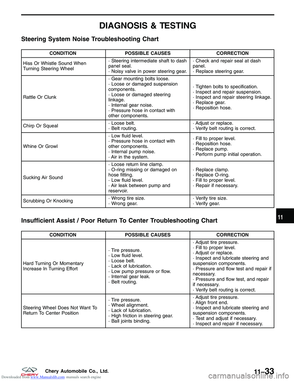
Steering System Noise Troubleshooting Chart
CONDITIONPOSSIBLE CAUSES CORRECTION
Hiss Or Whistle Sound When
Turning Steering Wheel · Steering intermediate shaft to dash
panel seal.
· Noisy valve in power steering gear.· Check and repair seal at dash
panel.
· Replace steering gear.
Rattle Or Clunk · Gear mounting bolts loose.
· Loose or damaged suspension
components.
· Loose or damaged steering
linkage.
· Internal gear noise.
· Pressure hose in contact with
other components.· Tighten bolts to specification.
· Inspect and repair suspension.
· Inspect and repair steering linkage.
· Replace gear.
· Reposition hose.
Chirp Or Squeal · Loose belt.
· Belt routing.· Adjust or replace.
· Verify belt routing is correct.
Whine Or Growl · Low fluid level.
· Pressure hose in contact with
other components.
· Internal pump noise.
· Air in the system.· Fill to proper level.
· Reposition hose.
· Replace pump.
· Perform pump initial operation.
Sucking Air Sound · Loose return line clamp.
· O-ring missing or damaged on
hose fitting.
· Low fluid level.
· Air leak between pump and
reservoir.· Replace clamp.
· Replace O-ring.
· Fill to proper level.
· Repair if necessary.
Scrubbing Or Knocking · Wrong tire size.
· Wrong gear.· Verify tire size.
· Verify gear.
Insufficient Assist / Poor Return To Center Troubleshooting Chart
CONDITION
POSSIBLE CAUSES CORRECTION
Hard Turning Or Momentary
Increase In Turning Effort · Tire pressure.
· Low fluid level.
· Loose belt.
· Lack of lubrication.
· Low pump pressure or flow.
· Internal gear leak.
· Belt routing.· Adjust tire pressure.
· Fill to proper level.
· Adjust or replace.
· Inspect and lubricate steering and
suspension components.
· Pressure and flow test and repair if
necessary.
· Pressure and flow test, and repair
if necessary.
· Verify belt routing is correct.
Steering Wheel Does Not Want To
Return To Center Position · Tire pressure.
· Wheel alignment.
· Lack of lubrication.
· High friction in steering gear.
· Ball joints binding.· Adjust tire pressure.
· Align front end.
· Inspect and lubricate steering and
suspension components.
· Test and adjust if necessary.
· Inspect and repair if necessary.
11
11 –33Chery Automobile Co., Ltd.
Page 1477 of 1903
Downloaded from www.Manualslib.com manuals search engine DIAGNOSIS & TESTING
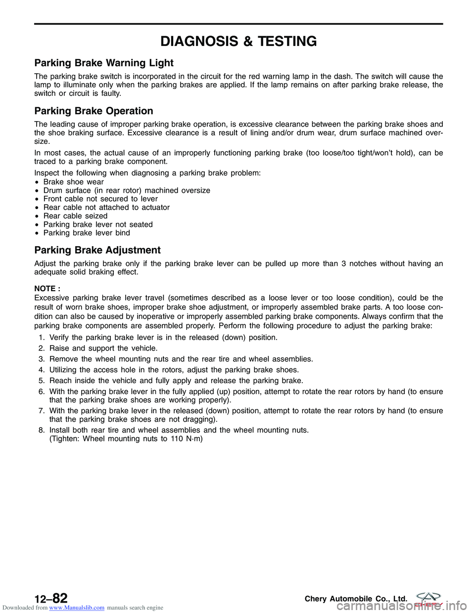
Parking Brake Warning Light
The parking brake switch is incorporated in the circuit for the red warning lamp in the dash. The switch will cause the
lamp to illuminate only when the parking brakes are applied. If the lamp remains on after parking brake release, the
switch or circuit is faulty.
Parking Brake Operation
The leading cause of improper parking brake operation, is excessive clearance between the parking brake shoes and
the shoe braking surface. Excessive clearance is a result of lining and/or drum wear, drum surface machined over-
size.
In most cases, the actual cause of an improperly functioning parking brake (too loose/too tight/won’t hold), can be
traced to a parking brake component.
Inspect the following when diagnosing a parking brake problem:
•Brake shoe wear
• Drum surface (in rear rotor) machined oversize
• Front cable not secured to lever
• Rear cable not attached to actuator
• Rear cable seized
• Parking brake lever not seated
• Parking brake lever bind
Parking Brake Adjustment
Adjust the parking brake only if the parking brake lever can be pulled up more than 3 notches without having an
adequate solid braking effect.
NOTE :
Excessive parking brake lever travel (sometimes described as a loose lever or too loose condition), could be the
result of worn brake shoes, improper brake shoe adjustment, or improperly assembled brake parts. A too loose con-
dition can also be caused by inoperative or improperly assembled parking brake components. Always confirm that the
parking brake components are assembled properly. Perform the following procedure to adjust the parking brake:
1. Verify the parking brake lever is in the released (down) position.
2. Raise and support the vehicle.
3. Remove the wheel mounting nuts and the rear tire and wheel assemblies.
4. Utilizing the access hole in the rotors, adjust the parking brake shoes.
5. Reach inside the vehicle and fully apply and release the parking brake.
6. With the parking brake lever in the fully applied (up) position, attempt to rotate the rear rotors by hand (to ensure that the parking brake shoes are working properly).
7. With the parking brake lever in the released (down) position, attempt to rotate the rear rotors by hand (to ensure that the parking brake shoes are not dragging).
8. Install both rear tire and wheel assemblies and the wheel mounting nuts. (Tighten: Wheel mounting nuts to 110 N·m)
12–82Chery Automobile Co., Ltd.