headlights CHEVROLET CAMARO 1967 1.G Chassis Workshop Manual
[x] Cancel search | Manufacturer: CHEVROLET, Model Year: 1967, Model line: CAMARO, Model: CHEVROLET CAMARO 1967 1.GPages: 659, PDF Size: 114.24 MB
Page 335 of 659

ENGINE-ELECTRICAL 6Y-10
circuit. Make absolutely certain all connections in
the circuit are secure.
5.
Do not short across or ground any of the terminals
on the generator or regulator.
6. Do not attempt to polarize the generator.
7.
Do not disconnect lead at generator without first dis-
connecting battery ground cable.
Trouble in the A.C. charging system will usually be
indicated by one or more of the following conditions:
1.
Faulty indicator lamp or ammeter operation.
2.
An undercharged battery (usually evidenced by slow
cranking speeds).
3.
An overcharged battery (usually evidenced by exces-
sive battery water usage).
4.
Excessive generator noise or vibration.
Described below are a series of on-the-vehicle quick
checks which are designed to assist the service tech-
nician in locating troubles within the various components
of the engine electrical system. Additional checks, ad-
justments and overhaul procedures of these components
are also described in the "Charging Systems—Service
Operations Section" and should be referred to as
necessary.
STATIC CHECKS
Before making any electrical checks, perform the fol-
lowing static checks:
1.
Check for loose fan belt.
2.
Check for defective battery. (Refer to Battery).
3.
Inspect all connections, including the slip-on con-
nectors at the regulator and Delcotron.
NOTE: Do not short field to ground to check if
generator is charging since this will seriously
damage the charging system.
SYSTEM CONDITION TEST
This test is used .to indicate the overall condition of the
charging system (both good and defective) and to isolate
the malfunctioning unit if the system is defective.
NOTE: On Corvette models difficulty may be
encountered -when attempting to make the re-
quired test connections at the voltage regulator.
It is advisable to remove the regulator from its
mounting location to perform the necessary con-
nections at the regulator for the following tests
but make sure unit is grounded.
1.
With ignition off, perform the prescribed Static
Checks outlined in this section. Then set hand brake
and shift transmission
into
neutral.
2.
Connect a voltmeter from junction block relay to
ground at regulator base.
CAUTION: Be sure meter clip does not touch a
resistor or terminal extension under regulator,
3.
Connect a tachometer on engine.
4.
Models equipped with Indicator Lamp: Turn ignition
switch on "ON" position and check indicator lamp.
If lamp fails to glow, perform appropriate tests and
corrections (Indicator Lamp Circuit Tests) before
continuing.
Models equipped with Ammeter: Turn ignition
switch to "ACC" with an accessory on and check
ammeter. If ammeter fails to read discharge, check
ammeter circuit before continuing.
5.
Models equipped with Indicator Lamp: If lamp glows,
start the engine and run' it at 1500 rpm or above.
Check indicator lamp. If lamp fails to go out, per-
form appropriate test and corrections (Indicator
Lamp Circuit Test) before continuing.
Models equipped with Ammeter: If ammeter reads
discharge, start the engine and observe ammeter. If
meter fails to move toward charge (from original
position), perform appropriate test and corrections
(Field Circuit Tests) before continuing.
NOTE: At this point a field circuit has been
established and any other problem will lie in
generator or regulator.
6. Turn on high-beam headlights and heater blower
motor to high speed, run engine at or above 1500
rpm (for a few minutes, if necessary) and read the
voltage on meter.
AIR GAP
ADJUSTING NUT
ONLY
ADJUSTING SCREW
(Turn To Adjust
Voltage Setting)
Fig.
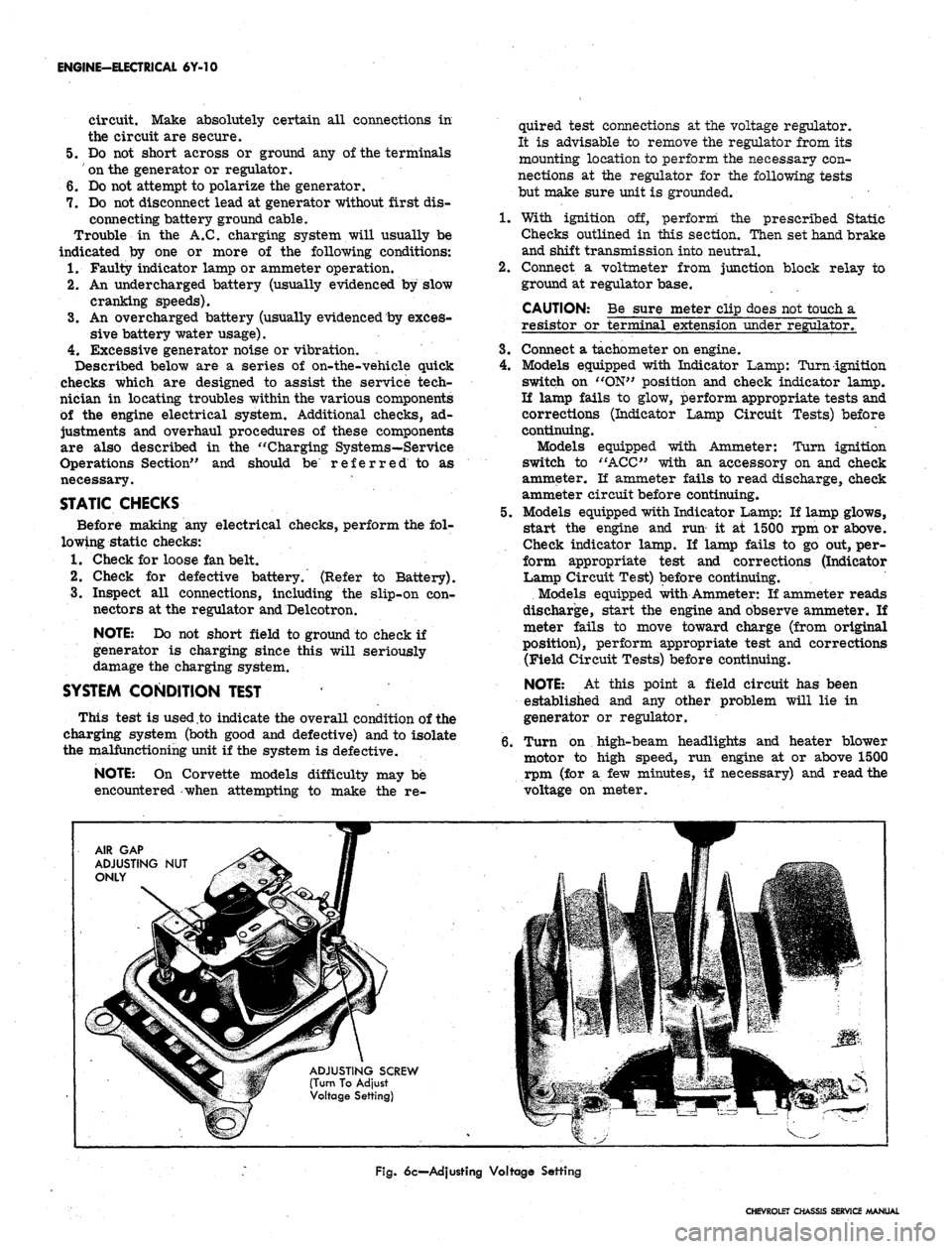
6c—Adjusting Voltage Setting
CHEVROLET CHASSIS SERVICE MANUAL
Page 528 of 659

ELECTRICAL-BODY AND CHASSIS 12-16
BACK-UP LAMP CONN.
CONSOLE CTSY
LAMP CONN
CLOCK CONN
NEUTRAL SAFETY SWITCH
Fig.
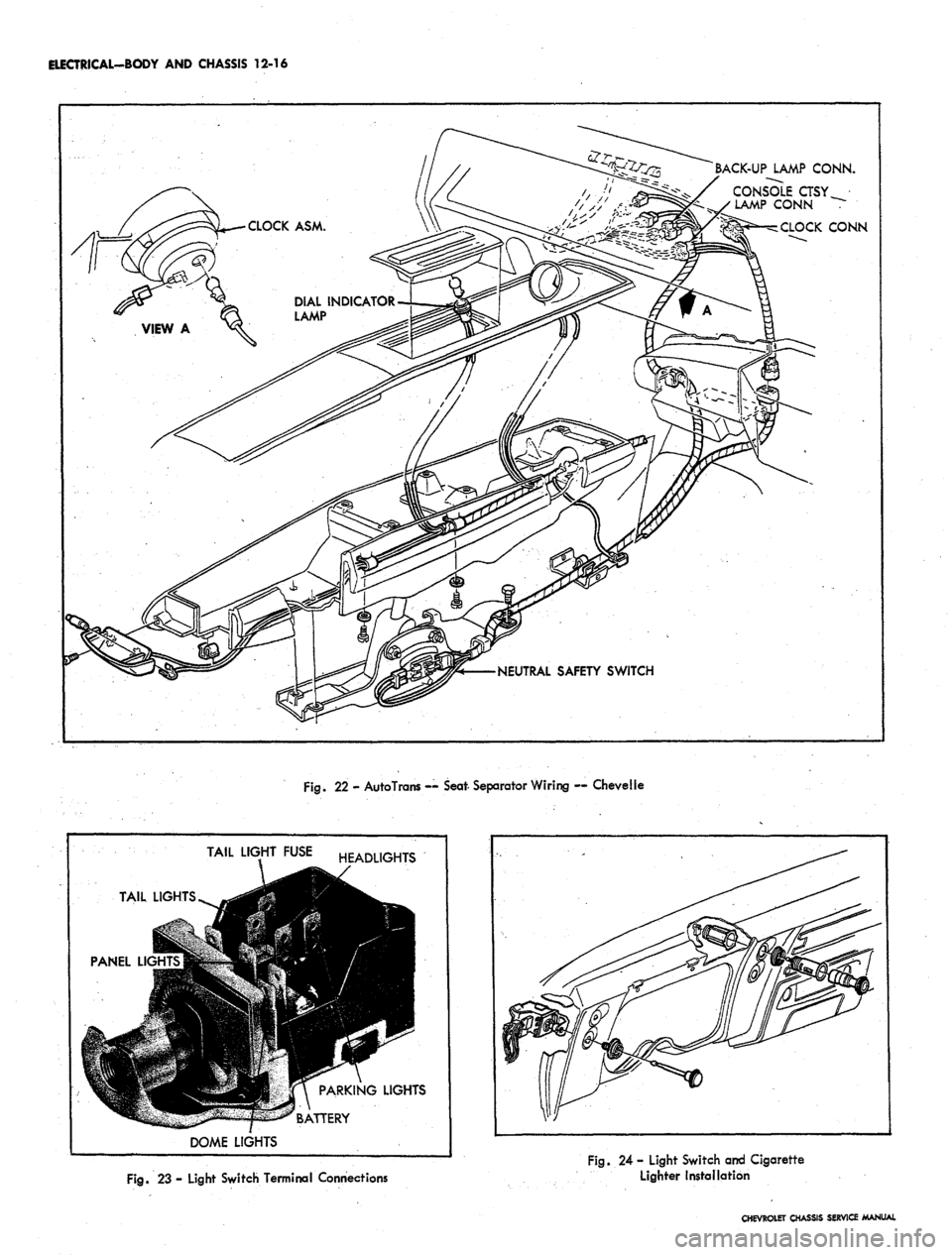
22 - AutoTrans — Seat- Separator Wiring — Chevelle
TAIL
PANEL Ll<
J
TAIL
LIGHTS ^^g
9
""TUtflll -^ ""
DOME
LIGHT
r
•I
m
/
LIGHTS
FUSE HEADLIGHTS
9R
jl PARKING LIGHTS
*^ R ATTPRY
Fig.
23 - Light Switch Terminal Connections
Fig.
24 - Light Switch and Cigarette
Lighter Installation
CHEVROLET CHASSIS SERVICE MANUAL