length CHEVROLET CAMARO 1967 1.G Chassis Workshop Manual
[x] Cancel search | Manufacturer: CHEVROLET, Model Year: 1967, Model line: CAMARO, Model: CHEVROLET CAMARO 1967 1.GPages: 659, PDF Size: 114.24 MB
Page 3 of 659
SECTION O
INFORMATION AND LUBRICATION
CONTENTS OF THIS SECTION
Page
General Information o-l
Lubrication 0-13
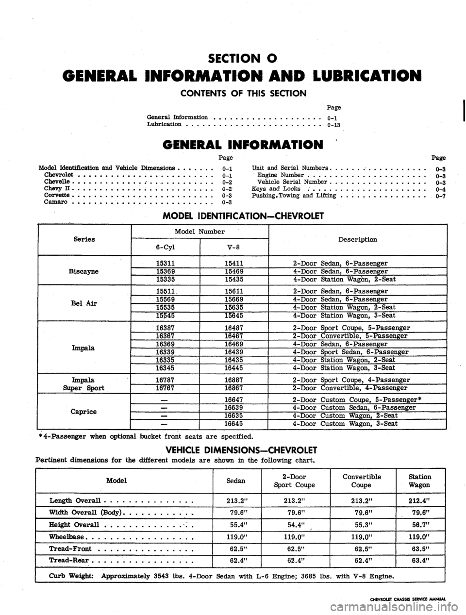
GENERAL INFORMATION
Model Identification and Vehicle Dimensions
Chevrolet
Chevelle
Chevy n
Corvette
Camaro
Page
0-1
0-1
0-2
0-2
0-3
0-3
Page
Unit and Serial Numbers o-3
Engine Number o-3
Vehicle Serial Number 0r3
Keys and Locks 0-4
Pushing,Towing and Lifting 0-7
Series
Biscayne
Bel Air
Tmpala.
Impala
Super Sport
Caprice
MODEL IDENTIFICATION-CHEVROLET
Model Number
6-Cyl
15311
15369
15335
15511,
15569
15535
15545
16387
16367
16369
16339
16335
16345
16787
16767
—
—
—
—
V-8
15411
15469
15435
15611
15669
15635
15645
16487
16467
16469
16439
16435
16445
16887
16867
16647
16639
16635
16645
Description
2-Door Sedan, 6-Passenger
4-Door Sedan, 6-Passenger
4-Door Station Wagon, 2-Seat
2-Door Sedan, 6-Passenger
4-Door Sedan, 6-Passenger
4-Door Station Wagon, 2-Seat
4-Door Station Wagon, 3-Seat
2-Door Sport Coupe, 5-Passenger
2-Door Convertible, 5-Passenger
4-Door Sedan, 6-Passenger
4-Door Sport Sedan, 6-Passenger
4-Door Station Wagon, 2-Seat
4-Door Station Wagon, 3-Seat
2-Door Sport Coupe, 4-Passenger
2-Door Convertible, 4-Passenger
2-Door Custom Coupe, 5-Passenger*
4-Door Custpm Sedan, 6-Passenger
4-Door Custom Wagon, 2-Seat
4-Door Custom Wagon, 3-Seat
*4-Passenger when optional bucket front seats are specified.
VEHICLE DIMENSIONS-CHEVROLET
Pertinent dimensions for the different models are shown in the following chart.
Model
Length Overall . .
Width Overall (Body)
Height Overall
Wheelbase
Tread-Front
Tread-Rear
Curb Weight: Approximately 3543 lbs.
Sedan
213.2"
79.6"
55.4"
119.0"
62.5"
62.4"
4-Door Sedan with
2-Door
Sport Coupe
213.2"
79.6"
54.4"
119.0"
62.5"
62.4"
L-6 Engine; 3685 lbs
Convertible
Coupe
213.2"
79.6"
55.3"
119.0"
62.5"
62.4"
. with V-8 Engine.
Station
Wagon
212.4"
79.6"
56.7"
119.0"
63.5"
63.4"
CHEVROLET CHASSIS SERVICE MANUAL
Page 4 of 659
GENERAL INFORMATION 0-2
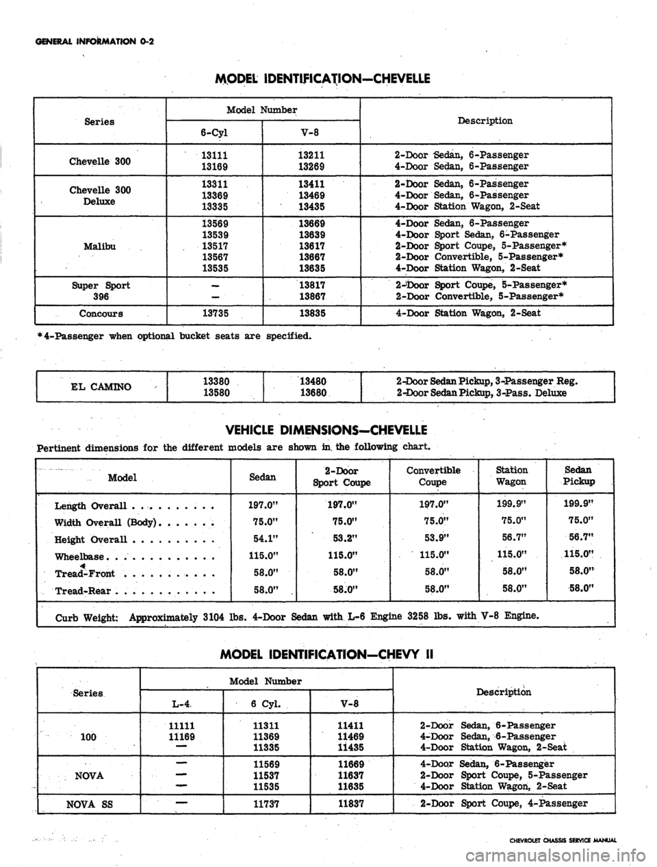
MODEL IDENTIFICATION-CHEVELLE
Series
Chevelle 300
Chevelle 300
Deluxe
Malibu
Super Sport
396
Concours
Model Number
6-Cyl
13111
13169
13311
13369
13335
13569
13539
13517
13567
13535
—
13735
V-8
13211
13269
13411
13469
13435
13669
13639
13617
13667
13635
13817
13867
13835
Description
2-Door -Sedan, 6-Passenger
4-Door Sedan, 6-Passenger
2-Door Sedan, 6-Passenger
4-Door Sedan, 6-Passenger
4-Door Station Wagon, 2-Seat
4-Door Sedan, 6-Passenger
4-Door Sport Sedan, 6-Passenger
2-Door Sport Coupe, 5-Passenger*
2-Door Convertible, 5-Passenger*
4-Door Station Wagon, 2-Seat
2-tooor Sport Coupe, 5-Passenger*
2-Door Convertible, 5-Passenger*
4-Door Station Wagon, 2-Seat
*4-Passenger when optional bucket seats are specified.
EL CAMINO
13380
13580
13480
13680
2-Door
Sedan
Pickup,
3-Passenger Reg.
2-Door
Sedan
Pickup,
3-Pass. Deluxe
VEHICLE DIMENSIONS-CHEVELLE
Pertinent dimensions for the different models are shown in, the following chart.
Model
Sedan
197.0"
75.0"
54.1"
115.0"
58.0"
58.0"
2-Door
Sport Coupe
197.0"
75.0"
53.2"
115.0"
58.0"
58J0"
Convertible
Coupe
197.0"
75.0"
53.9"
115.0"
58.0"
58.0"
Station
Wagon
199.9"
75.0"
56.7"
115.0"
58.0"
58.0"
Sedan
Pickup
199.9"
75.0"
56.7"
115.0"
58.0"
58.0"
Length Overall .
Width Overall (Body)
Height Overall . . .
Wheelbase. .
Tread-Front
Tread-Rear .
Curb Weight: Approximately 3104 lbs. 4-Door Sedan with L-6 Engine 3258 lbs. with V-8 Engine.
MODEL IDENTIFICATION-CHEVY II
Series
100
NOVA
NOVA SS
Model Number
L-4
11111
11169
mmm.
—
6 Cyl.
11311
11369
11335
11569
11537
11535
11737
V-8
11411
11469
11435
11669
11637
11635
11837
Description
2-Door Sedan, 6-Passenger
4-Door Sedan, 6-Passenger
4-Door Station Wagon, 2-Seat
4-Door Sedan, 6-Passenger
2-Door Sport Coupe, 5-Passenger
4-Door Station Wagon, 2-Seat
2-Door Sport Coupe, 4-Passenger
CHEVROLET CHASSIS SERVICE MANUAL
Page 5 of 659
GENERAL INFORMATION 0-3
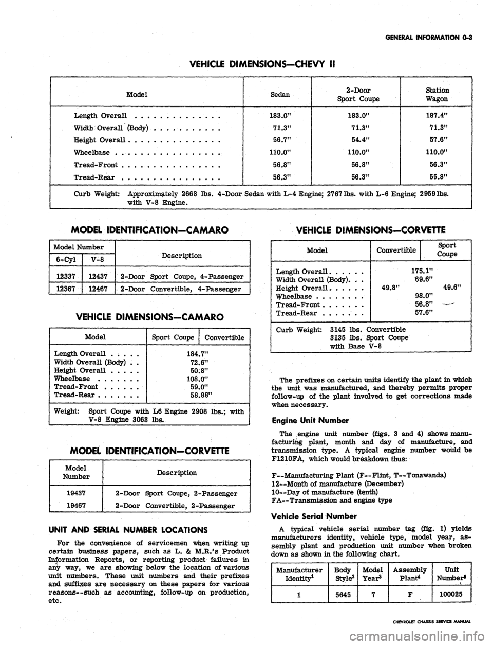
VEHICLE DIMENSIONS-CHEVY II
Model
Length Overall
Width Overall (Body) . . . .
Height Overall
Wheelbase
Tread-Front
Tread-Rear . . .
Sedan
183.0"
71.3"
56.7"
110.0"
56.8"
56.3"
2-Door
Sport Coupe
183.0"
71.3"
54.4"
110.0"
56.8"
56.3"
Station
Wagon
187.4"
71.3"
57.6"
110.0"
56.3"
55.8"
Curb Weight: Approximately 2668 lbs. 4-Door Sedan with L-4 Engine; 2767
lbs.
with L-6 Engine; 2959lbs.
with V-8 Engine.
MODEL IDENTIFICATION-CAMARO
VEHICLE DIMENSIONS-CORVEnE
Model Number
6-Cyl
12337
12367
V-8
12437
12467
Description
2-Door Sport Coupe, 4-Passenger
2-Door Convertible, 4-Passenger
VEHICLE DIMENSIONS-CAMARO
Model
Length Overall .....
Width Overall (Body) . .
Height Overall
Wheelbase
Tread-Front
Tread-Rear
Sport Coupe
Convertible
184.7"
72.6"
50:8"
108.0"
59.0"
58.88"
Weight: Sport Coupe with L6 Engine 2908 lbs.; with
V-8 Engine 3063 lbs.
MODEL IDENTIFICATION-CORVETTE
Model
Number
19437
19467
Description
2-Door Sport Coupe, 2-Passenger
2-Door Convertible, 2-Passenger
UNIT AND SERIAL NUMBER LOCATIONS
For the convenience of servicemen when writing up
certain business papers, such as L. & M.R.'s Product
Information Reports, or reporting product failures in
any way, we are showing below the location of various
unit numbers. These unit numbers and their prefixes
and suffixes are necessary on these papers for various
reasons—such as accounting, follow-up on production,
etc.
Model
Length Overall
Width Overall (Body). . .
Height Overall.
Wheelbase
Tread-Front
Tread-Rear .
Convertible
Sport
Coupe
175.1"
69.6"
49.8"
49.6"
98.0"
56.8"
57.6"
Curb Weight: 3145 lbs. Convertible
3135 lbs. Sport Coupe
with Base V-8
The prefixes on certain units identify the plant in which
the unit was manufactured, and thereby permits proper
follow-up of the plant involved to get corrections made
when necessary.
Engine Unit Number
The engine unit number (figs. 3 and 4) shows manu-
facturing plant, month and day of manufacture, and
transmission type. A typical engine number would be
F1210FA, which would breakdown thus:
F~Manufacturing Plant (F—Flint, T—Tonawanda)
12—Month of manufacture (December)
10—Day of manufacture (tenth)
FA—Transmission and engine type
Vehicle Serial Number
A typical vehicle serial number tag (fig. 1) yields
manufacturers identity, vehicle type, model year, as-
sembly plant and production unit number when broken
down as shown in the following chart.
Manufacturer
Identity1
1
Body
Style2
5645
Model
Year8
7
Assembly
Plant*
F
Unit
Number5
100025
CHEVROLET CHASSIS SERVICE /MANUAL
Page 16 of 659
LUBRICATION 0-14
SAE 5W-30 oils may be used during periods when
temperatures of 32° and below are to be expected.
Types of Oils
In service, crankcase oils may form sludge and varnish
and under some conditions, corrosive acids unless pro-
tected against oxidation.
To minimize the formation of these harmful products
and to assure the use of oil best suited for present day
operating conditions, automobile manufacturers have de-
veloped a series of sequence tests designed to evaluate
the ability of any oil to properly lubricate automobile
engines.
It is recommended that only those oils which are
certified by their suppliers as meeting or exceeding the
maximum severity requirements of these sequence tests
(or GM Standard 4745-M) be used in Chevrolet engines.
Certified sequence tested oils will be described as such
on their containers.
Maintaining Oil Level
The oil gauge rod is marked "Full" and "Add Oil."
These notations have broad arrows pointing to the level
lines.
The oil level should be maintained between the
two lines, neither going above the "Full" line nor under
the "Add Oil" line. DO NOT OVERFILL. After operating
vehicle allow a few minutes for oil to return to crankcase
before checking oil level.
Check the oil level frequently and add oil when
necessary.
Oil and Filter Change Intervals
NOTE:
Under prolonged dusty driving condi-
tions,
it is recommended that these operations
be performed more often.
OIL
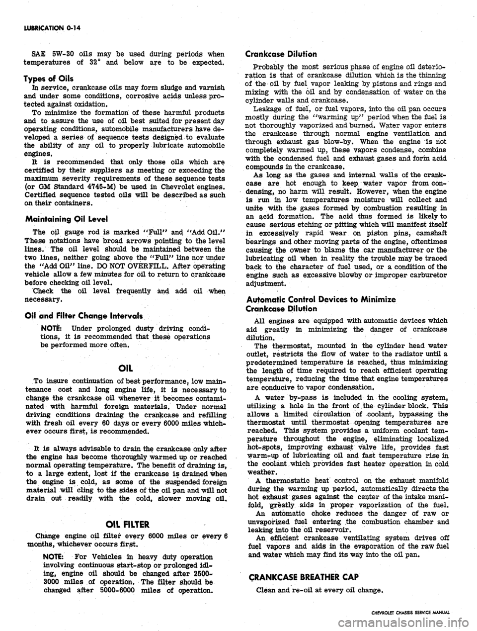
To insure continuation of best performance, low main-
tenance cost and long engine life, it is necessary to
change the crankcase oil whenever it becomes contami-
nated with harmful foreign materials. Under normal
driving conditions draining the crankcase and refilling
with fresh oil every 60 days or every 6000 miles which-
ever occurs first, is recommended.
It is always advisable to drain the crankcase only after
the engine has become thoroughly warmed up or reached
normal operating temperature. The benefit of draining is,
to a large extent, lost if the crankcase is drained when
the engine is cold, as some of the suspended foreign
material will cling to the sides of the oil pan and will not
drain out readily with the cold, slower moving oil.
OIL FILTER
Change engine oil filter every 6000 miles or every 6
months, whichever occurs first.
NOTE:
For Vehicles in heavy duty operation
involving continuous start-stop or prolonged idl-
ing, engine oil should be changed after 2500-
3000 miles of operation. The filter should be
changed after 5000-6000 miles of operation.
Crankcase Dilution
Probably the most serious phase of engine oil deterio-
ration is that of crankcase dilution which is the thinning
of the oil by fuel vapor leaking by pistons and rings and
mixing with the oil and by condensation of water on the
cylinder walls and crankcase.
Leakage of fuel, or fuel vapors, into the oil pan occurs
mostly during the "warming up" period when the fuel is
not thoroughly vaporized and burned. Water vapor enters
the crankcase through normal engine ventilation and
through exhaust gas blow-by. When the engine is not
completely warmed up, these vapors condense, combine
with the condensed fuel and exhaust gases and form acid
compounds in the crankcase.
As long as the gases and internal walls of the crank-
case are hot enough to keep water vapor from con-
densing, no harm will result. However, when the engine
is run in low temperatures moisture will collect and
unite with the gases formed by combustion resulting in
an acid formation. The acid thus formed is likely to
cause serious etching or pitting which will manifest itself
in excessively rapid wear on piston pins, camshaft
bearings and other moving parts of the engine, oftentimes
causing the owner to blame the car manufacturer or the
lubricating oil when in reality the trouble may be traced
back to the character of fuel used, or a condition of the
engine such as excessive blowby or improper carburetor
adjustment.
Automatic Control Devices to Minimize
Crankcase Dilution
All engines are equipped with automatic devices which
aid greatly in minimizing the danger of crankcase
dUution.
The thermostat, mounted in the cylinder head water
outlet, restricts the flow of water to the radiator until a
predetermined temperature is reached, thus minimizing
the length of time required to reach efficient operating
temperature, reducing the time that engine temperatures
are conducive to vapor condensation.
A water by-pass is included in the cooling system,
utilizing a hole in the front of, the cylinder block. This
allows a limited circulation of coolant, bypassing the
thermostat until thermostat opening temperatures are
reached. This system provides a uniform coolant tem-
perature throughout the engine, eliminating localized
hot-spots, improving exhaust valve life, provides fast
warmrup of lubricating oil and fast temperature rise in
the coolant which provides fast heater operation in cold
weather.
A thermostatic heat control on the exhaust manifold
during the warming up period, automatically directs the
hot exhaust gases against the center of the intake mani-
fold, greatly aids in proper vaporization of the fuel.
An automatic choke reduces the danger of raw or
unvaporized fuel entering the combustion chamber and
leaking into the oil reservoir.
An.
efficient crankcase ventilating system drives off
fuel vapors and aids in the evaporation of the raw fuel
and water which may find its way into the oil pan.
CRANKCASE BREATHER CAP
Clean and re-oil at every oil change..
CHEVROLET CHASSIS SERVICE MANUAL
Page 56 of 659
HEATER AND AIR CONDITIONING 1A-33
within the system. The following fixed conditions must be
adhered to in order to make it possible to compare the
performance of the system being tested with the stan-
dards below:
1.
Doors and windows closed. (Car inside or in shade.)
2.
Hood up and engine exhaust suitably ventilated.
3.
Vehicle in NEUTRAL with engine running at 2000
rpm.
4.
Air Conditioning controls set for -
• Maximum cooling.
• High blower speed.
5.
TEMP knob and AIR knob set for full recirculating
air. On Comfortron systems* move the control lever
to REAR and pull the white vacuum hose from the
transducer. Plug the hose. An alternate method is to
install the J-22368 Tester (described later in this
section) and operate it on MANUAL control to main-
tain maximum cooling and blower speed.
6. Gauge set installed.
7.
System settled out (run-in approximately
10
minutes).
8. A thermometer placed in front of vehicle grille and
another in the right hand diffuser outlet.
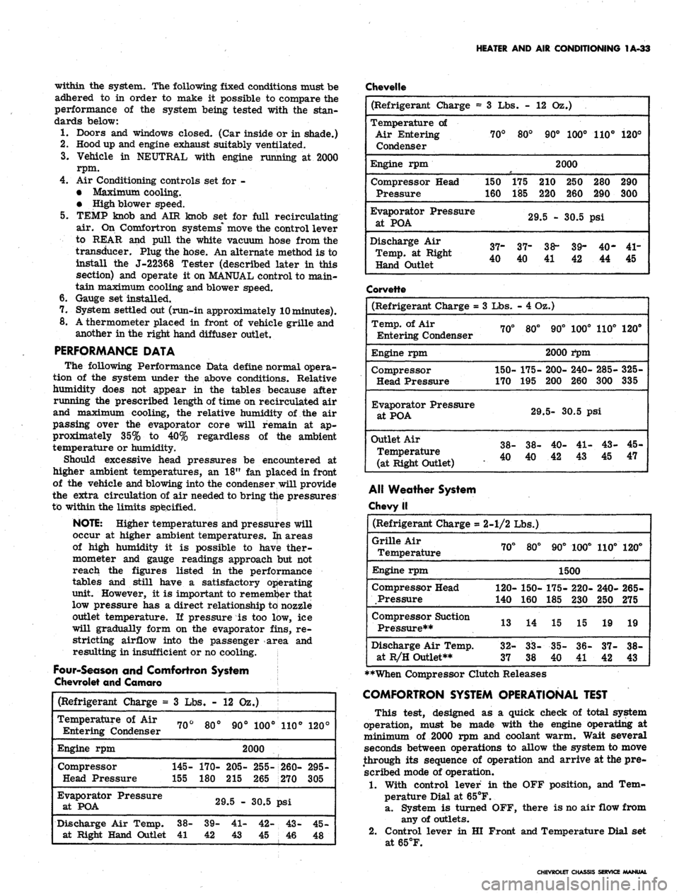
PERFORMANCE DATA
The following Performance Data define normal opera-
tion of the system under the above conditions. Relative
humidity does not appear in the tables because after
running the prescribed length of time on recirculated air
and maximum cooling, the relative humidity of the air
passing over the evaporator core will remain at ap-
proximately 35% to 40% regardless of the ambient
temperature or humidity.
Should excessive head pressures be encountered at
higher ambient temperatures, an 18" fan placed in front
of the vehicle and blowing into the condenser will provide
the extra circulation of air needed to bring the pressures
to within the limits specified.
NOTE: Higher temperatures and pressures will
occur at higher ambient temperatures, fti areas
of high humidity it is possible to have ther-
mometer and gauge readings approach but not
reach the figures listed in the performance
tables and still have a satisfactory operating
unit. However, it is important to remember that
low pressure has a direct relationship to nozzle
outlet temperature. If pressure is too low, ice
will gradually form on the evaporator fins, re-
stricting airflow into the passenger area and
resulting in insufficient or no cooling.
Four-Season and Comfortron System
Chevrolet and Camaro
Chevelle
(Refrigerant
Charge
=
Temperature
of Air
Entering Condenser
Engine rpm
Compressor
Head Pressure
Evaporator Pressure
at POA
Discharge Air Temp,
at Right Hand Outlet
3
Lbs. -
70°
145-
155
38-
41
80°
170-
180
12 02
90°
.)
100°
2000
205-
215
29.5 -
39-
42
41-
43
255-
265
30.5
42-
45
110°
260-
270
psi
43-
46
120°
295-
305
45-
48
(Refrigerant Charge =
Temperature of
Air Entering
Condenser
Engine rpm
Compressor Head
Pressure
Evaporator
Pressure
at
POA
Discharge Air
Temp, at Right
Hand Outlet
3 Lbs. -
70°
150
160
37-
40
80°
175
185
12 Oz.)
90° 100°
2000
210 250
220 260
29.5 - 30.5
37-
40
38-
39-
41 42
110°
280
290
psi
40-
44
120°
290
300
41-
45
Corvette
(Refrigerant Charge =
Temp, of Air
Entering Condenser
Engine rpm
Compressor
Head Pressure
Evaporator
Pressure
at
POA
Outlet
Air
Temperature
(at Right
Outlet)
3
Lbs.
70°
150-
170
38-
40
- 4 Oz.)
80°
175-
195
29
38-
40
90°
2000
200-
200
100°
i*pm
240-
260
110°
285-
300
5-
30.5 psi
40-
42
41-
43
43-
45
120°
325-
335
45-
47
Alt Weather System
Chevy II
(Refrigerant
Charge
=
Grille Air
Temperature
Engine rpm
Compressor Head
Pressure
Compressor Suction
Pressure**
Discharge Air Temp,
at R/H Outlet**
2-1/2 Lbs.)
70°
120-
140
13
32-
37
80°
150-
160
14
CO
OO
CO
CO
90°
100°
1500
175-
185
15
35-
40
220-
230
15
36-
41
110°
240-
250
19
37-
42
120°
265-
275
19
38-
43
**When Compressor Clutch Releases
COMFORTRON SYSTEM OPERATIONAL TEST
This test, designed as a quick check of total system
operation, must be made with the engine operating at
minimum of 2000 rpm and coolant warm. Wait several
seconds between operations to allow the system to move
through its sequence of operation and arrive at the pre-
scribed mode of operation.
1.
With control lever in the OFF position, and Tem-
perature Dial at 65°F.
a. System is turned OFF, there is no air flow from
any of outlets.
2.
Control lever in HI Front and Temperature Dial set
at65°F.
CHEVROLET CHASSIS SERVICE MANUAL
Page 64 of 659
HEATER
AND AIR
CONDITIONING
1A-41
OUTLET
1
TO EXPANSION
^
VALVE
TO
OIL
BLEED LINE
^ INLET
Fig.
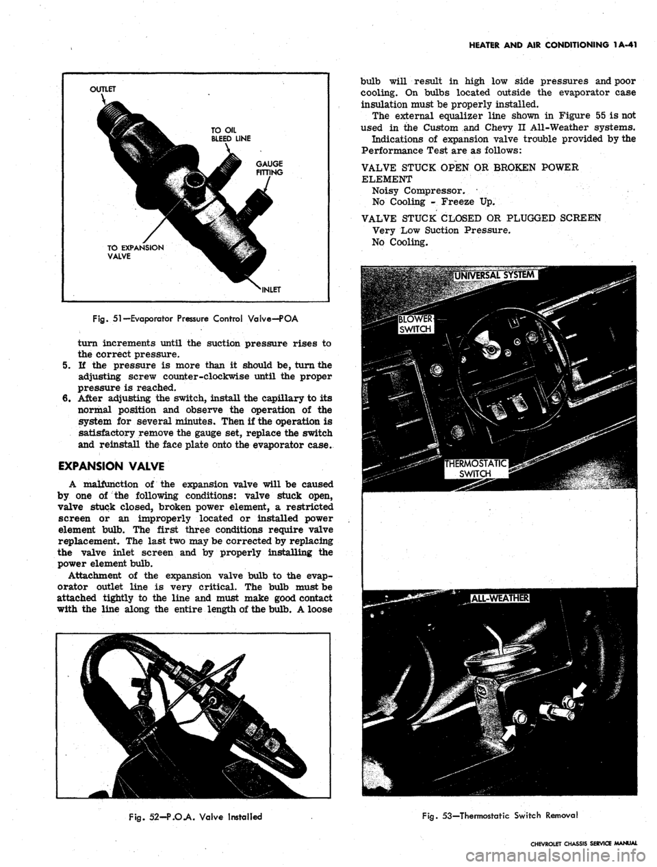
51—Evaporator Pressure Control Valve—POA
turn increments until
the
suction pressure rises
to
the correct pressure.
5.
If the
pressure
is
more than
it
should
be,
turn the
adjusting screw counter-clockwise until
the
proper
pressure
is
reached.
6. After adjusting
the
switch, install the capillary to
its
normal position
and
observe
the
operation
of the
system
for
several minutes. Then
if
the operation
is
satisfactory remove the gauge
set,
replace the switch
and reinstall the face plate onto the evaporator case.
EXPANSION VALVE
A malfunction
of the
expansion valve will
be
caused
by
one of the
following conditions: valve stuck open,
valve stuck closed, broken power element,
a
restricted
screen
or an
improperly located
or
installed power
element bulb.
The
first three conditions require valve
replacement.
The
last two may be corrected by replacing
the valve inlet screen
and by
properly installing
the
power element bulb.
Attachment
of the
expansion valve bulb
to the
evap-
orator outlet line
is
very critical.
The
bulb must be
attached tightly
to the
line
and
must make good contact
with
the
line along
the
entire length
of
the bulb. A loose
bulb will result
in
high
low
side pressures and poor
cooling.
On
bulbs located outside
the
evaporator case
insulation must be properly installed.
The external equalizer line shown
in
Figure
55 is
not
used
in the
Custom
and
Chevy
II
All-Weather systems.
Indications
of
expansion valve trouble provided by the
Performance Test are
as
follows:
VALVE STUCK OPEN
OR
BROKEN POWER
ELEMENT
Noisy Compressor.
•
No Cooling
-
Freeze
Up.
VALVE STUCK CLOSED
OR
PLUGGED SCREEN
Very Low Suction Pressure.
No Cooling.
Fig.
52-P.O.A. Valve Installed
Fig.
53—Thermostatic Switch Removal
CHEVROLET CHASSIS SERVICE MANUAL
Page 69 of 659
HEATER AND AIR CONDITIONING 1A-46
MAKE ANGULAR CUT
FOR HOSE REMOVAL
LOCATING
BEAD
SEALING
BEADS
LOCATING
BEAD
not to nick or score the sealing beads when
cutting off the hose. Cutting the hose lengthwise
may result in this problem.
Fig.
58—Hose Clamp Connections
NOTE:
Where steel to aluminum connections
are being made, use torque for aluminum tubing.
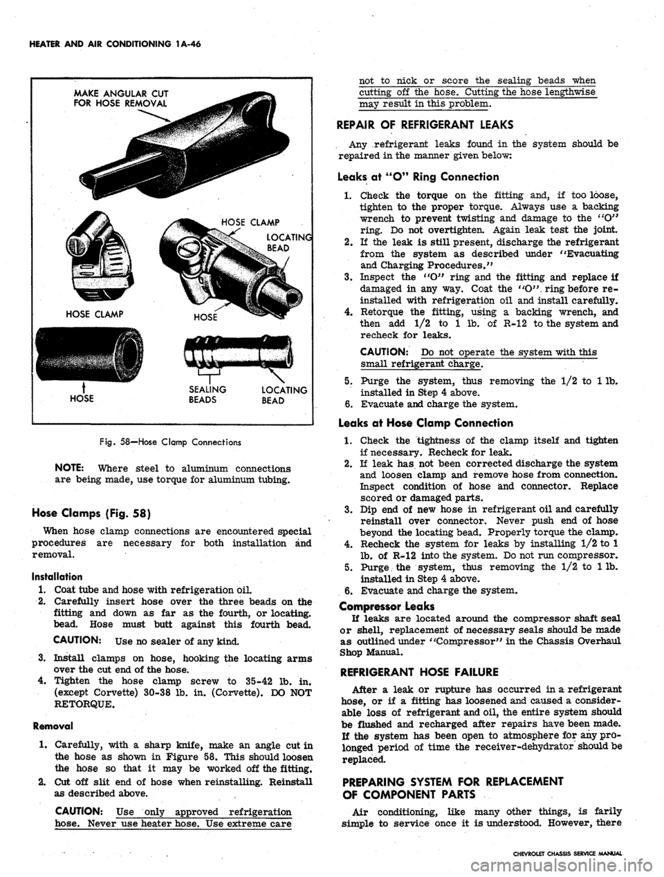
Hose Clamps (Fig. 58)
When hose clamp connections are encountered special
procedures are necessary for both installation and
removal.
Installation
1.
Coat tube and hose with refrigeration oil.
2.
Carefully insert hose over the three beads on the
fitting and down as far as the fourth, or locating,
bead. Hose must butt against this fourth bead.
CAUTION: Use no sealer of any kind.
3.
Install clamps on hose, hooking the locating arms
over the cut end of the hose.
4.
Tighten the hose clamp screw to 35-42 lb. in.
(except Corvette) 30-38 lb. in. (Corvette). DO NOT
RETORQUE.
Removal
1.
Carefully, with a sharp knife, make an angle cut in
the hose as shown in Figure 58. This should loosen
the hose so that it may be worked off the fitting.
2.
Cut off slit end of hose when reinstalling. Reinstall
as described above.
CAUTION: Use only approved refrigeration
hose. Never use heater hose. Use extreme care
REPAIR OF REFRIGERANT LEAKS
Any refrigerant leaks found in the system should be
repaired in the manner given below:
Leaks at "O" Ring Connection
1.
Check the torque on the fitting and, if too loose,
tighten to the proper torque. Always use a backing
wrench to prevent twisting and damage to the "O"
ring. Do not overtighten. Again leak test the joint.
2.
If the leak is still present, discharge the refrigerant
from the system as described under "Evacuating
and Charging Procedures."
3.
Inspect the ''O" ring and the fitting and replace if
damaged in any way. Coat the "O". ring before re-
installed with refrigerati6n oil and install carefully.
4.
Retorque the fitting, using a backing wrench, and
then add 1/2 to 1 lb. of R-12 to the system and
recheck for leaks.
CAUTION: Do not operate the system with this
small refrigerant charge.
5. Purge the system, thus removing the 1/2 to 1 lb.
installed in Step 4 above.
6. Evacuate and charge the system.
Leaks at Hose Clamp Connection
1.
Check the tightness of the clamp itself and tighten
if necessary. Recheck for leak.
2.
If leak has not been corrected discharge the system
and loosen clamp and remove hose from connection.
Inspect condition of hose and connector. Replace
scored or damaged parts.
3.
Dip end of new hose in refrigerant oil and carefully
reinstall over connector. Never push end of hose
beyond the locating bead. Properly torque the clamp.
4.
Recheck the system for leaks by installing 1/2 to 1
lb.
of R-12 into the system. Do not run compressor.
5. Purge. the system, thus removing the 1/2 to 1 lb.
installed in Step 4 above.
6. Evacuate and charge the system.
Compressor Leaks
If leaks are located around the compressor shaft seal
or shell, replacement of necessary seals should be made
as outlined under "Compressor" in the Chassis Overhaul
Shop Manual.
REFRIGERANT HOSE FAILURE
After a leak or rupture has occurred in a refrigerant
hose, or if a fitting has loosened and caused a consider-
able loss of refrigerant and oil, the entire system should
be flushed and recharged after repairs have been made.
Ji the system has been open to atmosphere for any pro-
longed period of time the receiver-dehydrator should be
replaced.
PREPARING SYSTEM FOR REPLACEMENT
OF COMPONENT PARTS
Air conditioning, like many other things, is farily
simple to service once it is understood. However, there
CHEVROLET CHASSIS SERVICE MANUAL
Page 85 of 659
HEATER AND AIR CONDITIONING 1A-62
2.
Insert the evaporator assembly into the outlet case
half and mount the evaporator, thermostatic switch,
and cable to the case.
3.
Install the face plate to the case and install control
retaining nuts and knobs.
4.
Assemble the case halves and mount the evaporator
pipe clamp.
5. Install the evaporator assembly as previously
described under EVAPORATOR.
BLOWER ASSEMBLY
Four-Season System
Chevrolet and Camaro
Removal
1.
Disconnect battery ground cable.
2.
Remove the right front fender and skirt assembly.
3.
Disconnect the motor wire at the flange connector.
4.
Disconnect the rubber air cooling tube from the
motor.
5. Remove the motor to case attaching screws and re-
move the blower assembly. If the sealer acts as an
adhesive, pry the assembly carefully away from the
6. Remove the blower from the motor shaft.
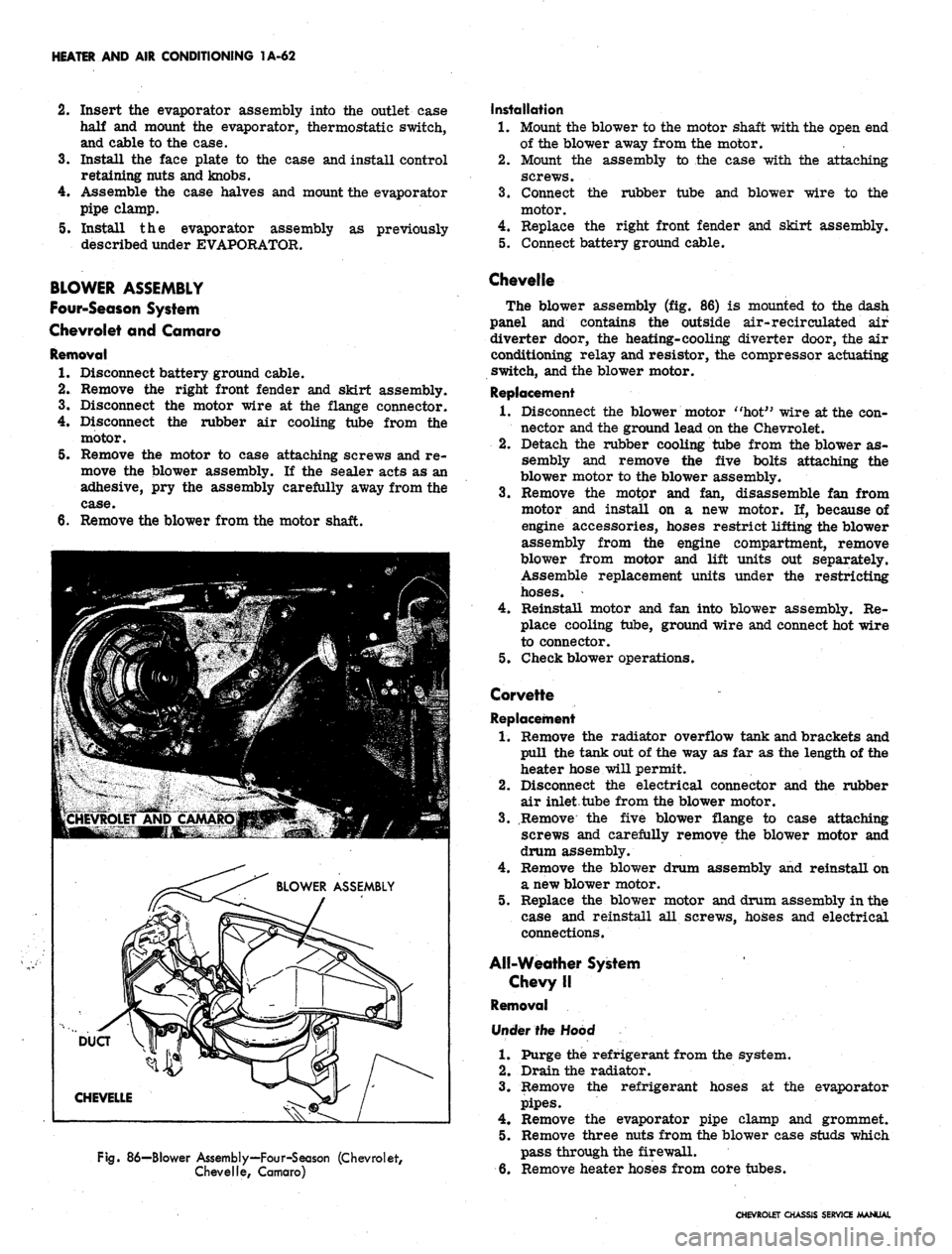
Fig.
86—Blower Assembly—Four-Season (Chevrolet,
Chevelle, Camaro)
Installation
1.
Mount the blower to the motor shaft with the open end
of the blower away from the motor.
2.
Mount the assembly to the case with the attaching
screws.
3.
Connect the rubber tube and blower wire to the
motor.
4.
Replace the right front fender and skirt assembly.
5. Connect battery ground cable.
Chevelle
The blower assembly (fig. 86) is mounted to the dash
panel and contains the outside air-recirculated air
diverter door, the heating-cooling diverter door, the air
conditioning relay and resistor, the compressor actuating
switch, and the blower motor.
Replacement
1.
Disconnect the blower motor "hot" wire at the con-
nector and the ground lead on the Chevrolet.
2.
Detach the rubber cooling tube from the blower as-
sembly and remove the five bolts attaching the
blower motor to the blower assembly.
3.
Remove the motor and fan, disassemble fan from
motor and install on a new motor. If, because of
engine accessories, hoses restrict lifting the blower
assembly from the engine compartment, remove
blower from motor and lift units out separately.
Assemble replacement units under the restricting
hoses.
4.
Reinstall motor and fan into blower assembly. Re-
place cooling tube, ground wire and connect hot wire
to connector.
5. Check blower operations.
Corvette
Replacement
1.
Remove the radiator overflow tank and brackets and
pull the tank out of the way as far as the length of the
heater hose will permit.
2.
Disconnect the electrical connector and the rubber
air inlet tube from the blower motor.
3.
Remove the five blower flange to case attaching
screws and carefully remove the blower motor and
drum assembly.
4.
Remove the blower drum assembly and reinstall on
a new blower motor.
5. Replace the blower motor and drum assembly in the
case and reinstall all screws, hoses and electrical
connections.
All-Weather System
Chevy II
Removal
Under the Hood
1.
Purge the refrigerant from the system.
2.
Drain the radiator.
3.
Remove the refrigerant hoses at the evaporator
pipes.
4.
Remove the evaporator pipe clamp and grommet.
5. Remove three nuts from the blower case studs which
pass through the firewall.
6. Remove heater hoses from core tubes.
CHEVROLET CHASSIS SERVICE MANUAL
Page 93 of 659
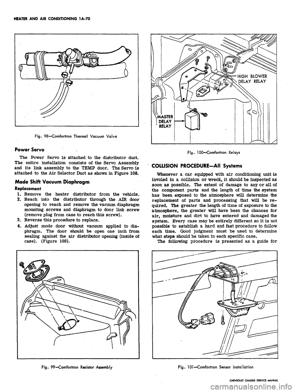
HEATER AND AIR CONDITIONING 1A-70
Fig.
98—Comfortron Thermal Vacuum Valve
Power Servo .
The Power Servo is attached, to the distributor duct.
The entire installation consists of the Servo Assembly
and its link assembly to the TEMP door. The Servo is
attached to the Air Selector Duct as shown in Figure 108.
Mode Shift Vacuum Diaphragm
Replacement
1.
Remove the heater distributor from the vehicle.
2.
Reach into the distributor through the AIR door
opening to reach and remove the vacuum diaphragm
mounting screws and diaphragm to door link screw
(remove piug from case to reach this screw).
3.
Reverse this procedure to replace.
4.
Adjust mode door without vacuum applied to dia-
phragm. The door should be open one inch from
sealing against the air distributor opening (inside of
case).
(Figure 109).
HIGH BLOWER
DELAY RELAY
.MASTER
DELAY
RELAY
Fig.
100—Comfortron Relays
COLLISION PROCEDURE-AII Systems
Whenever a car equipped with air conditioning unit is
involed in a collision or wreck, it should be inspected as
soon as possible. The extent of damage to any or all of
the component parts and the length of time the system
has been exposed to the atmosphere will determine the
replacement of parts and processing that will be re-
quired. The greater the length of time of exposure to the
atmosphere, the greater will have been the chances for
air, moisture and dirt to have entered and damaged the
system. Every case may be entirely different so it is not
possible to establish a hard and fast procedure to follow
each time. Good judgment must be used to determine
what steps should be taken in each specific case.
The following procedure is presented as a guide for
Fig.
99—Comfortron Resistor Assembly
Fig.
101—Comfortron Sensor Installation
CHEVROLET CHASSIS SERVICE MANUAL
Page 94 of 659
HEATER AND AIR CONDITIONING 1A-71
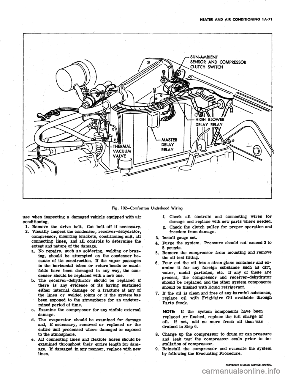
SUN-AMBIENT
SENSOR AND COMPRESSOR
CLUTCH SWITCH
HIGH BLOWER
DELAY RELAY
THERMAL
VACUUM
VALVE
Fig.
102-Comfortron Underhood Wiring
use when inspecting a damaged vehicle equipped with air
conditioning.
1.
Remove the drive belt. Cut belt off if necessary.
2.
Visually inspect the condenser, receiver-dehydrator,
compressor, mounting brackets, conditioning unit, all
connecting lines, and all controls to determine the
extent and nature of the damage.
a. No repairs, such as soldering, welding or braz-
ing, should be attempted on the condenser be-
cause of its construction. If the vapor passages
in the horizontal tubes or return bends or mani-
folds have been damaged in any way, the con-
denser should be replaced with a new one.
b.
The receiver-dehydrator should be replaced if
there is any evidence of its having sustained
either internal damage or a fracture at any of
the lines or welded joints or if the system has
been exposed to the atmosphere for an undeter-
mined period of time.
c. Examine the compressor for any visible external
damage.
d. The evaporator should be examined for damage
and, if necessary, removed or replaced or the
entire unit processed where damaged or exposed
to the atmosphere.
e. All connecting lines and flexible hoses should be
examined throughout their entire length for dam-
age.
If damaged in any manner, replace with new
lines.
f. Check all controls and connecting wires for
damage and replace with new parts where needed.
g. Check the clutch pulley for proper operation and
freedom from damage.
3.
Install gauge set.
4.
Purge the system. Pressure should not exceed 3 to
5 pounds.
5. Remove the compressor from mounting and remove
the oil test fitting.
6. Pour out the oil into a clean glass container and ex-
amine it for any foreign substance such as dirt,
water, metal particles, etc. If any of these are
present, the compressor and receiver-dehydrator
should be replaced and the other system components
should be flushed with liquid refrigerant.
7. If the oil is clean and free of any harmful substance,
replace oil with Frigidaire Oil available through
Parts Stock.
NOTE:
If the system components have been
replaced or flushed, replace the full charge of
oil. If not, add no more fresh oil than was
drained in Step 6.
8. Charge up the compressor to drum or can pressure
and leak test the compressor seals prior to in-
stallation of compressor.
9. Reinstall the compressor and evacuate the system
by following the Evacuating Procedure.
CHEVROLET CHASSIS SERVICE MANUAL