check engine CHEVROLET CAMARO 1971 2.G User Guide
[x] Cancel search | Manufacturer: CHEVROLET, Model Year: 1971, Model line: CAMARO, Model: CHEVROLET CAMARO 1971 2.GPages: 88, PDF Size: 34.8 MB
Page 38 of 88
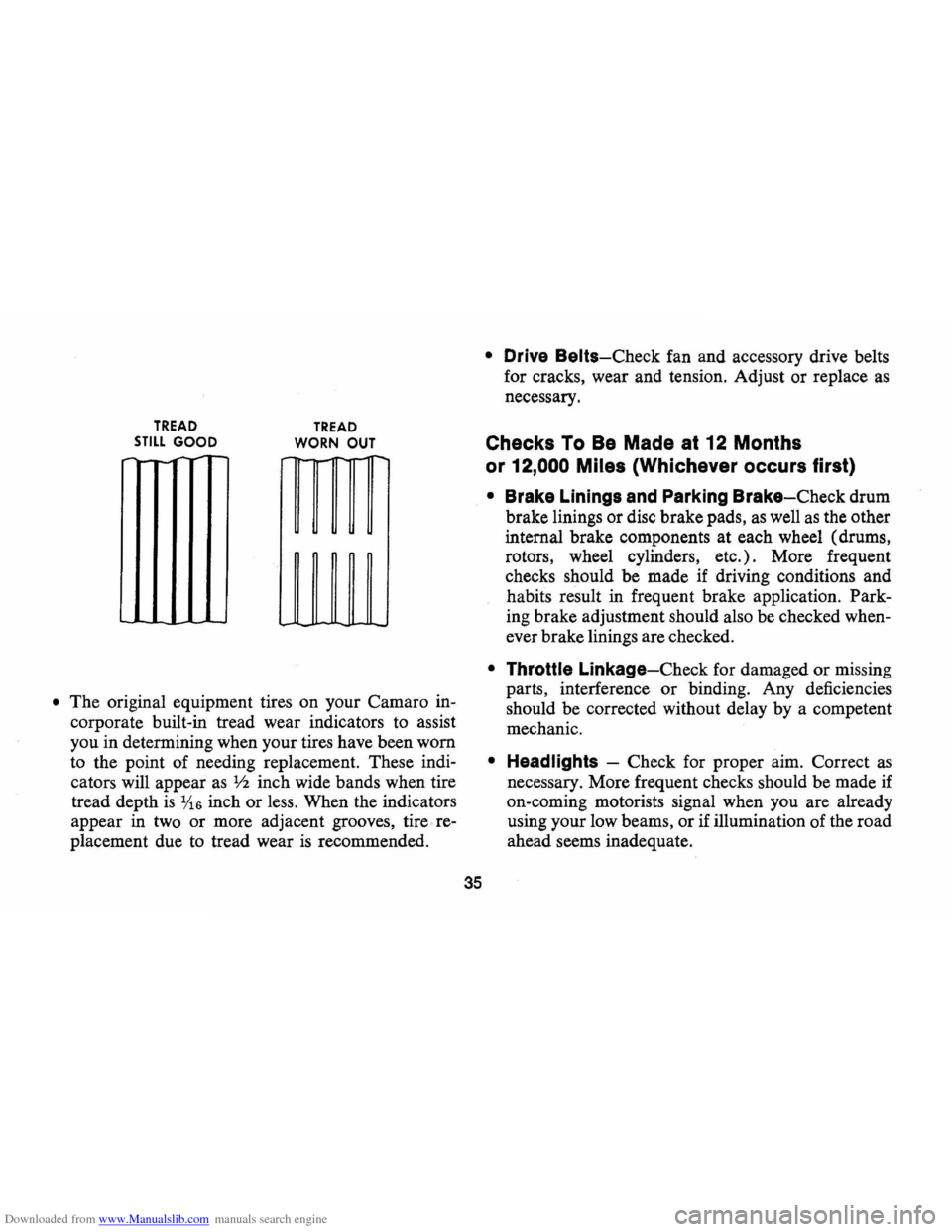
Downloaded from www.Manualslib.com manuals search engine TREAD STILL GOOD
-
TREAD
WORN OUT
• The original equipment tires on your Camaro in
corporate built-in tread wear indicators to assist
you in detennining when your tires have been worn
to the point of needing replacement. These indi
cators will appear
as V2 inch wide bands when tire
tread depth
is 1;16 inch or less. When the indicators
appear in two or more adjacent grooves, tire re
placement due to tread wear
is recommended.
35
• Drive Belts-Check fan and accessory drive belts
for cracks, wear and tension. Adjust or replace
as
necessary.
Checks To Be Made at 12 Months
or
12,000 Miles (Whichever occurs first)
• Brake Linings and Parking Brake-Check drum
brake linings or disc brake pads,
as well as the other
internal brake components at each wheel (drums,
rotors, wheel cylinders, etc.) . More frequent
checks should be made if driving conditions and
habits result in frequent brake application. Park
ing brake adjustment should also be checked when
ever brake linings are checked.
• Throttle Linkage-Check for damaged or missing
parts, interference or binding. Any deficiencies
should be corrected without delay by a competent
mechanic.
• Headlights -Check for proper aim. Correct as
necessary. More frequent checks should be made if
on-coming motorists signal when you are already
using your low beams, or if illumination of the road
ahead seems inadequate.
Page 39 of 88
Downloaded from www.Manualslib.com manuals search engine For further details on the engine and transmission
items listed on the
"Vehicle Safety Maintenance
Schedule," and for other recommended maintenance,
refer
to the "Service and Maintenance" and "Air
Pollution. Control" Sections of this manual.
CHECKS lOBE PERFORMED
BY OWNER
Listed below are the safety checks that should be
made by the owner . These checks should be made at
least every 4 months or
6,000 miles, whichever occurs
first , or more often when so indicated . Any
deficien
cies should be brought to the attention of your dealer
or service station, so the advice of a qualified mech
anic is available regarding the need for repairs or
replacements.
• Anti-Theft Lock-Check for proper operation by
attempting to turn key to
LOCK position in the
various transmission gears with
car stationary. Key
should
tum to LOCK position only when trans
mission control is in PARK on automatic trans
mission models or in REVERSE on manual trans
mission models.
• Seat Belts-Check lap and shoulder belts as well
as buckles, retractors and anchors for loose con-
36
nections, damage and positive latching action.
• Windshield Wipers and Washers-Check con
dition and alignment of wiper blades. Check
amount and direction of fluid sprayed by washers
during use.
• Defrosters-Check performance by turning con
trols to "de-ice" and "Hi" fan speed and noting
amount of air directed against the windshield.
• Wheel Alignment and Balance-In addition to
abnormal tire wear the need for wheel alignment
service may be indicated by a pull to the right or
left when driving on a straight level road. The need
for wheel balancing may be indicated by a
vibra
tion at the steering wheel while driving.
• Parking Brake and "Park" Mechanism-Check
parking brake holding ability by parking on a fairly
steep hill and restraining the vehicle with the
parking brake only.
On cars with automatic trans
missions, check the holding ability of the "Park"
mechanism by releasing all brakes after the trans
mission selector lever has been placed in the "P"
position.
• Lights -Check license plate lights, side marker
lights , headlamps, parking lamps, tail lamps , brake
Page 40 of 88
Downloaded from www.Manualslib.com manuals search engine lights, turn signals, backup lamps, and hazard
warning flashers. Have someone observe operation
of each light while you activate the controls.
• Starter Safety Switch (Automatic Transmis
sion Cars)
CAUTION: Before making the following check, be sure to have a clear distance ahead and behind the car, set the parking brake and firmly apply the foot brake. Do not depress accelerator pedal. Be prepared to turn ott ignition switch immediately if engine should start.
Check starter safety switch by placing the transmis
sion in each of the driving gears while attempting to
start the engine. The starter should operate only in the
Park ("P") or Neutral ("N") positions.
• Starter Interlock (Manual Transmission Cars)
-To check a manual transmission equipped car,
depress the clutch halfway, place the transmission
in neutral, and attempt to start.
The starter should
operate only when clutch
is fully depressed.
• Transmission Shift Indicator-Check to be sure
shift indicator accurately indicates the shift posi
tion selected.
• Horn-Blow the horn occasionally to be sure that
it works.
37
• Seat Back LatcheS-Check to see that seat bac k
latches are holding by pulling forward on the seat
back top.
• Rearview Mirrors and Sun Visors-Check that
friction joints are properly adjusted so mirrors and
sun visors stay in the selected position.
• Door LatcheS-Check for positive closing, la tch
ing and locking.
• Hood Latches-Check to make sure hood closes
firmly . Check also for broken , d amaged or missing
parts which might prevent secure latching.
• Fluid LeakS-Check for fuel, water, oil or other
fluid leaks by observing the ground beneath the
vehicle after it has been parked for a while . (Water
dripping from air conditioning system after use
is
normal). If gasoline fumes are noticed at any time,
the cause should be determined
and corrected with
out delay because of the possibility of fire.
• Exhaust System-See engine exhaust gas caution
at beginning of starting and operating section of
this manual for suggested driver observations and
checks.
Page 42 of 88
Downloaded from www.Manualslib.com manuals search engine • To. start the car when the Ener
gizer (battery)
is discharged,
use a single auxiliary battery
Qr
Energizer Qf the same vQltage as
the discharged battery, with suit
able jumper cables.
• Make cQnnectiQns detailed as
fQllQws:
Jump Starting with
Auxiliary (Booster) Battery
If booster battery is part Qf an
Qther vehicle's electrical system,
bQQster shQuld be treated carefully
when using jumper cables.
FQllQW
exactly the prQcedure Qutlined be
IQw, being careful nQt to. cause
sparks:
1. Set parking brake and place
autQmatic transmissiQn in
"PARK" ("NEUTRAL" fQr
manual transmissiQn).
2. Attach
Qne end of Qne jumper
cable
to. the PQsitive terminal Qf
the booster battery (identified by
"+" or "P" Qn the battery case,
PQst Qr clamp) and the Qther end
Qf same cable to. PQsitive ter
minal
Qf discharged battery.
3. Attach ene end ef the remain
ing cable
to. negative terminal
("-" er "N") ef booster battery,
and finally to. negative terminal
ef discharged battery -taking
i;cAufICsN}R.4btAl0W,CAP '!":;',';"S"!<"" .
···.···.T~·p,.v~ttt.,0 •• ot~~()l.nf.·#rii·j~6Itl t"~
'd.nger of being '. bu'n.d,~oo/.ntl.v.' .houldb.'ch.cked,.ndcoo/.nt .dd.4. only wh.n the .nglne/. cool.
'.Donot r.IJJov.radl.tbic.p whlj."'gln~ .ndradl.to,are.tlll hot, b.c.u ••. the
. cooling sVst.", will blow 'out .c.,dlng , fluid .nd st"m und.r pr.ssur ••
,
tol.mov. b"pWh.riengln./s
39
care that jumper clamps do. nQt
CQntact each ether,
Reverse this sequence exactly
when remeving the jumper cables.
CAUTION: Any proc~ur.~th.rt".n the'
.bove could r •• ult In person.' In/ury c.us.d by electrolyte .qulrtlng out .th. b.tt.ryvent., d.m.g. or In/ury due to b.tt.ry .xplo./on .ndlor d.m.g. to the charging sy.t.m of the boost., v.hlc/,'; or Immoblllz.d . v.hlcl.'. chargIng 'Y'tem. Do not .ttempt to lump .tart a c.r havIng • frozen battery b.cau •• the bit
t.ry mlY .xplod.. It • froz.n b.ttery I. su.pect.d, op.n .nd .x.mln •• 11 fill v.nt. , on the b.ttery. If Ie. c.n b •.. en, or the .,.ctrolyt. fluid c.nnotb •••• n, do not
att.mpt to .tart with /um".r c.bl ...
.'. $Iow~y ,otat • . c.p . count.rC/ockwl'~ .iQ ; d.terit(DO NOT PRESS DOWN WHILE
ROTATING).
•. Walt unt/f.ny ,e.ldu.' pressure I.re' lI.v.d-•• Indlc.t.d by • hissIng .ound.
• p,.ss down on c.p whll. continuing to rot.te counterclockwise.
Radl.tor pre.,ure cap. should b. check.d by • quallfl.d m.chanlc p.rlodlcally for proper op.ratlon and replaced .s r .. qulr.d with the .pplicabl.AC typ •.
Page 43 of 88
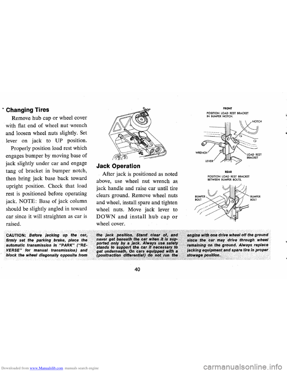
Downloaded from www.Manualslib.com manuals search engine · Changing Tires
Remove hub cap or wheel cover
with fiat end of wheel
nut wrench
and loosen wheel nuts slightly.
Set
lever on jack to UP position.
Properly position load rest which
engages bumper by moving base of
jack slightly under car and engage
tang of bracket in bumper notch,
then bring jack base back toward
upright position. Check that load
rest is positioned before operating
jack.
NOTE: Base of jack column
should be slightly angled in toward
car since it will straighten as car
is
raised.
firmly
automatic rralrlSOIlSSlon
VERSE" lor manual transmission)
Jack Operation
After jack is positioned as noted
above, use wheel nut wrench
as
jack handle and raise car until tire
clears ground. Remove wheel nuts
and wheel, install spare and tighten
wheel nuts. Move jack lever to
DOWN and install hub cap or
wheel cover.
block the wheel diagonally opposite .. _.... .,.. __
40
FRONT POSITION LOAD REST BRACKET IN BUMPER NOTCH.
REAR POSITION LOAD REST BRACKET BETWEEN BUMPER BOLTS.
BUMPER BOlT
Page 47 of 88
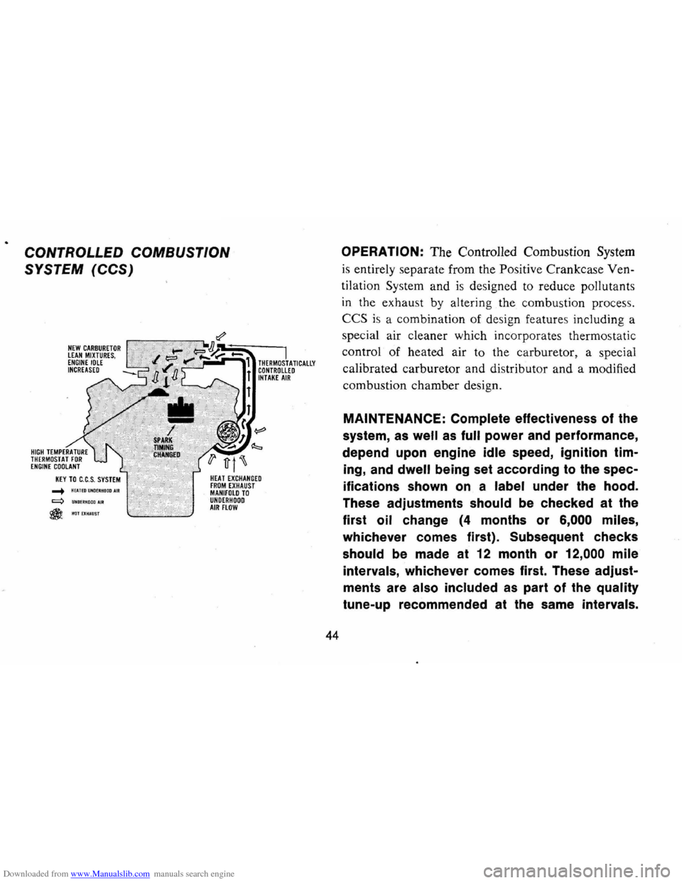
Downloaded from www.Manualslib.com manuals search engine CONTROLLED COMBUSTION
SYSTEM
(CCS)
NEW CARBURETOR LEAN MIXTURES, ENGINE IDLE INCREASED
..... HEAlEDUNDEIiHODDAIR q UND£RHOODAJR
@HOTEXHAUST
I THERMOSTATICALLY CONTROLLED INTAKE AIR
HEAT EXCHANGED FROM EXHAUST MANIFOLD TO UNDERHOOD AIR FLOW
44
OPERATION: The Controlled Combustion System
is entirely separate from the Positive Crankcase Ven
tilation
Sys tem and is designed to reduce pollutants
in the exhau st by altering the combustion process,
CCS is a combination of design features including a
special air cleaner which incorporates thermostatic
control of heated air to the carburetor, a special
calibrated carburetor and distributor and a modified
combustion chamber design,
MAINTENANCE: Complete effectiveness of the
system,
as well as full power and performance,
depend
upon engine idle speed, ignition tim
ing,
and dwell being set according to the spec
ifications
shown on a label under the hood.
These adjustments should be checked at the
first oil change
(4 months or 6,000 miles,
whichever comes first). Subsequent checks
should be made at
12 month or 12,000 mile
intervals, whichever comes first. These adjust
ments are also included
as part of the quality
tune-up recommended at
the same intervals.
Page 48 of 88
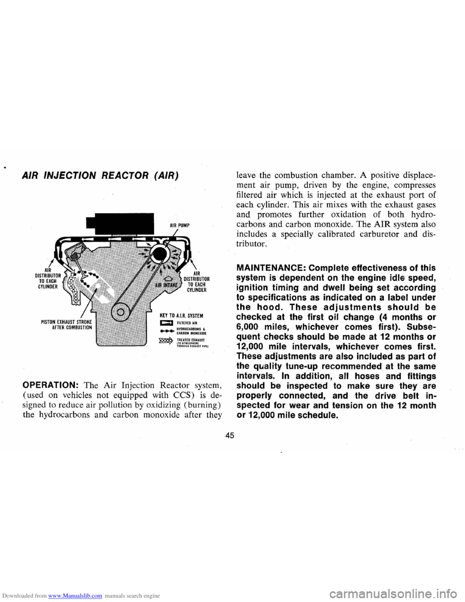
Downloaded from www.Manualslib.com manuals search engine AIR INJECTION REACTOR (AIR)
KEY TO HR. SYSTEM CJ F1LTEREDAIR
.... ~!~:~~A:~~~~I:E ~ TREATED EXHAUST ~(TOUMOS'HERE THMOUGHHHAlIST'II'E)
OPERATION: The Air Injection Reactor system,
(used on vehicles not equipped with
CCS) is de
signed to reduce air pollution by oxidizing (burning)
the hydrocarbons and carbon monoxide after they
45
leave the combustion chamber. A positive displace
ment air pump, driven by the engine, compresses
filtered air which
is injected at the exhaust port of
each cylinder. This air mixes with the exhaust gases
and promotes further oxidation of both hydro
carbons and carbon monoxide. The
AIR system also
includes a specially calibrated carburetor and dis
tributor.
MAINTENANCE: Complete effectiveness of this
system
is dependent on the engine idle speed,
ignition timing and
dwell being set according
to specifications as indicated on a label under
the hood. These adjustments should be
checked at the first oil change (4 months or
6,000 miles, whichever comes first). Subse
quent checks should be made at 12 months or
12,000 mile intervals, whichever comes first.
These adjustments are
also included as part of
the
quality tune-up recommended at the same
intervals. In addition, all hoses and fittings
should be inspected to make sure they are
properly connected, and the drive belt in
spected for wear
and tension on the 12 month
or
12,000 mile schedule.
Page 55 of 88
Downloaded from www.Manualslib.com manuals search engine NOTE: If this cap requires a re
placement, only· a cap with these
same features should be used. Fail
ure to use the correct cap can re
sult in a serious malfunction of the
system. Correct replacement caps
may
be obtained from your Au
thorized Chevrolet Dealer.
Engine Oil
Recommendations
Use only engine oil which meets
oil quality standard GM 6041-M.
High quality oils which are in
tended for service
MS and pass car
makers' tests are
of this quality.
The oil change interval (see para
graph entitled
"Engine Oil Change
Interval") and the new vehicle
warranty are based on the use of
oils that meet these requirements.
NOTE: Non-detergent and other
low quality oils are specifically not
recommended. The use of proper
engine oils and oil change intervals are
your best assurance of contin
ued reliability and performance
from your Camaro engine.
Checking Oil Level
The engine oil should be main
tained at proper level. The best
time to check it
is before operating
the engine or as
the last step in a
fuel stop. This will allow the oil ac
cumulation in the engine to drain
back in the crankcase .
To check
the evel, remove the oil gauge rod
(dip stick), wipe it clean and rein
sert it firmly for an accurate read
ing. The oil gauge rod
is marked
"FULL" and "ADD." The oil level
should be maintained in the safety
margin, neither going above the
"FULL" line nor below the "ADD"
line. Reseat the gauge firmly after
taking the reading.
NOTE: The oil gauge rod is also
marked
"Use GM 6041-M Quality
MS Oil" as a reminder to use only
52
high quality oils as prescribed
under "Engine Oil Recommenda
tions."
Supplemental Engine Oil
Additives
The regular use of supplemental
additives
is specifically not recom
mended and will increase operat
ing costs. However, in cases of spe
cific problems which may arise
under certain conditions, additive
supplements are available that can
effectively and economically solve
these problems without causing
other difficulties.
For example, if
higher detergency
is required to re
duce varnish and sludge deposits
resulting from some unusual opera
tional difficulty, a thoroughly tested
and approved concentrate -
"En
gine Oil Supplement"-is available
at your Chevrolet dealer.
It is sug
gested that, in the event of
an oper
ational problem, you consult your
dealer for advice.
Page 56 of 88
Downloaded from www.Manualslib.com manuals search engine Engine Oil Change Interval
Change oil each 4 months. If
more than 6,000 miles are driven
in a 4-month period, change oil
each
6,000 miles.
In certain types of service in
cluding:
• operation under dusty condi
tions,
• trailer pulling,
• extensive idling, or
• short trip operation at freezing
temperatures (engine not
thor
oughly warmed up),
the oil change interval should not
exceed 2 months, or
3,000 miles,
whichever occurs
first. Operation
in dust storms may require an im
mediate change of oil. See your
Chevrolet dealer for advice on the
frequency of oil and filter changes under
unusual driving conditions.
The above recommendations
apply to the first change
as well as
subsequent oil changes. The oil
change interval for your Camaro
engine
is based on the use of oils
that
meet. the requirements indi
cated in the section on "Engine Oil
Recommendations." Oil change in
tervals longer than those listed
above will result in serious
reduc
tion in engine life and may affect
Chevrolet's obligation under the
provisions of the
New Vehicle War
ranty.
A high quality
MS oil meeting
General Motors Standard GM
6041-M was installed in your en
gine at the factory. It is not neces
sary to change this factory-installed
oil prior to the recommended
nor
mal change period. However, the
oil level should
be checked more
frequently during the break-in pe
riod since somewhat higher oil con-
53
sumption is normal until the piston
rings become seated.
Manifold Heat
Control Valve
Every 6,000 miles or 4 months,
check heat control valve for free
dom of operation.
If shaft is stick
ing free it up with GM Manifold
Heat Control Solvent or its equiva
lent.
Engine
Oil Filter
Replacement
The engine oil filter should be
replaced at the first oil change and
every second oil change thereafter.
This recommendation
is based on
the use of engine oils that meet the
requirements indicated in the
sec
tion on "Engine Oil Recommenda
tions," and the use of a quality oil
filter. AC
Oil Filters provide maxi
mum engine protection.
Page 57 of 88
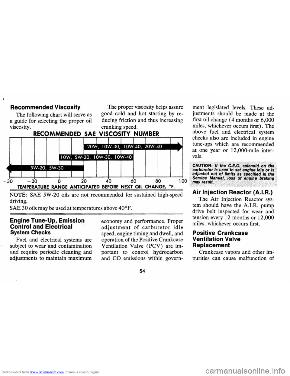
Downloaded from www.Manualslib.com manuals search engine Recommended Viscosity
The following chart will serve as
a guide for selecting the proper oil
viscosity. The
proper viscosity helps assure
good cold and hot starting by re
ducing friction and thus increasing
cranking speed.
OSITY NUMBER
-20 0 20 60 0
TEMPERATURE RANGE ANTICIPATED BEFORE NEXT OIL CHANGE. OF.
NOTE: SAE 5W-20 oils are not recommended for sustained high-speed
driving.
SAE 30 oils may be used at temperatures above 40°F.
Engine Tune-Up, Emission
Control and Electrical
System Checks
Fuel and electrical systems are
subject to wear and contamination
and require periodic cleaning and
adjustments to maintain maximum economy
and performance. Proper
adjustment of carburetor idle
speed, engine timing and dwell, and
operation of the Positive Crankcase
Ventilation Valve
(PCV) are im
portant to control hydrocarbon
and
CO emissions within govern-
54
ment legislated levels. These ad
justments should be made at the
first oil change
(4 months or 6,000
miles, whichever occurs first). The
above fuel and electrical system
checks also are included in engine
tune-ups which are recommended
at one year or 12,000-mile inter
vals.
Air Injection Reactor (A.I.R.)
The Air Injection Reactor sys
tem should have the A.I.R. pump
drive belt inspected for wear and
tension every 12 months or
12,000
miles, whichever occurs first.
Positive Crankcase
Ventilation
Valve
Replacement
Crankcase vapors and other im
purities can cause malfunction of