engine oil CHEVROLET CAMARO 1971 2.G Owner's Manual
[x] Cancel search | Manufacturer: CHEVROLET, Model Year: 1971, Model line: CAMARO, Model: CHEVROLET CAMARO 1971 2.GPages: 88, PDF Size: 34.8 MB
Page 59 of 88
Downloaded from www.Manualslib.com manuals search engine Distributor Cam Lubricator
6 Cylinder Engine -Rotate cam
lubricator
1800 at 12,000 mile in
tervals -Replace at
24,000 mile
intervals.
8 Cylinder Engine-Change cam
lubricator end for end at
12,000
mile intervals-Replace at 24,000
mile intervals.
Rear Axle
Standard -Every 4 months or
6,000 miles, whichever occurs
first, check lubricant level and add
lubricant, if necessary, to
fill to
level of filler plug hole.
Use SAE
80 or SAE 90 GL-5 Gear Lubri
cant.
Positraction -Same as standard
axle
but use only the special posi
traction lubricant available from
your Chevrolet Dealer.
Manual Transmissions
3-Speed and 4-Speed -Every
6,000 miles or 4 months-Check
at operating temperature and fill
as necessary to level of filler plug
hole with SAE
80 or SAE 90 GL-
5 Gear Lubricant.
Clutch Cross-Shaft -Every
36,000 miles or sooner if neces
sary -Remove the plug, install a
lubrication fitting
and lubricate
with water resistant
EP Chassis
Lubricant which meets
GM Speci
fication 6031M.
Automatic Transmission
Fluid Recommendations
General Motors DEXRON®
Automatic Transmission Fluid,
part no. 1050568 and United
Delco DEXRON® Automatic
Transmission Fluid, part no. 301-
RD, which have been especially
formulated and tested for use in
your automatic transmission are
recommended.
Other automatic
transmission fluids identified with
the
mark DEXRON@ are also
recommended.
56
Check the fluid level at each
engine oil change period.
To make
an accurate fluid level check:
1. Drive car several miles, making
frequent starts and stops, to
bring transmission up to normal
operating temperature (ap
proximately 180-190 OF) .
2.
Park car on a level surface.
3. Place selector lever
in "Park"
and leave engine running.
4. Remove dipstick and
WIpe
clean.
5. Reinsert dipstick until cap seats.
6. Remove dipstick and note read
ing.
If oil level is at or below the
"ADD" mark on the dipstick, oil
should be added as necessary.
One pint raises the level from ADD
to FULL.
Do not overfill.
Under normal driving condi
tions, the transmission fluid should
Page 62 of 88
Downloaded from www.Manualslib.com manuals search engine Standard Steering Gear
The steering gear is factory
filled with steering gear lubricant.
Seasonal change of this lubricant
should not be performed
and the
housing should
not be drained-no
lubrication
is required for the life
of the steering gear.
Every 36,000 miles, the gear
should be inspected for seal leak
age (actual solid
grease-not just
oily film).
If a seal is replaced or
the gear is overhauled, the gear
housing should be refilled with
Part No. 1051052 (13 oz. con
tainer)
Steering ' Gear Lubricant
which meets
GM Specification GM
4673M, or its equivalent.
NOTE: Do not use EP Chassis
Lube, meeting
GM Specification
GM 6031 M, to lubricate the gear.
DO NOT OVER-FILL the gear
housing.
Power Steering Pump
Every 6,000 miles or 4 months
Check level in pump reservoir. Fill
pump reservoir
as required with
GM Power Steering Fluid or, if
this
is not available, DEXRON®
Automatic Transmission fluid.
Oil
should be at operating tempera
ture
and wheels in straight ahead
position when checking
or filling
operation is performed to ensure
against over-filling.
Hood Latches
Every 4 months or 6,000 miles,
whichever occurs first, lubricate
hood latch assembly
and hood
hinge assembly as follows:
1. Wipe off any accumulation of
dirt
or contamination on latch
parts.
2. Apply Lubriplate
or equivalent
to latch pilot bolts
and latch
locking plate.
3. Apply light engine oil to
all
59
pivot points in release mecha
nism, as well as primary
and sec
ondary latch mechanisms.
4. Lubricate hood hinges.
5. Make hood hinge
and latch
mechanism functional check to
assure the assembly is working
correctly.
Air Conditioning
Have your Chevrolet Dealer
check your Air Conditioning sys
tem at some time during the winter
months to
be sure there has been
no loss in cooling output. During
the summer, see your Chevrolet
Dealer immediately if you suspect
the system is
not performing as it
should.
NOTE: On vehicles equipped with
a
Four Season Air Conditioning
System, the system will not operate
below ambient temperatures of
30oP. regardless of control posi
tion.
Page 63 of 88
Downloaded from www.Manualslib.com manuals search engine Cooling System Care
Checking the coolant level at
each engine oil change. Level
should be
3" below bottom of filler
neck when cold.
Coolant Recommendations
The inhibited year-around cool
ant, used to
fill the cooling system
at the factory,
is a high quality so
lution that meets General Motors
Specifications 1899-M. This fac
tory-fill coolant solution
is formu
lated to withstand two full calendar
years of normal operation without
draining, provided the same con
centration of coolant
is added if the
system needs additional fluid be
tween drain periods. The original
factory-fill coolant provides freez
ing protection to
-20°F (-32°F
in Canada).
Every two years, the cooling sys
tem should be serviced as follows:
1. Drain coolant, when hot,
through the radiator drain valve.
2. Close valve and add sufficient
plain· water to
fill system.
3. Run engine until normal operat
ing temperature
is reached.
4. Drain and refill the system as
described in steps 1, 2, and 3 a
sufficient number of times until
the drained liquid
is colorless.
5. Allow system to drain com
pletely and then close radiator
drain valve tightly.
6.
Add the necessary amount of
high quality inhibited glycol
base coolant meeting GM
Speci
fication 1899-M to provide the
required freezing and corrosion
protection
(at least to O°F.)
7. Run engine until normal oper
ating temperature
is reached.
8. Check and adjust level of cool
ant after system has cooled
suffi
ciently to remove radiator cap.
60
NOTE: Addition of supplemental
additives and other available ma
terials which have not been specifi
cally approved by GM are not nor
mally required in your car. Use of
these materials will result in un
warranted operating expense.
It is the owner's responsibility to
keep the freeze protection at a level
commensurate with the tempera
tures which may occur in the area
in which the vehicle will be oper
ated. Regardless of whether freez
ing temperatures are
or are not ex
pected, cooling system protection
should be maintained at least to
OaF to provide adequate corrosion
protection. When coolant addi
tions are required because of cool
ant loss or to provide additional
protection against freezing at tem
peratures lower than
-20°F,
(-32°F in Canada), a sufficient
amount of an ethylene glycol base
Page 69 of 88
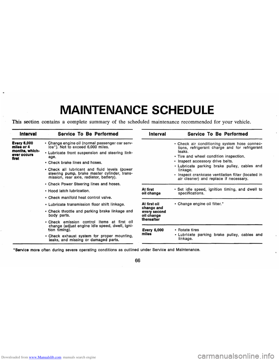
Downloaded from www.Manualslib.com manuals search engine MAINTENANCE SCHEDULE
This section contains a complete summary of the scheduled maintenance recommended for your vehicle.
Intarval
Every 6,000 mile. or 4 month., which· ever occur. flrat
Service To Be Performed
• Change engine oil (normal passenger car serv
ice"). Not to exceed 6,000 miles.
•
Lubricate front suspension and steering linkage.
• Check brake lines and hoses.
• Check all lubricant and fluid levels (power
steering pump, brake master cylinder, transmission, rear axle, radiator, battery).
• Check Power Steering lines and hoses.
• Hood latch lubrication.
• Check manifold
heat control valve.
•
Lubricate transmission floor shift linkage.
• Check
throttle and parking brake linkage and
body parts.
• Check emission control items at first oil
change (adjust engine idle speed, dwell, ignition timing) .
• Check exhaust system for proper mounting , leaks, and missing or damaged parts.
Interval
At first oil change
At first
oil change and
every second
oil change
thereafter
Every
6,000
mlle&
Service To Be Performed
• Check air conditioning system hose connections, refrigerant charge and for refrigerant
leaks.
• Tire and wheel condition inspection.
• Inspect accessory drive belts.
•
Lubricate parking brake pulley, cables and linkage.
Inspect crankcase ventilation filter (located in
air cleaner) and replace if necessary.
• Set idle speed , ignition timing, and dwell to
specifications.
• Change engine oil filter."
•
Rotate ti res • Lubricate parking brake pulley, cables and
linkage .
·Servlce more often during severe operating conditions as outlined under Service and Maintenance.
66
Page 70 of 88
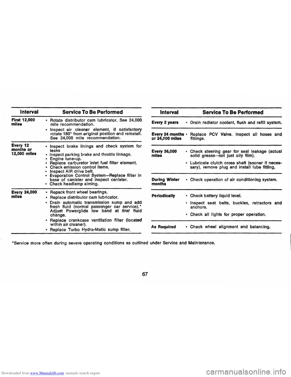
Downloaded from www.Manualslib.com manuals search engine Interval
First 12,000 miles Every 12
months
or 12,000 miles
Every
24,000 miles
Service To Be Performed
• Rotate distributor cam lubricator. See 24,000 mile recommendation.
• Insp .ect air cleaner element, if satisfactory
rotate 1800 from original position and reinstall. See 24,000 mile recommendation.
• Inspect brake linings and check system for
leaks
• Inspect parking brake and throttle linkage. • Engine tune-up.
Replace carburetor 'Inlet fuel filter element. • Check emission control items. • Inspect AIR drive belt.
Evaporation Control System-Replace filter in
base of canister and inspect canister. • Check headlamp aiming.
• Repack front wheel bearings.
• Replace distributor cam lubricator. • Drain automatic transmission sump and add
fresh fluid (normal passenger car service).' Adjust Powerglide low band at first fluid
change.
• Replace crankcase ventilation filter (located
within air cleaner).
• Replace Turbo Hydra-Matic sump filter.
Interval Service To Be Performed
Every 2 years • Drain radiator coolant, flush and refill system.
Every
24 months· Replace PCV Valve. Inspect all hoses and or 24,(100 miles fittings.
Every
36,000 • Check steering gear for seal leakage (actual
miles solid grease-not just oily film).
• Lubricate clutch cross shaft (sooner if necessary), remove plug and install lube fittIng.
During Winter
• Check operation of air conditioning system.
months
Periodically • Check battery liquid leve/.
• Inspect seat belts, buckles, retractors and
anchors.
• Check all lights for proper operation.
As Required
• Check wheel alignment and balancing.
'Service more often during severe operating conditions as outlined under Service and Maintenance.
67
Page 72 of 88
Downloaded from www.Manualslib.com manuals search engine The chart on the previous page, and the information on the pages
which
follow, contains information designed to aid the average
driver to discover, and possibly correct, conditions resulting in minor
mechanical
difficulties in his car. The chart, designed to point out
possible solutions to several of the most common automotive mal
functions and point out a logical checking sequence, will lead step
by step to the most likely causes and corrective procedures. If, after
making the checks and adjustments suggested, the source of the
trouble has not been found and corrected, it is strongly recom
mended that an Authorized Chevrolet Dealer inspect the vehicle and
make whatever repairs
or adjustments are necessary.
FUEL SYSTEM AND ENGINE
If the ignition switch will cause the engine to "turn over" or
"crank" but the car will not start, check Steps A through D below.
NOTE:
If continual "Rooding" of the carburetor is evidenced by a
carbur.tor wet with
fuel or black exhaust smoke, perform the
operation suggested in paragraph D only.
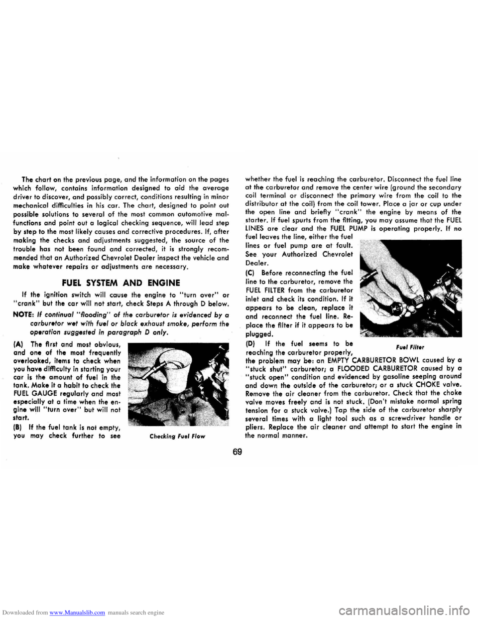
(A) The first and most obvious,
and one of the most frequently overlooked, items to check when
you have difficulty in sta rting you r car is the amount . of fuel in the
tank. Make it a habit to check the FUEL GAUGE regularly and most especially at a time when the engine will "turn over" but will not
start.
(8)
If the fuel tank is noi empty,
you may cheek further to see Checking Fllel Flow
69
whether the fuel is reaching the carburetor. Disconnect the fuel line at the carburetor and remove the center wire (ground the secondary coil terminal or disconnect the primary wire from the coil to the distributor at the coil) from the coil tower. Place a jar or cup under
the open line and briefly "cronk" the engine by means of the
starter. If fuel spurts from the fitting, you may assume that the FUEL LINES are clear and the FUEL PUMP is operating properly. If no fuel leaves the line, either the fuel
lines
or fuel pump are at fault.
See. your Authorized Chevrolet
Dealer.
(C) Before reconnecting the fuel
line
to the carburetor, remove the
FUEL FILTER from the carburetor
inlet and check its condition. If it
appears to be clean, replace it
and reconnect the fuel line. Re
place the filter if it appears to be
plugged.
(D) If the fuel seems to be
reaching the
carburetor properly, File' Fllt.r
the problem may be: an EMPTY CARBURETOR BOWL caused by a "stuck shut" carburetor; a FLOODED CARBURETOR caused by a "stuck open" condition and evidenced by gasoline seeping around
and down the outside of the carburetor; or a stuck CHOKE valve. Remove the air cleaner from the carburetor. Check that the choke valve moves freely and is not stuck. (Don't mistake normal spring
tension for a stuck valve.) Tap the side of the carburetor sharply
several times with a light tool such as a screwdriver handle or pliers. Replace the air cleaner and attempt to start the engine in
the
normal manner.
Page 73 of 88
Downloaded from www.Manualslib.com manuals search engine (E) If the car will start but stalls when hot or has a rough idle, you can suspect a faulty IDLE ADJUSTMENT, a malfunctioning AUTOMATIC CHOKE or an extremely dirty and blocked AIR CLEANER ELEMENT. Replace paper element air cleaner if necessary. Idle adjustment or automatic choke service (other than that outlined in paragraph D above) should be performed by your Chevrolet Dealer.
If the above Fuel System checks and the checks suggested under the Electrical System following do not correct the malfunction, it is recommended that you return to your Authorized Chevrolet Dealer for further checks, adjustments or repairs.
ELECTRICAL SYSTEM
If, when the ignition key is turned to "Start", the engine will not
turn over, you have good reason to suspect electrical trouble.
NOTE: Never remove Delcotron bat lead without first disconnecting battery ground cable.
(F) When there is no response at all to attempts to start the car, check the obvious-your AUTOMATIC TRANSMISSION SELECTOR LEVER must be in Neutral or Park position before the engine can be started. Turning the IGNITION SWITCH rapidly back and forth several times will sometimes correct a poor internal switch contact.
(G) The BATIERY may be discharged. If so, lights will be dim and the horn will have a poor tone if it will blow at all.
Usually
a garage recharge will be necessary to return the battery to operation. Occasionally, however, a long drive will recharge the battery.
NOTE: If the battery is determined to be dead, and for no apparent reason, have your Authorized Chevrolet Dealer check the
battery, the GENERATOR and the VOLTAGE REGULATOR. GENERATOR trouble should already have been indicated by the gene~ator indicator light on the instrument panel.
70
POOR BATIERY CONNECTIONS may be suspected if the car has operated properly a short time before and now not even the horn will operate. Check both ends of both battery cables. If the con
nections are corroded, a car may sometimes be restored to operation by removing all cable ends, scraping all contacting surfaces clean with a pen knife, and reassembling. If the cables are broken,
they must be replaced. The power supply should now be restored unless the battery is dead.
(H) If, however, the lights and horn work properly but the starter will still not turn over, check the STARTER connections. A "click" from the starter solenoid indicates that the wiring to the starter is properly installed. If the wiring seems to be clean and tightly installed, the trouble is probably in the starter itself and should be referred to your Authorized Chevrolet Dealer.
When the engine will "turn over" but will not start, the following items may be checked along with the Fuel Systems Checks listed
previously.
(I) With a clean dry cloth, wipe the ceramic portions of the spark plugs dry. In particularly damp or rainy weather dampness may be the cause of not starting, especially when the engine is cold.
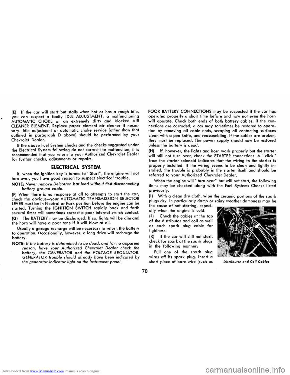
(J) Check the cables at the top of the distributor and coil as well as each spark plug cable for tightness.
(K) If the car will still not start, check for spark at the spark plugs in the following manner:
Pull one of the spark plug wires off its spark plug. Insert a
short piece of bare wire (such as Distributor and Coil Cables
Page 74 of 88
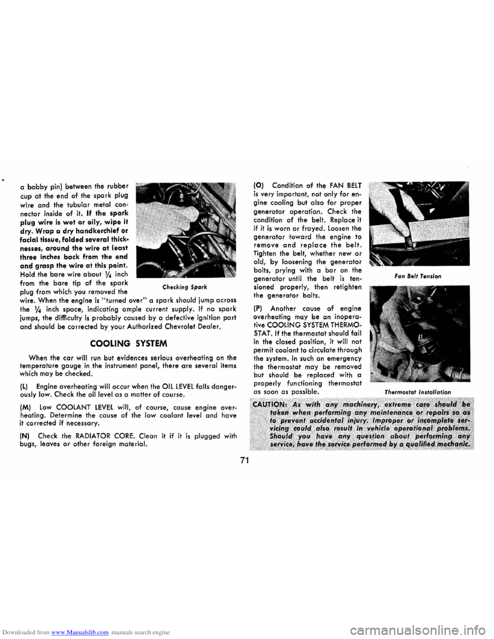
Downloaded from www.Manualslib.com manuals search engine a bobby pin) between the rubber
cup at the end of the spark plug
wire
and the tubular metal con
nector inside of it. If the spark plug wire is wet or oily, wipe it
dry. Wrap a dry handkerchief or facial tissue, folded several thick·
nesses, around the wire at least
three inches back from the end
and grasp the wire at this point.
Hold the bare wire about 1f4 inch
from the
bare tip of the spark
plug from which you removed the Checking Spark
wire. When the engine is "turned over" a spark should jump across
the 1f4 inch space, indicating ample current supply. If no spark
jumps, the difficulty is probably caused by a defective ignition part
and should be corrected by. your Authorized Chevrolet Dealer.
COOLING SYSTEM
When the car will run but evidences serious overheating on the temperature gauge in the instrument panel, there are several items
which may be checked.
(L) Engine overheating will occur when the OIL LEVEL falls dangerously low. Check the oil level as a matter of course.
(M) Low COOLANT LEVEL will, of course, cause engine over
heating. Determine the cause of the low coolant level and have
it corrected if necessary.
(N) Check the RADIATOR CORE. Clean it if it is plugged with
bugs, leaves or other foreign material.
71
(0) Condition of the FAN BELT is very important, not only for engine cooling but also for proper
generator operation. Check the
condition of the belt. Replace it if it is worn or frayed. Loosen the generator toward the engine to remove and replace the belt. Tighten the belt, whether new or old, by loosening the generator bolts, prying with a bar on the generator until the belt is ten
sioned properly, then retighten
the
generator bolts.
(P) Another cause of engine overheating may be an inoperative COOLING SYSTEM THERMOSTAT. If the thermostat should fail in the closed position, it will not
permit coolant to circulate through
the system.
In such an emergency the thermostat may be removed
but should be replaced with a properly functioning thermostat as soon as possible.
Fan Belt Tension
Thermostat
Installation
Page 75 of 88
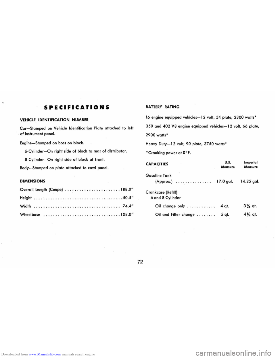
Downloaded from www.Manualslib.com manuals search engine SPECIFICATIONS
VEHICLE IDENTIFICATION NUMBER
Car-Stamped on Vehicle Identification Plate attached to left
of instrument panel.
Engine-Stamped on boss on block.
6-Cylinder-On right side of block to rear of distributor.
S-Cylinder-On right side of block at front.
Body-Stamped on plate attached to cowl panel.
DIMENSIONS
Overall Length (Coupe) ....................... 18S.0"
Height ..................................... 50.5"
Width .................................... 74.4"
Wheelbase ................................ 108.0"
72
BATTERY RATING
L6 engine equipped vehicles-12 volt, 54 plate, 2300 watts'
350 and 402 VS engine equipped vehicles-12 volt, 66 plate,
2900 watts'
Heavy Duty-12 volt, 90 plate, 3750 watts'
'Cranking power at O°F.
CAPACITIES
Gasoline Tank
(Approx.)
Crankcase
(Refill)
6 and S Cylinder
Oil change only
u.s. Measure
17.0 gal.
4 qt.
Oil and Filter change . . . . . . .. 5 qt.
Imperial Measure
14.25 gal.
3% qt.
4 % qt.
Page 76 of 88
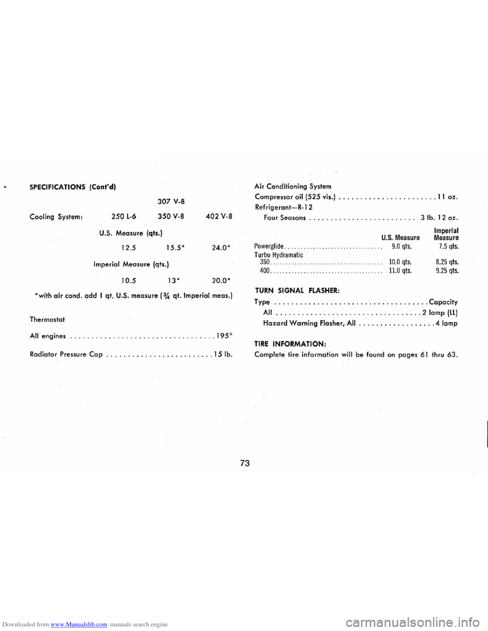
Downloaded from www.Manualslib.com manuals search engine SPECIFICATIONS (Cont'dl
Cooling System: 250 L-6
307 V-8
350 V-8
U.S. Measure (qts.)
12 .5
15 .5'
Imperial Measure (qts.)
10.5 13'
402 V-8
24 .
0'
20.0'
'with air condo add 1 qt. U.S. measure (3~ qt. Imperial meas.)
Thermostat
All engines ... .... ........................... 1950
Radiator Pressure Cap .. ....................... 15 lb.
73
Air Conditioning System
Compressor oil
(525 vis.) ....................... 11 oz.
Refrigerant-R-12
Four Seasons. . . . . . . . . . . . . . . . . . . . . . . .. 3 lb. 12 oz.
U.S. Measure
Powerglide. . . . .. . .. .. . .. . .. . .. . .. . .. 9.0 qts. Turbo Hydramatic 350. . . . . . . . . . . . . . . . . . . . . . . . . . . . . . . . . . . .. 10.0 qts.
400..................................... 11.0 qts.
TURN SIGNAL FLASHER:
Imperial Measure 7.5 qts.
8.25 qts.
9.25 qts.
Type .................................... Capacity
All .................. ................ 2 lamp (LL)
Hazard Warning Flasher, All .................. 4 lamp
TIRE INFORMATION:
Complete tire information will be found on pages 61 thru 63.