brakes CHEVROLET CAMARO 1971 2.G Owners Manual
[x] Cancel search | Manufacturer: CHEVROLET, Model Year: 1971, Model line: CAMARO, Model: CHEVROLET CAMARO 1971 2.GPages: 88, PDF Size: 34.8 MB
Page 17 of 88
Downloaded from www.Manualslib.com manuals search engine Driving with the Chevrolet Automatic Transmissions
The Powerglide and the Turbo
Hydra-matic 350 and 400 are com
pletely automatic transmissions.
All replace the standard clutch
and
transmission.
Powerglide, Turbo Hydra
Malic
350 and Turbo Hydra
Matic
400
After starting the engine with the
selector lever in N (Neutral)
or P
(Park) position select the range de- sired
(see tables)
and depress the
accelerator.
All Automatic Transmissions
A gradual start with a steady in
crease in accelerator pressure will
result in best possible fuel economy.
Rapid acceleration for fast starts
will result in greater fuel consump
tion.
Automatic transmission shift
quadrants of all OM cars continue
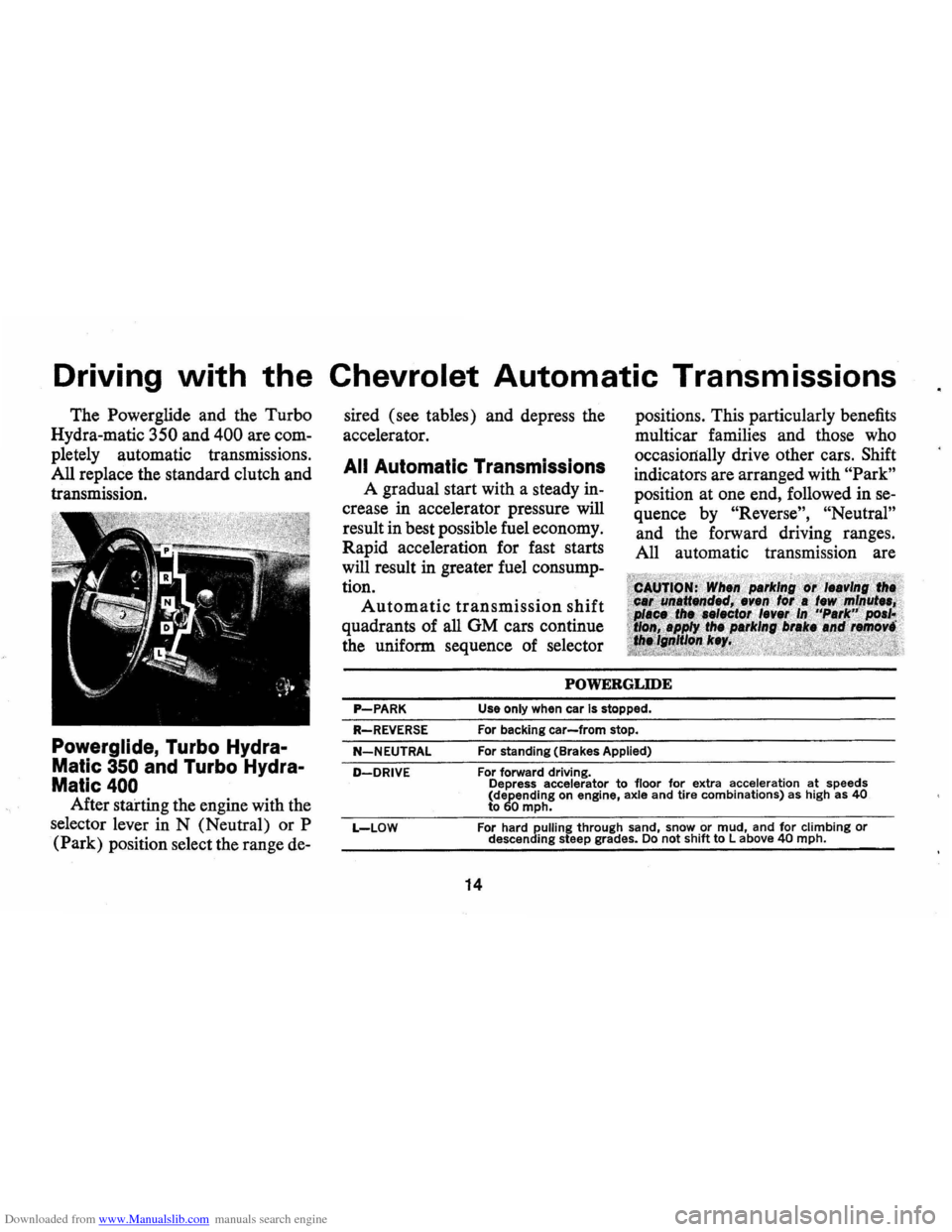
the uniform sequence of selector positions.
This particularly benefits
multicar families
and those who
occasionally drive other cars.
Shift
indicators are arranged with "Park"
position at one end, followed in se
quence by
"Reverse", "Neutral"
and the forward driving ranges.
All automatic transmission are
POWERGLIDE
P-PARK Use only when car Is stopped.
R-REVERSE
N-NEUTRAL
D-DRIVE
L-LOW
For backing car-from stop.
For standing (Brakes Applied)
For forward driving.
Depress accelerator
to floor for extra acceleration at speeds
(depending on engine, axle and tire combinations) as high as 40 to 60 mph.
For hard pulling through sand, snow or mud, and for climbing or descending steep grades. Do not shift to Labove 40 mph.
14
Page 18 of 88
Downloaded from www.Manualslib.com manuals search engine equipped with a starter safety
switch designed to permit starting
the engine only when the trans
mission
is in the "Park" or "Neu
tral"
position. For additional
engine braking effect,
as sometimes
needed in mountainous driving,
place the transmission in an inter
mediate or low range.
Column Shifl Lever
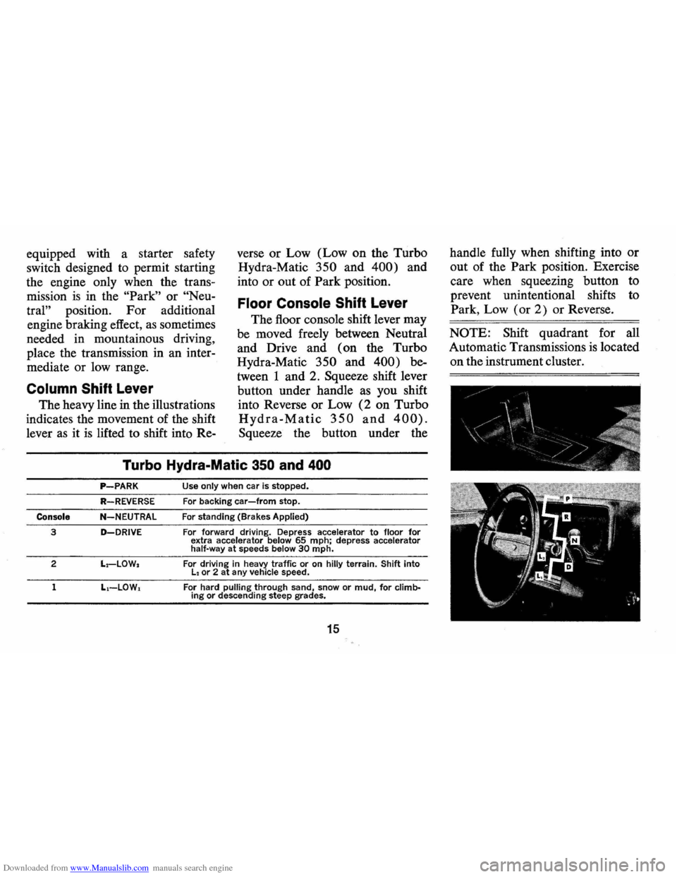
The heavy line in the illustrations
indicates the movement of the shift
lever
as it is lifted to shift into Re- verse
or Low (Low on the Turbo
Hydra-Matic
350 and 400) and
into or out of Park position.
Floor Console Shift Lever
The floor console shift lever may
be moved freely between Neutral
and Drive and ( on the Turbo
Hydra-Matic
350 and 400) be
tween 1 and 2. Squeeze shift lever
button under handle as you shift
into Reverse or Low
(2 on Turbo
Hydra-Matic 350 and 400).
Squeeze the button under the
Turbo Hydra-Malic 350 and 400
P-PARK
R-REVERSE
Console N-NEUTRAL
3 D-DRIVE
2 L.-LOW.
1 L.-LOW.
Use only when car is stopped.
For backing car-from stop.
For standing (Brakes Applied)
For forward driving. Depress accelerator to floor for extra accelerator below 65 mph; depress accelerator
half-way at speeds below 30 mph.
For driving in heavy traffic or on hilly terrain. Shift into L. or 2 at any vehicle speed.
For
hard pulling through sand, snow or mud, for climbing or descending steep grades_
15
handle fully when shifting into or
out of the Park position. Exercise
care when squeezing button to
prevent unintentional shifts to
Park, Low (or
2) or Reverse.
NOTE: Shift quadrant for all
Automatic Transmissions
is located
on the instrument cluster.
Page 19 of 88
Downloaded from www.Manualslib.com manuals search engine Driving with Manual Transmissions
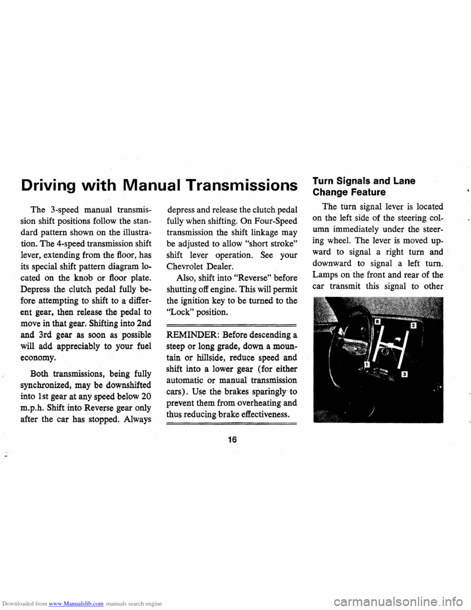
The 3-speed manual transmis
sion shift positions follow the
stan
dard pattern shown on the illustra
tion. The 4-speed transmission shift
lever, extending from the floor,has
its special shift pattern diagram
lo
cated on the knob or floor plate.
Depress the clutch pedal fully
be
fore attempting to shift to a differ
ent gear, then release the pedal to
move in that gear. Shifting into 2nd
and 3rd gear
as soon as possible
will add appreciably to your fuel
economy.
Both transmissions, being fully
synchronized, may be downshifted
into 1st gear at any speed below
20
m.p.h. Shift into Reverse gear only
after the car has stopped. Always depress
and release the clutch pedal
fully when shifting.
On Four-Speed
transmission the shift linkage may
be adjusted to allow
"short stroke"
shift lever operation. See your
Chevrolet Dealer.
Also, shift into
"Reverse" before
shutting
off engine. This will permit
the ignition key to be turned to the
"Lock" position.
REMINDER: Before descending a
steep or long grade, down a moun
tain or hillside, reduce speed and
shift into a lower gear (for either
automatic or manual transmission
cars).
Use the brakes sparingly to
prevent them from overheating and
thus reducing brake effectiveness.
16
Turn Signals and Lane
Change Feature
The turn signal lever is located
on the left side of the steering
col
umn immediately under the steer
ing wheel. The lever is moved up
ward to signal a right turn and '
downward to signal a left turn.
Lamps on the front and rear of the
car transmit this signal to other
Page 20 of 88
Downloaded from www.Manualslib.com manuals search engine motorists and pedestrians. The ig
nition switch must be in the "ON"
position in order for the turn sig
nals to be operational. This feature
prevents battery drain if the lever
is left in an "ON" position when
your car
is not in use.
In a normal turning situation
such
as turning a corner, the turn
signal is cancelled automatically
after the turn
is completed. How
ever, in some driving maneuvers
such
as changing lanes on an ex
pressway, the steering wheel
is not
turned back sufficiently after com
pleting the turn to automatically
cancel the turn signal. For con
venience in such maneuvers, the
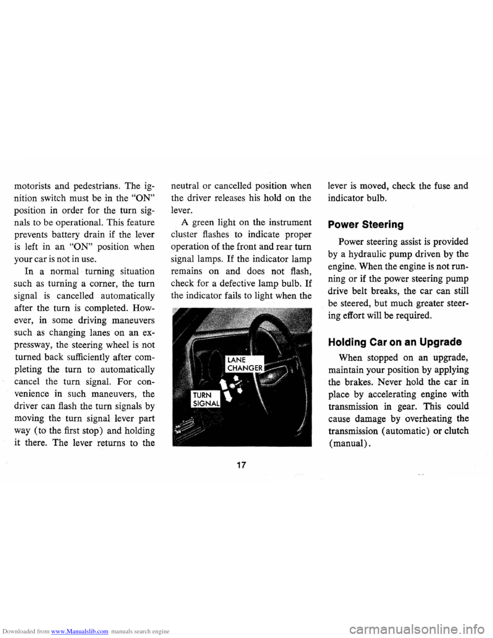
driver can flash the turn signals by
moving the turn signal lever part
way (to the first stop) and holding
it there. The lever returns to the neutral
or cancelled position when
the driver releases his hold on the
lever.
A green light on the instrument
cluster flashes to indicate proper
operation of the front and rear
tum
signal lamps. If the indicator lamp
remains on and does not flash,
check for a defective lamp bulb.
If
the indicator fails to light when the
17
lever is moved, check the fuse and
indicator bulb.
Power Steering
Power steering assist is provided
by a hydraulic pump driven by the
engine. When the engine
is not run
ning
or if the power steering pump
drive belt breaks, the car can still
be steered, but much greater steer
ing effort will be required.
Holding Car on an Upgrade
When stopped on an upgrade,
maintain your position by applying
the brakes. Never hold the car in
place by accelerating engine with
transmission in gear. This could
cause damage by overheating the
transmission (automatic) or clutch
(manual).
Page 24 of 88
Downloaded from www.Manualslib.com manuals search engine Generator Indicator Light
This light provides a quick check
on the generating system of your
car. The red light will go on when
the ignition key
is in the "on" posi
tion, but before the engine is
started. After the engine starts, the
light should go out and remain out.
If the light remains on when engine
is running, have your Authorized
Chevrolet Dealer locate and correct
the trouble
as soon as possible.
Engine Temperature
Indicator Light
This indicator light is provided
in the instrument cluster to quickly
warn of an overheated engine. With
the ignition
switGh in the START
position, the red TEMP indicator
will light to let you know that it
is
operating properly.
When the engine
is started, the
red light will go out immediately.
It will light up at no other time
unless for some reason the engine
reaches a dangerously high
oper
ating temperature. If the red light
should come on, the engine must be
stopped until the cause of the
over
heating is corrected. Glance at in
strument cluster frequently as you
drive to see if this light
is on.
Brake System Warning
Light
The service brake system is de
signed so that half of the brake sys
tem will provide some braking ac
tion in the event of a hydraulic leak
in the other half of the system.
When the brake apply system
is not
operating properly, a warning light
located at lower left of instrument
cluster (speedometer face) will
glow continuously when the
igni
tion is on after the brakes have been
firmly applied.
On cars equipped
with drum brakes, the light will go
21
out when foot is removed from
brake pedal.
• As a check on bulb condition the
light should glow with the
park
ing brake applied and the igni
tion on. (Light is also a reminder
to release parking brake.)
• Have system repaired if light
does not come on during check.
• This warning light is nota sub
stitute for the visual check of
brake fluid level required
as part
of normal maintenance.
If the light glows red:
• The parking brake is not fully re
leased or,
• The service brake system is par
tially inoperative.
What to do:
1. Check that the parking brake is
released.
2. Pull off the road and stop, care
fully-remembering that:
Page 34 of 88
Downloaded from www.Manualslib.com manuals search engine FLOOR CONTROLS
Braking System
The service brake system is de
signed for braking performance
under a wide range of driving con
ditions even when the vehicle
is
loaded to its full rated vehicle load.
Power Brakes
• Cars with power brakes can
make two or more brake stops
using reserve power assist after
the engine
is off.
• When reserve power is ex
hausted, the vehicle can still be
stopped by applying greater
force to the pedal.
Parking Brake
• To set parking brake, fully de
press foot pedal at far left side.
• For maximum holding power,
depress regular brake pedal with
the other foot at the same time.
• To release parking brake, pull
"BRAKE RELEASE" lever on
lower left instrument panel.
• Never drive car with parking
brake set
as this may overheat or
otherwise damage rear brakes.
REMINDER: Brake pedal travel
should not be obstructed by im
proper floor mats or other interfer
ing material under the pedal.
NOTE: "Riding the brake" by rest
ing your foot on the brake pedal
when not intending to brake can
cause abnormally high brake tem
peratures, excessive lining wear
and possible damage to the brakes.
31
REMINDER: Brake linings should
be inspected for wear by a qualified
mechanic at least once a year
or
every 12,000 miles, whichever oc
curs first. More frequent inspec
tions should be made if driving con
ditions in your area, such
as traffic
or terrain, or techniques of indi
vidual drivers result in frequent
brake applications. Your Chevrolet
dealer
is best qualified to advise you
as to how often this inspection
should be performed. When brakes
require relining, use those Genuine
General Motors
Parts specifically
recommended for your car, and
Delco, brake fluid as required.
Automatic Brake Adjusters
• Brakes on this car are self-adjust
ing, designed to eliminate peri
odic brake adjustments.
Page 35 of 88
Downloaded from www.Manualslib.com manuals search engine • Drum brake adjustment is made
automatically
as the brakes are
applied while car
is moving back
wards.
• Disc brake adjustment is made
automatically with each brake
application.
• If excess brake pedal travel de
velops, drive alternately back
ward and forward (several
times) and apply brakes firmly
in each direction.
• See your dealer if normal pedal
travel
is not restored, or if there
is a
rapid increase in pedal
travel, which could be a sign of
other brake trouble.
Clutch Adjustment
Clutch adjustment should be
checked and adjusted periodically
as necessary to compensate for
clutch facing wear. To check,
de
press pedal by hand until resistance
is felt. Free travel of pedal should
be approximately one inch; if very little
or no free travel
is evident,
clutch adjustment
is required.
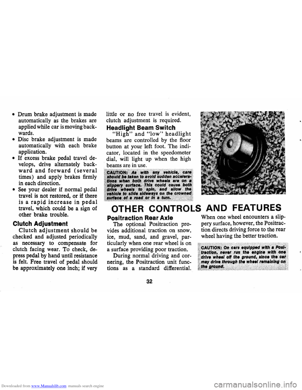
Headlight Beam Switch
"High" and "low" headlight
beams are controlled by the floor
button at your left foot. The
indi
cator, located in the speedometer
dial, will light up when the high
beams are in use.
OTHER CONTROLS AND FEATURES
Positraction Rear Axle
The optional Positraction pro
vides additional traction on snow,
ice, mud, sand, and gravel,
par
ticularly when one rear wheel is on
a surface providing poor traction.
During normal driving and
cor
nering, the Positraction unit func
tions as a standard differential.
32
When one wheel encounters a slip
pery surface, however, the Positrac
tion directs driving force to the rear
wheel having the better traction.
Page 36 of 88
Downloaded from www.Manualslib.com manuals search engine SAFETY CHECKS
Your Camaro not only conforms to all U.S. Fed
eral Motor Vehicle
Safety Standards applicable at
time of manufacture, but also incorporates other im
portant General Motors safety features. Even with
these safety features, however, continued safe and
dependable operation depends greatly upon regular
vehicle maintenance.
This section discusses the various components and
systems of your vehicle that should be checked regu-
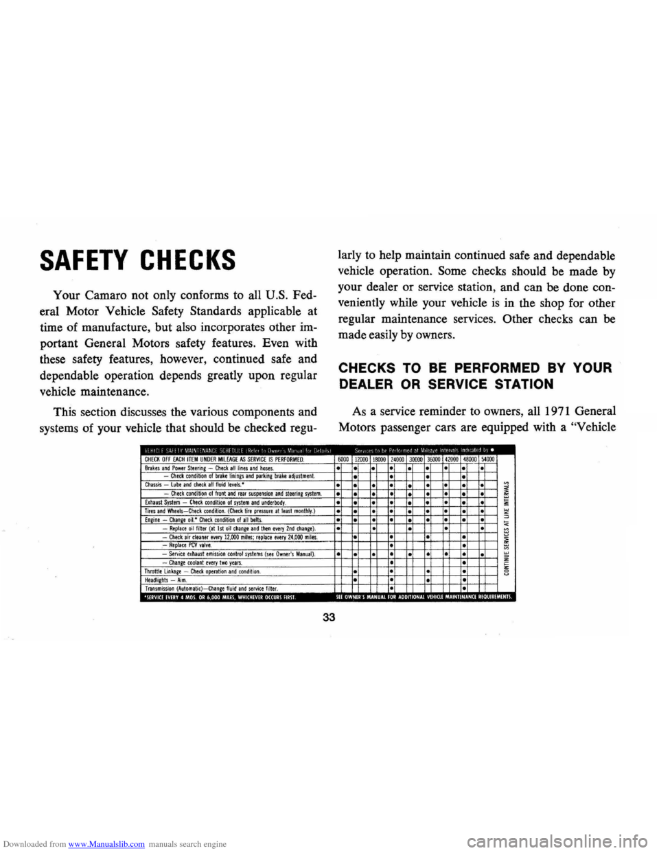
CHECK OFF EACH ITEM UNDER MIlEAGE AS SERVICE IS PERFORMED. Brakes and Power Steering -Check all lines and hoses. Check condition of brake linings and parking brake adjustment. Chassis lube and check all fluid levels,· Check condition of front and rear suspension and steerine system. Exhaust System -Check condition of system and underbody. Tires and Wheels-Check condition. (Check tire pressure at least monthly.) Engine -Change oil.· Check condition 01 all belts. -Replace oil filter (at 1st oil change and tllen every 2nd chanie). -Check air cleaner every 12,000 miles; replace every 24,000 miles. .-Replace PCV valve. -Service exhaust emission control systems (see Owner's Manual). -Change toolanl every Iwo years. Throttle linkage -Check operation and condition . Headlights -Aim. Transmission (Automatic)-Change fluid and service filter. 0 ,', III · 0
33
larly to help maintain continued safe and dependable
vehicle operation.
Some checks should be made by
your dealer or service station, and can be done con
veniently while your vehicle
is in the shop for other
regular maintenance services.
Other checks can be
made easily by owners.
CHECKS TO BE PERFORMED BY YOUR
DEALER OR SERVICE STATION
As a service reminder to owners, all 1971 General
Motors passenger cars are equipped with a
"Vehicle
6000 12000 18000 24000 30000 36000 41000 48000 )4000
• •
• •
• • • •
• • •
• •
• • • • • • •
• • • • • • • • • • •
• • • •
• • •
• •
• • • •
• • • • • • •
• • • • •
• •
• •
• • •
• •
• • • • •
• • • • • •
•
• • •
· • · •
• • • • •
• 0 o· 00 0 ·
0
Page 37 of 88
Downloaded from www.Manualslib.com manuals search engine Safety Maintenance Schedule" on the inside of the
glove box door
as illustrated.
The schedule lists the various safety checks to be
performed at regularly scheduled intervals,
as well
as some of the other important vehicle maintenance
requirements. You are urged to check
off each item
on the schedule after the operation has been per
formed. Following are further details on the safety
check items:
Checks To Be Made At Oil Change Intervals
(4 months or 6,000 miles, whichever comes
first)
• Brake Lines and Hoses -Check for proper at
tachments, leaks, cracks, chafing, deterioration,
etc. Any questionable parts noted should be re
placed or repaired immediately.
• Fluid Levels-Check level of fluid in brake master
cylinder, power steering pump, radiator, engine,
axle and transmission. Any significant
loss could
mean that a malfunction
is developing in the sys
tem and corrective action should be taken imme
diately.
On cars with disc brakes, a low fluid level
in the front brake master cylinder reservoir could
34
also be an indicator that disc brake pads need
replacing.
• Front and Rear Suspension and Steering Sys
tem-Check for damaged or missing parts, or parts
showing visible signs of excessive wear or lack of
lubrication. Questionable parts should be replaced
by a qualified mechanic without delay.
• Exhaust System -Check complete exhaust sys
tem and nearby body areas and trunk lid for
broken, damaged, missing or mispositioned parts,
open seams, holes, loose connections
or other de
terioration which could permit exhaust fumes to
seep into the trunk or passenger compartment. Any
defects should be corrected immediately. To help
insure continued integrity, exhaust system pipes
rearward of the
muffler must be replaced whenever
a new
muffler is installed.
• Tires and Wheels -Check tires for excessive
wear, nails, cuts or other damage. Make certain
wheels are not bent
~nd wheel nuts are tight. Un
even or abnormal tire wear may indicate the need
for alignment service. Check tire inflation pressure
at least monthly, or more often
if daily visual
inspection indicates the need.
Page 39 of 88
Downloaded from www.Manualslib.com manuals search engine For further details on the engine and transmission
items listed on the
"Vehicle Safety Maintenance
Schedule," and for other recommended maintenance,
refer
to the "Service and Maintenance" and "Air
Pollution. Control" Sections of this manual.
CHECKS lOBE PERFORMED
BY OWNER
Listed below are the safety checks that should be
made by the owner . These checks should be made at
least every 4 months or
6,000 miles, whichever occurs
first , or more often when so indicated . Any
deficien
cies should be brought to the attention of your dealer
or service station, so the advice of a qualified mech
anic is available regarding the need for repairs or
replacements.
• Anti-Theft Lock-Check for proper operation by
attempting to turn key to
LOCK position in the
various transmission gears with
car stationary. Key
should
tum to LOCK position only when trans
mission control is in PARK on automatic trans
mission models or in REVERSE on manual trans
mission models.
• Seat Belts-Check lap and shoulder belts as well
as buckles, retractors and anchors for loose con-
36
nections, damage and positive latching action.
• Windshield Wipers and Washers-Check con
dition and alignment of wiper blades. Check
amount and direction of fluid sprayed by washers
during use.
• Defrosters-Check performance by turning con
trols to "de-ice" and "Hi" fan speed and noting
amount of air directed against the windshield.
• Wheel Alignment and Balance-In addition to
abnormal tire wear the need for wheel alignment
service may be indicated by a pull to the right or
left when driving on a straight level road. The need
for wheel balancing may be indicated by a
vibra
tion at the steering wheel while driving.
• Parking Brake and "Park" Mechanism-Check
parking brake holding ability by parking on a fairly
steep hill and restraining the vehicle with the
parking brake only.
On cars with automatic trans
missions, check the holding ability of the "Park"
mechanism by releasing all brakes after the trans
mission selector lever has been placed in the "P"
position.
• Lights -Check license plate lights, side marker
lights , headlamps, parking lamps, tail lamps , brake