air condition CHEVROLET CAMARO 1974 2.G User Guide
[x] Cancel search | Manufacturer: CHEVROLET, Model Year: 1974, Model line: CAMARO, Model: CHEVROLET CAMARO 1974 2.GPages: 85, PDF Size: 32.84 MB
Page 35 of 85
Downloaded from www.Manualslib.com manuals search engine no matter which position the fan
switch
is in.
Temperature (Lower Level)
The temperature lever allows a
selection of air temperature from
Cold at the far left to Hot at the
far right. When the temperature
lever
is in the COLD position the
system will provide the coldest air
possible. When the temperature
lever
is moved to the right (toward
HOT), the system will operate on
outside air.
Selector (Upper Lever)
This lever provides a selection of
systems available to handle various
heating and cooling requirements
throughout the year . The
"Air Con
ditioning" and "Heating" groups have
several
posItIons which im
prove the effectiveness of the
sys
tem for various demands.
OFF-The system operates on low
blower regardless of fan switch
position with air discharged into
vehicle through heater outlet.
A/C-Air from the passenger com
partment
is recirculated through
the system with some outside air
and discharged from the upper
outlets when the temperature lever
is in Full COLD or extreme left. If
the Temperature lever is moved
right to the first stop or further,
the system will automatically go
on outside air. The
AIC position,
with Temp. lever in Full
COLD ,
is used when maximum cooling is
required under conditions of high
temperature and humidity. High
32
fan speed is automatically attained
in this position.
AI C (with Temp lever right to first
stop)-Outside air
is passed through
the system and discharged through
the upper outlets. This position
is
recommended for most air condi
tioning situations because of re
duced blower noise and reduction
of cigarette smoke within the
vehicle.
Fan speed may be varied
as required.
VENT -Outside air is passed
through the system and discharged
from the defroster, upper, and
lower outlets. This position
is pro
vided for cool
to moderate weather
when refrigeration
is not required.
HEATER-Outside air is delivered
through the heater outlet and with
Page 36 of 85
Downloaded from www.Manualslib.com manuals search engine some air through defroster outlets.
Temperature may be adjusted
as
required. This position is recom
mended for most winter driving.
BI-LEVEL-Outside air is delivered
from the heater lower outlet and
the defroster duct and upper out
lets to provide comfort and keep
the windshield and side glass clear
under low fogging conditions.
DEF -Outside air is delivered
mainly through the defroster out
lets. Temperature and blower
speeds may be adjusted as required.
This position
is recommended for
conditions of severe fogging and
icing only.
Operating tip: When driving in
,snow , if defrost or defog is not re
quired to keep the windshield from
fogging, it
is recommended that the
"Heater" position be used. This keeps
the windshield cold so that
snow will not stick and melt and
will provide a cleaner view.
Four Season System
Air Outlets
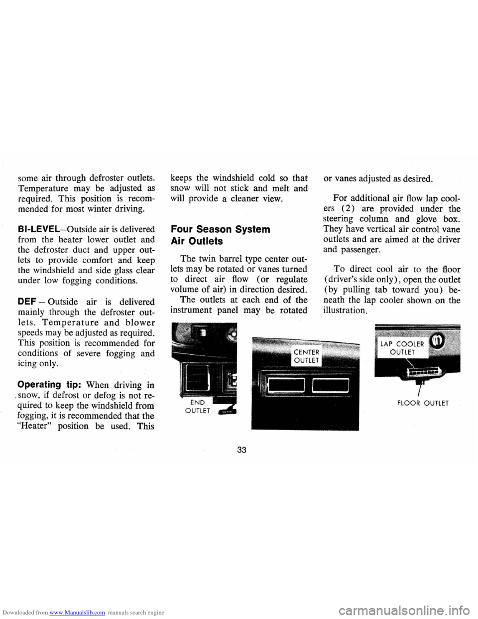
The twin barrel type center out
lets may be rotated or vanes turned
to direct air flow ( or regulate
volume of air) in direction desired.
The outlets at each end of the
instrument panel may be rotated
33
or vanes adjusted as desired.
For additional air flow lap cool
ers
(2) are provided under the
steering column and glove box.
They have vertical air control vane
outlets and are aimed at the driver
and passenger.
To direct cool air to the floor
(driver's side only), open the outlet
(by pulling tab toward you) be
neath the lap cooler shown on the
illustration.
FLOOR OUTLET
Page 52 of 85
Downloaded from www.Manualslib.com manuals search engine Checking Oil Level
The engine oil should be main
tained at proper level. The best
time to check it
is before operating
the engine or
as the last step in a
fuel stop. This will allow the oil ac
cumulation in the engine to drain
back in the crankcase.
To check
the level, remove the oil guage rod
(dip stick), wipe it clean and rein
sert
it firmly for an accurate read
ing. The oil gauge rod
is marked
"FULL" and "ADD." The oil level
should be maintained in the safety
margin, neither going above the
"FULL" line nor below the "ADD"
line. Reseat the gauge firmly after
taking the reading.
Supplemental Engine Oil
Additives
The regular use of supplemental
additives
is specifically not recom
mended and will increase operat
ing costs. However, supplemental additives
are available that can
effectively and economically solve
certain specific problems without
causing other difficulties.
For ex
ample, if higher detergency
is re
quired to reduce varnish and
sludge deposits resulting from
some unusual operational diffi
culty, a thoroughly tested and ap
proved additive -
"Super Engine
Oil Supplement" -is available at
your Chevrolet dealer.
In the event
of an operational problem, consult
your dealer for advice before
us
ing supplemental additives.
Drive Belts
Every 6,000 miles or 4 months
inspect drive belts for wear , fray
ing, cracking , and tension. Belts
which are in poor condition should
be replaced immediately.
Check tension by applying mod
erate thumb pressure midway be
tween pulleys.
If the center-to-
49
center distance between pulleys is
13 to 16 inches, the belt should
deflect
1;2 inch . If the center-to
center distance
is 7 to 10 inches,
the belt should deflect
1;4 inch.
Loose belts should be retensioned
to give the correct deflection.
It is recommended that belts be
replaced every 24 months or
24,000
miles , whichever occurs first.
Air Cleaner
CAUTIOH:Donot remo.vElfhe f1ngl,,~ al,. cleaner unlesstempo,ary removall$.nec~ essarrdur;ng repair ormaintenal1ce ot the vehicle; When t"ealrC/f1aneri$/~emoved backtlringcan cause tire in the engine
compartment. .',' . '
Flame Arrester -Every 12,000
miles-Clean the arrester (located
in the base of the air cleaner) with
kerosene or a suitable solvent. Dry
with compressed air.
Rear Axle
Standard -Every 4 months or
6,000 miles, whichever occurs
Page 56 of 85
Downloaded from www.Manualslib.com manuals search engine "HOT" MARK
"COLD" MARK
>-f.. __ "AOO"
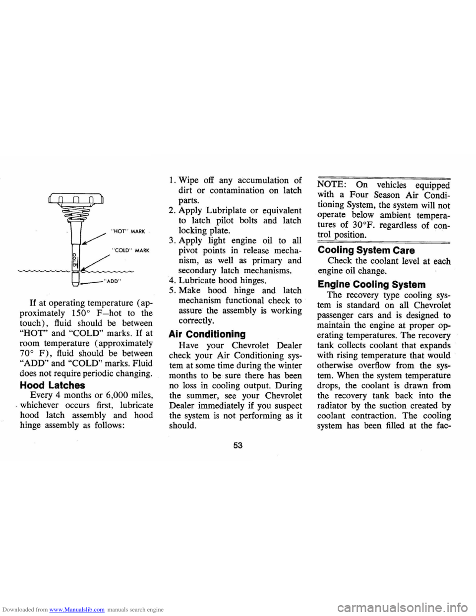
If at operating temperature (ap
proximately
150° F-hot to the
touch), fluid should be between
"HOT" and "COLD" marks. If at
room temperature (approximately
70° F), fluid should be between
"ADD" and "COLD" marks. Fluid
does not require periodic changing.
Hood Latches
Every 4 months or 6,000 miles,
. whichever occurs first, lubricate
hood latch assembly and hood
hinge assembly
as follows:
1. Wipe off any accumulation of
dirt or contamination on latch
parts.
2. Apply Lubriplate or equivalent
to latch pilot bolts and latch
locking plate.
3. Apply light engine oil to all
pivot points in release mecha
nism,
as well as primary and
secondary latch mechanisms.
4. Lubricate hood hinges.
5. Make hood hinge and latch
mechanism functional check to
assure the assembly
is working
correctly.
Air Conditioning
Have your Chevrolet Dealer
check your Air Conditioning
sys
tem at some time during the winter
months to
be sure there has been
no loss in cooling output. During
the summer,
see your Chevrolet
Dealer immediately if you suspect
the system
is not performing as it
should.
53
NOTE: On vehicles equipped
with a Four Season Air Condi
tioning System, the system will not
operate below ambient tempera
tures of
30°F. regardless of con
trol position.
Cooling System Care
Check the coolant level at each
engine · oil change.
Engine Cooling System
The recovery type cooling sys
tem is standard on all Chevrolet
passenger cars and
is designed to
maintain the engine at proper op
erating temperatures.
The recovery
tank collects coolant that expands
with rising temperature that would
otherwise overflow from the
sys
tem. When · the system temperature
drops, the coolant
is drawn from
the recovery tank back into the
radiator by the suction created by
coolant contraction. The cooling
system has been filled at the fac-
Page 57 of 85
Downloaded from www.Manualslib.com manuals search engine tory with a high-quality, inhibited,
year-around coolant that meets the
standards of General Motors
Spe
cification 1899-M. This coolant
solution provides freezing protec
tion to
-20oP (-35°P in Can
ada), and it has been formulated to
be used for two full calendar years
or
24,000 miles, whichever first
occurs, of normal operation with
out replacement, provided the
proper concentration of coolant is
maintained.
Cooling System Care
The radiator cap should not be
removed to check coolant level.
Check the coolant level visually in
the 'see thru' coolant recovery tank
at least
as frequently as engine oil
changes. Level should be at the
"full cold" mark on the recovery
tank when the system
is cold. At
normal operating temperature the
coolant should be at the
"full hot"
mark on the recovery tank. Add sufficient
coolant to the recovery
tank.
Use a 50/50 mixture of high
quality ethylene glycol antifreeze
and water for coolant additions.
If
regular additions are required, see
your dealer for a cooling system
check.
NOTE: If recommended quality
antifreeze
is used, supplemental in
hibitors or additives claiming to
provide increased capability are
not necessary. They may be detri
mental to the efficient operation of
the system, and represent an un
necessary operating expense.
Every year, the cooling system
should be serviced
as follows:
1. Wash
radiator cap and filler
neck with clean water.
2. Check coolant for proper level
and freeze protection.
3. Pressure test system and radia-
54
tor cap for proper pressure hold
ing capacity (15 psi) .
If re
placement of cap
is required, use
the special AC cap designed for
coolant recovery systems, speci
fied for your model.
4. Tighten hose clamps and inspect
all hoses. Replace hoses when
ever swollen, checked or other
wise deteriorated.
5. Clean frontal area of radiator
core and air conditioning con
denser.
Replace hoses every 24 months
or 24,000 miles or earlier if
checked, swollen or otherwise de
teriorated. Every two years
or 24,-
000 miles, whichever first occurs,
the cooling system should be
flushed and refilled using the fol
lowing recommended procedure:
1. Remove radiator cap when
engine is cool by:
• Slowly rotating cap counter-
Page 64 of 85
Downloaded from www.Manualslib.com manuals search engine Warranty
Tires are warranted by the tire
manufacturers as covered in the
New Vehicle Warranty and
Policy
on Owner Service folder furnished
with your vehicle. However, for
the added convenience of owners,
many Chevrolet dealers are
equipped to handle tire warranty
adjustments
on certain makes of
tires provided
on 1974 Chevrolet
cars.
Tire Traction
A decrease in driving, corner
ing, and braking traction occurs
when water, snow, ice, gravel,
or
other material is on the road sur
face. Driving practices and
car
speed should be adjusted to the
road conditions.
When driving
on wet or slushy
roads, it is possible for a wedge of
water to build up between the tire and
road surface. This phenom
enon, known
as hydroplaning,
may cause partial
or complete loss
of traction, which adversely affects
vehicle control and stopping abil
ity.
To reduce the possiblity of
traction loss, the following precau
tions should be observed:
1. Slow down during rainstorms or
when roads are slushy.
2. Slow down if road has standing
water
or puddles.
3. Replace tires when tread wear
indicators are visible.
4. Keep tires properly inflated.
For temporary assistance when
traction
is lost on ice or snow, the
use of
AC Liquid Tire Chain is
recommended.
REMINDER: Cars equipped with
front disc brakes have a built-in
61
wear indicator that is designed to
make a high frequency, squealing
or cricket-like warning sound when
the linings are worn to where re
placement
is required. The sound
will occur intermittently
or con
tinuously when wheels are rolling,
but will disappear when the brake
pedal
is applied firmly. See also the
various brake checks listed in the
Chevrolet maintenance schedule
folder.
Space Saver Spare Tire
The Space Saver Spare tire is
designed for emergency purposes
only. Continuous use
or operation
at speeds in excess of
50 mph is not
recommended. The Space Saver
Spare tire warranty
is void if any
inflation device containing sealants
is used. Approved inflation gases
are air, carbon dioxide, nitrogen,
and Freon 22.
Page 70 of 85
Downloaded from www.Manualslib.com manuals search engine The chart on the previous page, and the information on the pages which follow, contains information designed to aid the average driver to discover, and possibly correct, conditions resulting in minor
mechanical difficulties in his car. The chart, designed to point out
possible solutions to several of the most common automotive malfunctions and point out a logical checking sequence, will lead step by step to the most likely causes and corrective procedures. If, after making the checks and adjustments suggested, the source of the trouble has not been found and corrected, it is strongly recom
mended that an Authorized Chevrolet Dealer insp~ct the vehicle and make whatever repairs or adjustments are necessary.
;iA~>~I/~,~.#Y'T~~hiri~~:e~It.;ne;CC2i'~6p'4~cl~.;.'Ii~;~;,;(i '~i.. . .....•.. l'for",;tlgC;(lnY;tlspec';o~;1J1 ainfenCJn.c:~ ..
If the ignition switch will cause the engine to "turn over" or "crank" but the car will not start, check Steps A through 0 below. NOTE : If continual "flooding" of the carburetor is evidenced by a carburetor wet with
fuel or black exhaust smoke,
perform the operation sug
gested in paragraph D only .
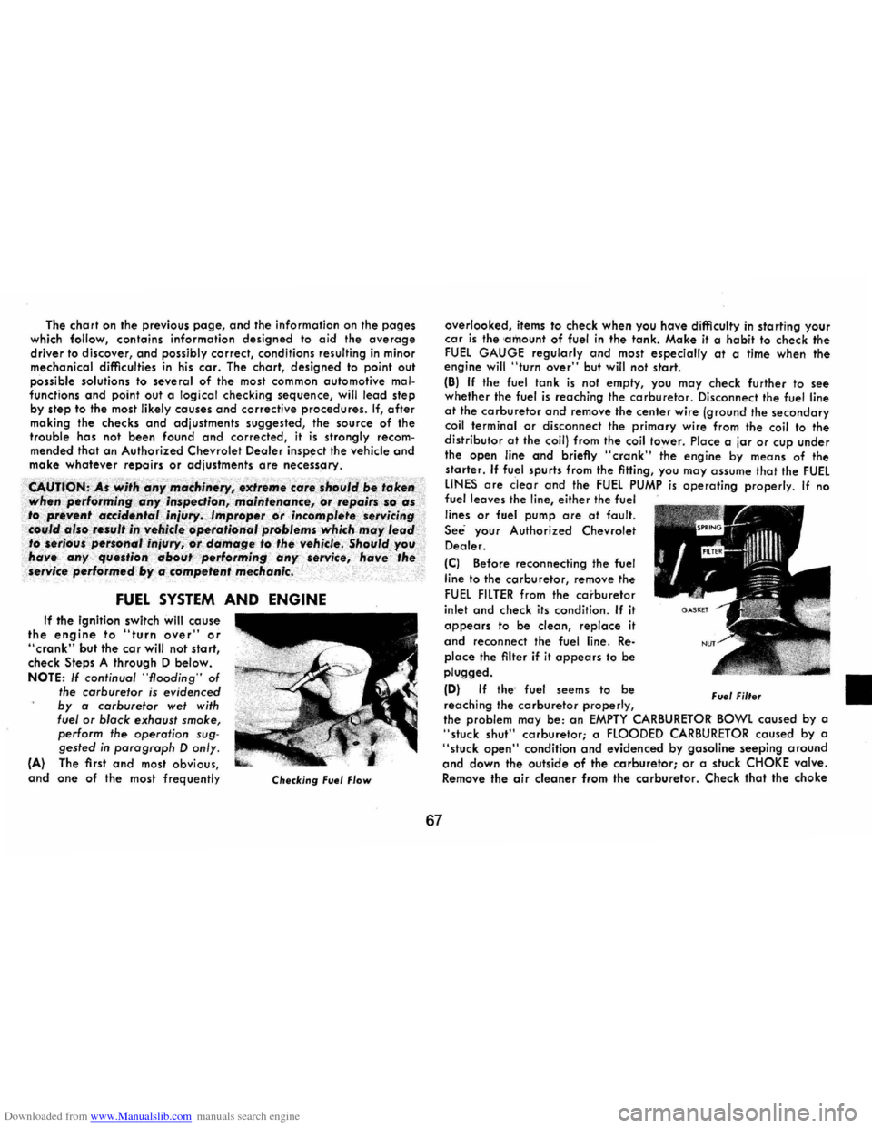
(A) The first and most obvious, and one of the most frequently Checking Fuel Flow
67
overlooked, items to check when you have difficulty in starting your car is the 'amount of fuel in the tank. Make it a habit to check the FUEL GAUGE regularly and most especially at a time when the engine will "turn over" but will not start.
(B) If the fuel tank is not empty, you may check further to see whether the fuel is reaching the carburetor. Disconnect the fuel line at the carburetor and remove the center wire (ground the secondary coil terminal or disconnect the primary wire from the coil to the
distributor at the coil) from the coil tower. Place a jar or cup under the open line and briefly "crank" the engine by means of the starter. If fuel spurts from the fitting, you may assume that the FUEL LINES are clear and the FUEL PUMP is operating properly. If no fuel leaves the line, either the fuel
lines or fuel pump are at fault ,
See your Authorized Chevrolet
Dealer.
(C) Before reconnecting the fuel
line
to the carburetor, remove the
FUEL FILTER from the carbu retor
inlet and check its condition . If it
appears to be clean, replace it
and reconnect the fuel line. Re
place the filter if it appears to be plugged.
(0) If the' fuel seems to be
reaching the carburetor properly, Fuel Filter
the problem may be: an EMPTY CARBURETOR BOWL caused by a "stuck shut" carburetor; a FLOODED CARBURETOR caused by a "stuck open" condition and evidenced by gasoline seeping around and down the outside of the carburetor; or a stuck CHOKE valve. Remove the air cleaner from the carburetor. Check that the choke
•
Page 74 of 85
Downloaded from www.Manualslib.com manuals search engine SPECIFICATIONS (Cont'd)
Cooling System: 250 L-6 350 V-8
U.S. Measure (qts.)
12.5 15.5"
Imperial Measure (qts.)
10.5 13·
·with air condo add 1 qt. U.S. measure (3A qt. ,Imperial meas.)
Thermostat
All engines (Exc. RPO L-82, Z28) .................. 1950
RPO L-82, Z28 ................... ~ . . ..... 1800
Radiator Pressure Cap ......................... 15 lb.
71
Air Conditioning System
Compressor oil (525 vis.) ....................... 11 oz.
Refrigerant-R-1 2
Four
Seasons. . . . . . . . . . . . . . . . . . . . . . . .. 3 lb. 12 oz.
Turbo Hydramatic U.S. Measure
350............. ....................... 10.0 qts. 400. . . . . . . . . . . . . . . . . . . . . . . . . . . . . . . . . . . . . 11.0 qts.
TURN SIGNAL FLASHER:
Imperial Measure 8.25 qts. 9.25 qts.
Type .................................... Capacity
All .................................. 2 lamp (LL)
Hazard Warning Flasher, All .................. 4 lamp
TIRE INFORMATION:
Complete tire information will be found on pages 56, 57, 58, 59,60,61,62 and 63.
I
Page 76 of 85
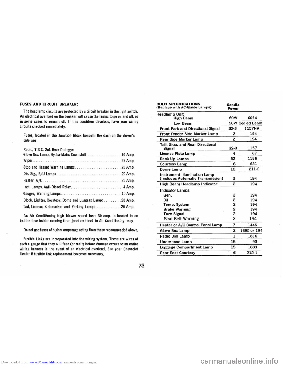
Downloaded from www.Manualslib.com manuals search engine FUSES AND CIRCUIT BREAKER:
The head lamp circuit s are protected by a circuit breaker in the light switch.
An electrical overload on the breaker will cause the lamps to go on and off, or
in some cases to remain off. If this condition develops, have your wiring circuits checked immediately.
Fuses, located in the Junction Block beneath the dash on the driver's side are:
Radio, T.S.C. Sol. Rear Defogger Glove Box Lamp, Hydra·Matic Downshift ...
Wiper ..
.10 Amp.
... 25 Amp.
Stop and Hazard Warning Lamps. . . . . . ... . ........ 20 Amp.
Dir. Sig., B/U Lamps........... ............. ... .. . ... 20 Amp.
Heater, A /C .... . .25 Amp.
Inst. Lamps, Anti-Diesel Relay............. ....... . .. 4 Amp.
Gauges, Warning Lamps ......................... 10 Amp.
Clock, Lighter, Courtesy, Dome and Luggage Lamps. . .20 Amp.
Taii, License, Sidemarker and Parking Lamps ... ..... 20 Amp.
An Air Conditioning high blower speed fuse, 30 amp. is located in an
In-line fuse holder running from junction block to Air Conditioning relay.
Do not use fuses of higher amperage rating than those recommended above.
Fusible Links are incorporated into the wiring system. These are wires of such a gauge that they will fuse (or melt) before damage occurs to an entire
wiring harness in the event of an electrical overload. See your Chevrolet Dealer if fusible link replacement becomes necessary.
73
BULB SPECIFICATIONS (Replace with AC·Guide Lamps)
Headlamp Unit High Beam
low Beam
Front Park
and Directional Signal
Front Fender Side Marker lamp
Rear Side Marker lamp
Tail, Stop, and Rear Directional Signal
license Plate lamp
Back Up lamps
Courtesy lamp
Dome Lamp
Instrument Illumination lamp (Includes Automatic Transmission)
High Beam
Headlamp Indicator
Indicator lamps Gen. Oil Temp. System
Brake Warning
Turn Signal Seat Belt Warning
Heater or AIC Control Panel lamp
Glove Box lamp
Radio Dial lamp
Underhood lamp
luggage Compartment lamp
Rear Seat Courtesy
Candle
Power
60W 6014
50W Sealed Beam
32·3 1157NA
? 194
2 194
32·3 1157
4 67
32 1156
6 631
12 211·2
2 194
2 194
2 194 2 194 2 194 2 194 2 194 2 194
7 1445
2 1895 or 194
1 1816
15 93
15 1003
6 212-1
Page 81 of 85
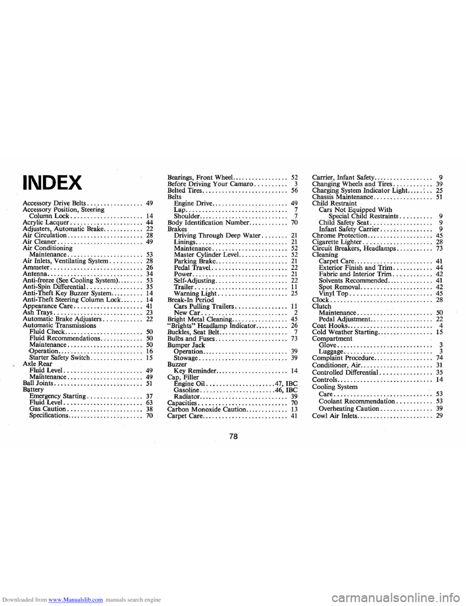
Downloaded from www.Manualslib.com manuals search engine INDEX
Accessory Drive Belts. . . . . . . . . . . . . . . .. 49 Accessory Position, Steering
Column Lock. . . . . . . . . . . . . . . . . . . . .. 14 Acrylic Lacquer ...................... 44 Adjusters, Automatic Brake. . . . . . . . . . .. 22 Air Circulation. . . . . . . . . . . . . . . . . . . . . .. 28 Air Cleaner. . . . . . . . . . . . . . . . . . . . . . . . .. 49 Air Conditioning
Maintenance. . . . . . . . . . . . . . . . . . . . . .. 53 Air Inlets, Ventilating System. . . . . . . . .. 28 Ammeter ............................ 26
Antenna ............................. 34 Anti-freeze (See Cooling System) ........ 53 Anti-Spin Differential. . . . . . . . . . . . . . . .. 35 Anti-Theft Key Buzzer System .......... 14 Anti-Theft Steering Column Lock ....... 14 Appearance Care ..................... 41 Ash Trays. . . . . . . . . . . . . . . . . . . . . . . . . .. 23 Automatic Brake Adjusters. . . . . . . . . . .. 22 Automatic Transmissions
Fluid Check ........................ 50 Fluid Recommendations ............. 50 Maintenance. . . . . . . . . . . . . . . . . . . . . .. 50 -Operation ...... _ ... _ ...... _ ........ 16 Starter Safety Switch _ . . . . . . . . . . . . . .. 15 Axle Rear Flu!? Level. ....................... 49 Mamtenance. . . . . . . . . . . . . . . . . . . . . .. 49 Ball Joints. . . . . . . . . . . . . . . . . . . . . . . . . .. 51 Battery
Emergency Starting ................. 37 Fluid Level. . . . . . . . . . . . . . . . . . . . . . .. 63 Gas Caution. . . . . . . . . . . . . . . . . . . . . .. 38 Specifications. . . . . . . . . . . . . . . . . . . . . .. 70
Bearings, Front Wheel. . . . . . . . . . . . . . . .. 52 Before Driving Your Camaro.......... 3
Belted Tires. . . . . . . . . . . . . . . . . . . . . . . . .. 56 Belts
Engine Drive. . . . . . . . . . . . . . . . . . . . . .. 49 Lap ............................... 7 Shoulder........................... 7
Body Identification Number ............ 70 Brakes
D.riying Through Deep Water. . . . . . .. 21 Lmmgs ............................ 21 Maintenance. . . . . . . . . . . . . . . . . . . . . .. 52 Master Cylinder Level. .............. 52 Parking Brake. . . . . . . . . . . . . . . . . . . . .. 21 Pedal Travel ....................... 22
Power. ............................ 21 Self-Adjusting. . . . . . . . . . . . . . . . . . . . .. 22
Trailer ............................ 11 Warning Light. .................... 25 Break-In Period
Cars Pulling Trailers. . . . . . . . . . . . . . .. 11 New Car .......................... 2
Bright Metal Cleaning ................. 45 "Brights" Headlamp Indicator .......... 26 Buckles, Seat Belt. . . . . . . . . . . . . . . . . . . . . 7
Bulbs and Fuses. . . . . . . . . . . . . . . . . . . . . . 73 Bumper Jack
Operation.. . . . . . . . . . . . . . . . . . . . . . . .. 39 Stowage ........................... 39 Buzzer
Key Reminder. . . . . . . . . . . . . . .. . . . . .. 14 Cap, Filler
Engine Oil. ................... .47, IBC
Gasoline ....................... 46, IBC
Radiator. . . . . . . . . . . . . . . . . . . . . . . . . .. 39 Capacities. . . . . . . . . . . . . . . . . . . . . . . . . .. 70 Carbon Monoxide Caution.. . . . . . . . . . .. 13 Carpet Care .......................... 41
78
Carrier, Infant Safety.... . . . . . . . . . . . . .. 9
Changing Wheels and Tires. . . . . . . . . . .. 39 Charging System Indicator Light. .... : .. 25 Chassis Maintenance. . . . . . . . . . . . . . . . .. 51 Child Restraint
Cars Not Equipped With Special Child Restraints. . . . . . . . .. 9
Child Safety Seat. . . . . . . . . . . . . . . . . .. 9
Infant Safety Carrier .... ; . . . . . . . . . .. 9
Chrome Protection .................... 45 Cigarette Lighter ..................... 28 Circuit Breakers, Headlamps. . . . . . . . . .. 73 Cleaning
Carpet Care. . . . . . . . . . . . . . . . . . . . . . .. 41 Exterior Finish and Trim. . . . . . . . . . .. 44
Fabric and Interior Trim. . . . . . . . . . .. 42
Solvents Recommended .......... , ... 41 Spot Removal. . . . . . . . . . . . . . . . . . . . .. 42
Vinyl Top. . . . . . . . . . . . . . . . . . . . . . . .. 45 Clock ............................... 28 Clutch Maintenance. . . . . . . . . . . . . . . . . . . . . .. 50 Pedal Adjustment. . . . . . . . . . . . . . . . . .. 22 Coat Hooks. . . . . . . . . . . . . . . . . . . . . . . . .. 4
Cold Weather Starting ................. 15 Compartment Glove............................. 3 Luggage........................... 3
Complaint Procedure .................. 74 Conditioner, Air ...................... 31 Controlled Differential. . . . . . . . . . . . . . .. 35 Controls ............................. 14 Cooling System Care .............................. 53 Coolant Recommendation. . . . . . . . . .. 53 Overheating Caution. . . . . . . . . . . . . . .. 39 Cowl Air Inlets ....................... 29