wheel CHEVROLET CAMARO 1974 2.G Owners Manual
[x] Cancel search | Manufacturer: CHEVROLET, Model Year: 1974, Model line: CAMARO, Model: CHEVROLET CAMARO 1974 2.GPages: 85, PDF Size: 32.84 MB
Page 15 of 85
Downloaded from www.Manualslib.com manuals search engine Break-in Schedule
In addition to the new car
break-in instructions in this man
ual, it
is recommended that your
new Camaro be operated for
500
miles before trailer towing. If it is
necessary to tow during this period,
avoid speeds over
50 MPH and full throttle
starts. The same precau
tions should be observed whenever
a new engine, transmission
or axle
is installed in your car.
Operation in Foreign Countries
Your Camaro is designed to op
erate on fuel of approximately
91
research octane number or higher,
sold in the United States and Can
ada.
If you plan to operate your
Camaro outside the continental
limits of the United States
or Can
ada, there
is a possibility that the
best fuels available in some coun
tries are so low in anti-knock
quality that excessive knocking
and serious engine damage may
. result from their use. To obtain
information on the quality of fuels available
in the countries in which
you plan to travel , write to Chevro
let Motor Division, Service Depart
ment, Detroit, Michigan
48202,
(or in Canada write to General
Motors of Canada Limited,
Owner
Relations Department , Oshawa,
Ontario),
giving:
• The vehicle identification num
ber ( on plate on instrument
panel ahead of the steering
wheel and visible through the
windshield , or from registration
slip or title).
• The country or countries in
12
which you plan to travel.
It
is recommended that you not
operate your Camaro in any coun
try not having fuels meeting the
requirements of
your Camaro
engine. Engine modifications are
not available to compensate for
low anti-knock quality fuels. Op
eration of your car under condi
tions of continuous
or excessive
knocking constitutes misuse of the
engine and may cause engine dam
age for which the Chevrolet Divi
sion
is not responsible under the
terms
of the Chevrolet New
Vehicle Warranty.
Page 17 of 85
Downloaded from www.Manualslib.com manuals search engine STEERING COLUMN CONTROLS
Anti-Theft Steering
Column Lock
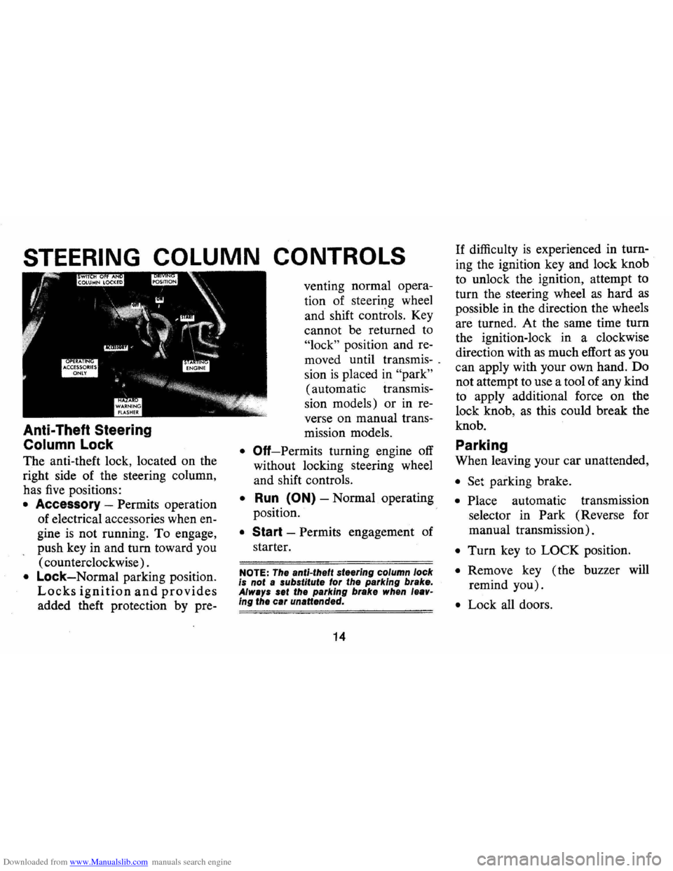
The anti-theft lock, located on the
right side of the steering column,
has
five positions:
• Accessory -Permits operation
of electrical accessories when en
gine
is not running. To engage,
push key in and turn toward you
( counterclockwise) .
• Lock-Normal parking position.
Locks ignition and provides
added theft protection by pre- venting
normal opera
tion of steering wheel
and shift controls. Key
cannot be returned to
"lock" position and re
moved until transmis-.
sion
is placed in "park"
(automatic transmis
sion models) or in re
verse on manual trans-
mission models.
• Off-Permits turning engine off
without locking steering wheel
and shift controls.
• Run (ON) -Normal operating
position.
• Start -Permits engagement of
starter.
NOTE: The anti-theft steering column lock
is not a substitute for the parking brake.
Always set the parking brake when leav
ing the car unattended.
14
If difficulty is experienced in turn
ing the ignition key and lock knob
to unlock the ignition, attempt to
turn the steering wheel
as hard as
possible in the direction the wheels
are turned. At the same time turn
the ignition-lock in a clockwise
direction with
as much effort as you
can apply with your own hand. Do
not attempt to use a tool of any kind
to apply additional force on the
lock knob,
as this could break the
knob.
Parking
When leaving your car unattended,
• Set parking brake.
• Place automatic transmission
selector in Park (Reverse for
manual transmission).
• Turn key to LOCK position.
• Remove key ( the buzzer will
remind you).
• Lock all doors.
Page 21 of 85
Downloaded from www.Manualslib.com manuals search engine Driving with Manual Transmissions
The 3-and 4-speed transmission
shift levers, extending from the
fioor, have their special shift pat
tern diagram located on the knob.
Depress the clutch pedal fully be
fore attempting to shift
toa differ
ent gear, then release the pedal to
move in that gear.
For normal
accelerations shift into second gear
at
20 mph; into third gear at 30
mph; and on 4-speed models into
fourth gear at
40 mph.
Both transmissions, being fully
synchronized, may be downshifted
into 1 st gear at any speed below
20
m. p.h. Shift into Reverse gear only
after the car has stopped. Always
depress and release the clutch pedal
fully when shifting.
Also, shift into
"Reverse" before
shutting
off engine. This will permit the
ignition key to be turned to the
"Lock" position.
Good Driving Practice: On cars
equipped with manual transmis
sions , use second gear at slow
speeds (less than
30 m.p.h.) when
driving in stop-and-go traffic; for
improved vehicle performance dur
ing acceleration; and when de
scending steep hills.
18
Turn Signals and Lane
Change Feature
The tum signal lever is located
on the left side of the steering col
umn immediately under the steer
ing wheel. The lever
is moved up
,ward to signal a right
tum and
downward to signal a left
tum.
Lamps on the front and rear of the
car transmit this signal to other
motorists and pedestrians. The
ig
nition switch must be in the "ON"
position in order for the tum sig
nals to be operational. This feature
prevents battery drain if the lever .
is left in an "ON" position when
your car
is not in use.
Page 22 of 85
Downloaded from www.Manualslib.com manuals search engine In a normal turning situation
such
as turning a corner, the turn
signal
is cancelled automatically
after the turn
is completed. How
ever, in some driving maneuvers
such
as changing lanes on an ex
pressway, the steering wheel
is not
turned back sufficiently after com
pleting the turn to automatically
cancel the turn signal. For con
venience in such maneuvers, the
driver can flash the turn signals by
moving the turn signal lever part
way (to the first stop) and holding
it there. The lever returns to the
neutral or cancelled position when
the driver releases his hold on the
lever.
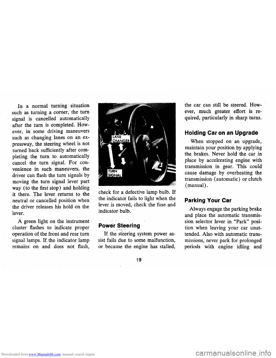
A green light on the instrument
cluster flashes to indicate proper
operation of the
front and rear tum
> signal lamps. If the indicator lamp
remains on and does not flash, check
for a defective lamp bulb.
If
the indicator fails to light when the
lever
is moved, check the fuse and
indicator bulb.
Powe'r Steering
If
the'-~[~~ring system power as
sist fails due to some malfunction,
or because the engine has stalled,
19
the car can still be steered. How
ever, much greater effort
is re
quired, particularly in sharp turns.
Holding Car on an Upgrade
When stopped on an upgrade,
maintain your position by applying
the brakes. Never hold the car in
place by accelerating engine with
transmission in gear. This could
cause damage by overheating the
transmission (automatic) or clutch
(manual).
Parking Your Car
Always engage the parking brake
and place the automatic transmis
sion selector lever in
"Park" posi
tion when leaving your car unat
tended. Also with automatic trans
missions, never park for prolonged
periods with engine idling and
Page 23 of 85
Downloaded from www.Manualslib.com manuals search engine transmiSSIOn in gear, especially if
your car
is equipped with air con
ditioning. This practice
is detri
mental to the transmission, due to
overheating.
Tilt Steering Wheel
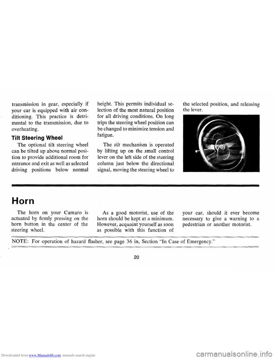
The optional tilt steering wheel
can be tilted up above normal posi
tion to provide additional room for
entrance and exit
as well as selected
driving positions below normal
Horn
The horn on your Camara is
actuated by firmly pressing on the
horn button in the center of the
steering wheel. height.
This permits individual
se
lection of the most natural position
for all driving conditions.
On long
trips
the steering wheel position can
be changed to minimi ze tension and
fatigue.
The
tilt mechanism is operated
by lifting up on the .small control
lever on the left side of the
steering
column just below the directional
signal, moving the steering wheel to
As a good motorist , use of the
horn should be kept at a minimum.
However , acquaint yourself
as soon
as possible with this function of the
selected position, and releasing
the lever.
your car, should it ever become
necessary to give a warning
to a
pedestrian or another motorist.
NOTE: For operation of hazard flasher, see page 36 in, Section "In Case of Emergency. "
20
Page 25 of 85
Downloaded from www.Manualslib.com manuals search engine REMINDER: Cars equipped with
front disc brakes have a built-in
wear indicator that
is designed to
make a high frequency, squealing,
or cricket-like warning sound when
the linings are worn to where re
placement
is required. The sound
will occur intermittently or con
tinuously when wheels are rolling,
but will change or cease completely
when the brake pedal
is applied
firmly.
See also the various brake
checks listed in the Chevrolet main
tenance schedule folder.
Automatic Brake Adjusters
• Brakes on this car (except for
the parking brake) are self
adjusting, designed to eliminate
periodic brake adjustments .
• Drum brake adjustment is made
automatically
as the brakes are
applied while car
is moving
backwards .
• Disc brake adjustment is made
automatically with each brake
application.
• If excess brake pedal travel de
velops, drive alternately back
ward and forward several times
and apply brakes firmly in each
direction.
• See your dealer if normal pedal
travel
is not restored, or if there
is a rapid increase in pedal travel,
which could be a sign of other
brake
trOUble.
Clutch Adjustment
Clutch adjustment should be
checked and adjusted periodically
as necessary to compensate for
22
clutch facing wear. To check, de
press pedal by hand until resistance
is felt. Free travel of pedal should
be approximately one inch; if very
little or no free travel
is evident,
clutch adjustment
is required.
Headlight Beam Switch
"High" and "low" headlight
beams are controlled by the floor
button at your left foot. The indi
cator, located in the speedometer
dial, will light up when the high
beams are in use.
Page 38 of 85
Downloaded from www.Manualslib.com manuals search engine OTHER CONTROLS AND FEATURES
Positraction Rear Axle
The optional Positraction pro
vides additional traction on snow ,
ice , mud, sand, and gravel, par
ticularly when one rear wheel
is on
a surface providing poor traction.
During normal driving and cor
nering, the Positraction unit
func~
tions as a standard differential.
When one wheel encounters a slip
pery surface, however , the Positrac
tion directs driving force to the rear
wheel having the better traction.
Power Windows
Power windows have an ignition
interlock so the windows cannot be
operated unless the ignition switch
is in the "on" position.
REMINDER: Remove the ignition
key when the vehicle
is not at
tended by a responsible person.
A master control for both win
dows
is provided at the driver's
position. Also, an individual switch
is provided under right window for
passenger use.
Adjustable Front Seat Back
-Driver's Side
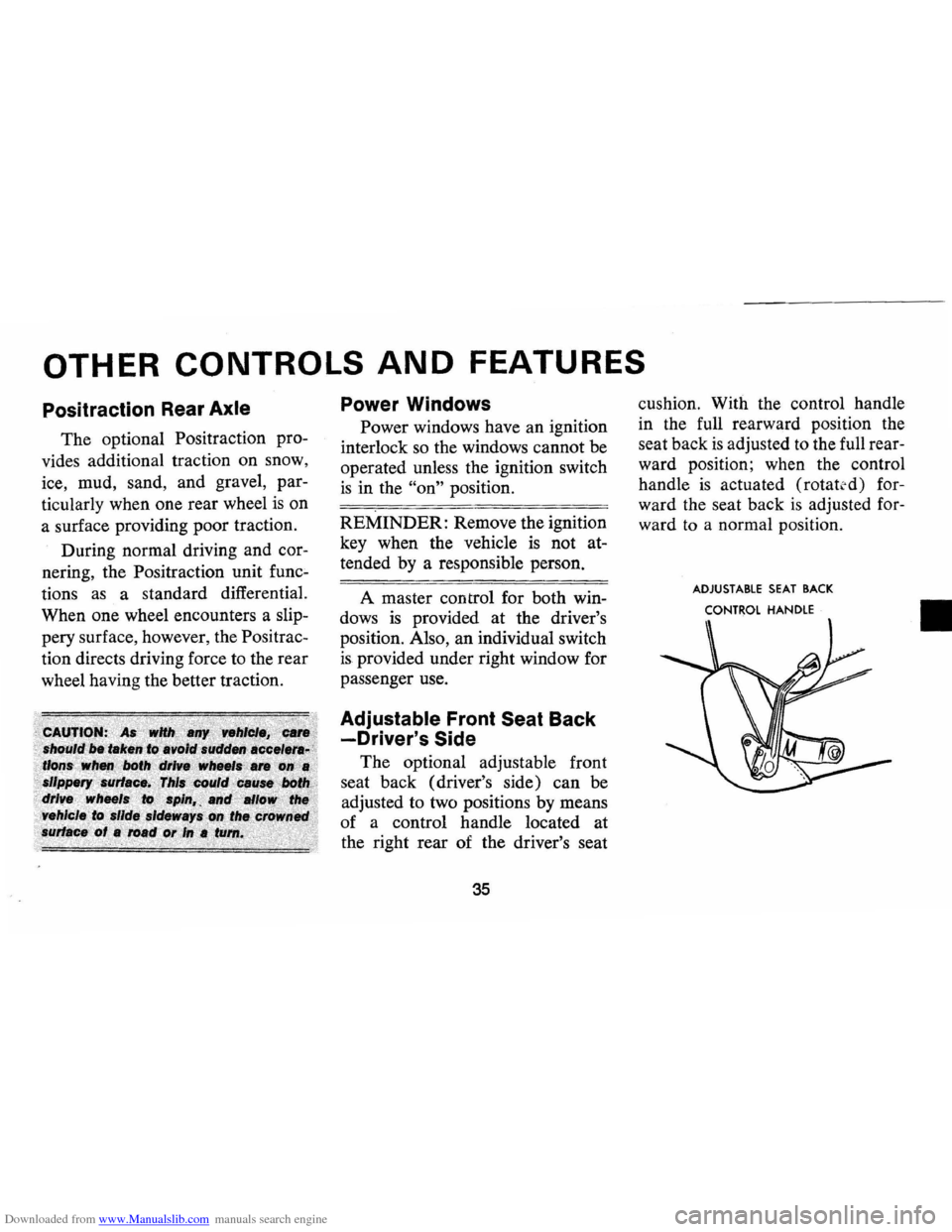
The optional adjustable front
seat back (driver's side) can be
adjusted to two positions by means
of a control handle located at
the right rear of the driver's seat
35
cushion. With the control handle
in the full rearward position the
seat back
is adjusted to the full rear
ward position; when the control
handle
is actuated (rotat td) for
ward the seat back
is adjusted for
ward
to a normal position .
ADJUSTABLE SEAT BACK
CONTROL
HANDLE
II
Page 39 of 85
Downloaded from www.Manualslib.com manuals search engine I n Case of Emergency
Four-Way Hazard
Warning
Flasher
• Use the warning flasher to warn
other drivers any time your
vehicle becomes a traffic hazard,
day
or night.
• Avoid stopping on the roadway
if possible.
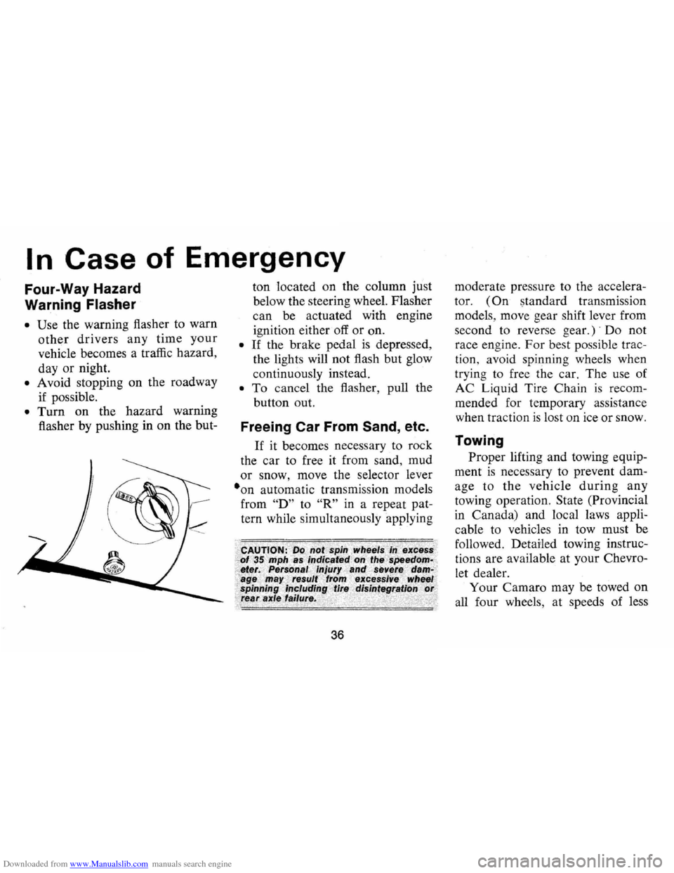
• Turn on the hazard warning
flasher by pushing in on the but- ton
located on the column just
below the steering wheel. Flasher
can be actuated with engine
ignition either off
or on.
• If the brake pedal is depressed,
the lights will not flash but glow
continuously instead.
• To cancel the flasher, pull the
button out.
Freeing Car From Sand, etc.
If it becomes necessary to rock
the car to free it from sand, mud
or snow, move the selector lever
·on automatic transmission models
from
"D" to "R" in a repeat pat
tern while simultaneously applying
36
moderate pressure to the accelera
tor.
(On standard transmission
models, move gear shift lever from
second to reverse
gear.)' Do not
race engine.
For best possible trac
tion, avoid spinning wheels when
trying to free the car. The use of
AC Liquid Tire Chain
is recom
mended for temporary assistance
when traction
is lost on ice or snow.
Towing
Proper lifting and towing equip
ment
is necessary to prevent dam
age to
the vehicle during any
towing operation. State (Provincial
in Canada) and local laws appli
cable to vehicles in tow must be
followed. Detailed towing instruc
tions are available at your Chevro
let dealer.
Your Camaro may be towed on
all four wheels, at speeds of less
Page 42 of 85
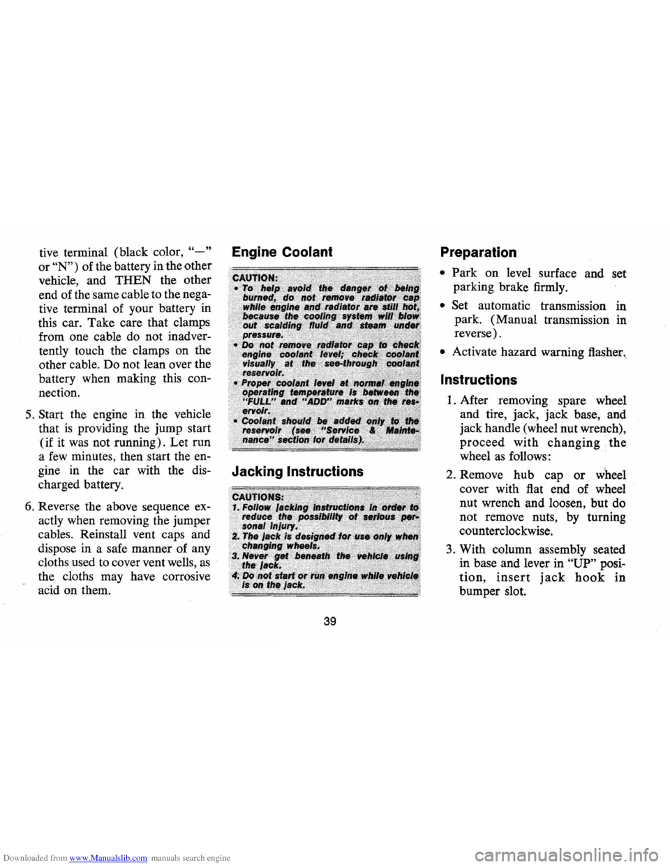
Downloaded from www.Manualslib.com manuals search engine tive terminal (black color, "-" Engine Coolant
or "N") of the battery in the other
vehicle, and
THEN the other
end of the same cable to the nega
tive terminal of your battery in
this car. Take care that clamps
from one cable do not inadver
tently touch the clamps on the
other cable. Do not lean over the
battery when making this con
nection.
5. Start the engine in the vehicle
that
is providing the jump start
(if it
was not running). Let run
a
few minutes, then start the en-
gine in the car with the dis-
Jacking Instructions
charged battery.
6. Reverse the above sequence ex
actly when removing the jumper
cables. Reinstall vent caps and
dispose in a safe manner of any
cloths used to cover vent wells,
as
the cloths may have corrosive
acid on them.
39
Preparation
• Park on level surface and set
parking brake firmly.
• Set automatic transmission in
park. (Manual transmission in
reverse).
• Activate hazard warning flasher.
Instructions
1. After removing spare wheel
and tire, jack, jack
base,and
jack handle (wheel nut wrench),
proceed with changing the
wheel
as follows:
2. Remove hub cap
or wheel
cover with flat end of wheel
nut wrench and loosen, but do
not remove nuts, by turning
counterclockwise.
3. With column assembly seated
in base and lever in
"UP" posi
tion,
insert jack hook in
bumper slot.
Page 43 of 85
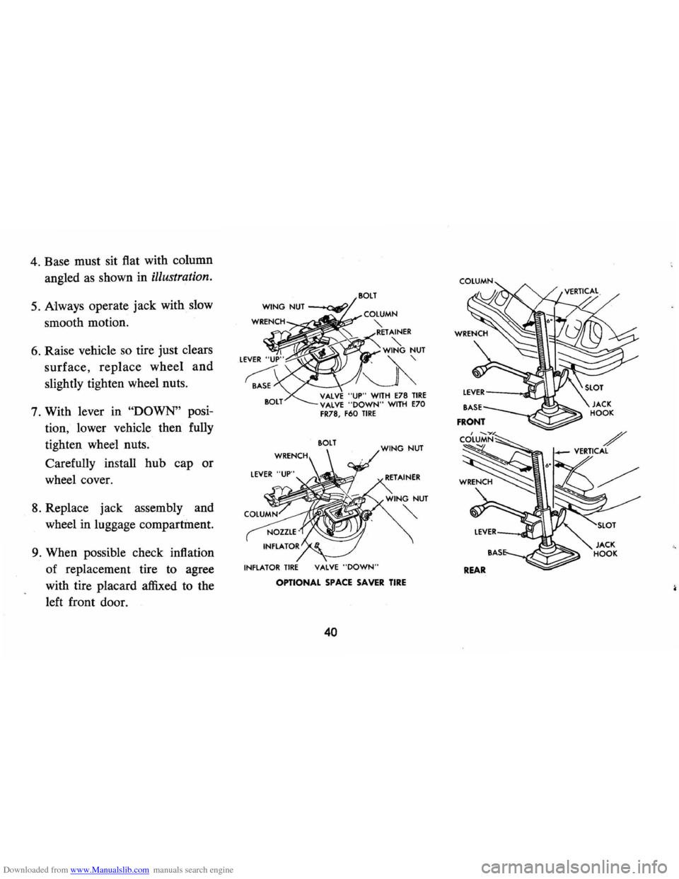
Downloaded from www.Manualslib.com manuals search engine 4. Base must sit flat with column
angled
as shown in illustration.
5. Always operate jack with slow
smooth motion.
6. Raise vehicle so tire just clears
surface,
replace wheel and
slightly tighten wheel nuts.
7. With lever in
"DOWN" posi
tion, lower vehicle then fully
tighten
wheel nuts.
Carefully install hub cap or
wheel cover.
8. Replace jack assembly and
wheel in luggage compartment.
9. When possible check inflation
of replacement tire to agree
with tire placard affixed to the
left front door.
COlUMN
;:>;;;Om~r?' ';;ErAINER
"'-WING NUT
~~
VALVE "UP" WITH E78 TIRE VALVE "DOWN" WITH E70 FR78, F60 TIRE
SOLT
INFLAT07
INFLATOR TIRE VALVE "DOWN"
OPTIONAL SPACE SAVER TIRE
40
COLUMN
JACK
HOOK