distributor CHEVROLET CAMARO 1982 Repair Guide
[x] Cancel search | Manufacturer: CHEVROLET, Model Year: 1982, Model line: CAMARO, Model: CHEVROLET CAMARO 1982Pages: 875, PDF Size: 88.64 MB
Page 640 of 875
GM – CAMARO 1982-1992 – Repair Guide (Checked by WxMax) 640
The tachometer terminal should never
be allowed to touch ground, as damage
to the computer control module and/or ignition coil assembly can result.
CONNECTORS
When disengaging connectors, do not use a screw driver or other tool to release
the locking tab, as this mi ght break the connector.
SYSTEM TESTERS
Instruments designed specific ally for testing HEI or C
3I systems are available
from several tool manufactur ers. Some of these will even test the module itself.
However, the tests given in the followin g section will require only an ohmmeter
and a voltmeter.
TESTING
The symptoms of a defective component within the HEI or C
3I system are
exactly the same as those you woul d encounter in a conventional system.
Some of these symptoms are:
• Hard or no starting
• Rough Idle
• Poor fuel economy
• Engine misses under load or while accelerating
PRELIMINARY CHECKS
If you suspect a problem in your igniti on system, there are certain preliminary
checks which you should carry out befor e you begin to check the electronic
portions of the system. First, it is extrem ely important to make sure the vehicle
battery is in a good state of charge. A defective or poorly charged battery will
cause the various components of the ignition system to read incorrectly when
they are being tested. Second, make su re all wiring connections are clean and
tight, not only at the battery, but also at the distributor cap (if so equipped),
ignition coil, camshaft and/or crankshaft sensors (if so equipped) and at the
control module.
Since the only difference between these ignition systems lies before the spark
plug wiring, it is important to check the secondary ig nition circuit first. If the
secondary circuit checks out properly (ther e is spark), then the engine condition
is probably not the fault of the ignition system. To check the secondary ignition
system, perform a simple spark test. Remove one of the plug wires and insert
some sort of extension in the plug socket. An old spark plug with the ground
electrode removed makes a good extension. Hold the wire and extension using
an insulated tool (NOT BY HAND) about
1/4 in. (6mm) away from the block and
crank the engine. If a normal spark occurs, then the problem is most likely not in
the ignition system. Check for fuel system problems, or fouled spark plugs.
Page 641 of 875
GM – CAMARO 1982-1992 – Repair Guide (Checked by WxMax) 641
If, however, there is no spark or a weak
spark, then further ignition system
testing will have to be done. Troubleshooting techniques fall into various
categories, depending on t he nature of the problem and the system being
tested. Categories will include symptom s such as the engine cranks, but will not
start or the engine runs rough.
HEI SYSTEM
When testing the HEI system, there are 2 major categories of problems, (1)
Engine cranks, but will not star t or (2) Engine runs, but runs rough or cuts out.
If the engine will not start, perform a spar k test as described earlier. This will
narrow the problem area down considerab ly. If no spark occurs, check for the
presence of normal battery voltage at the battery ( BAT) terminal on the ignition
coil. The ignition switch must be in the ON position for this test. Either a
voltmeter or a test light wire may be us ed for this test. Connect the test light
wire to ground and the probe end to the BAT terminal at the coil. If the light
comes on, you have voltage to the distribut or and/or spark plug wires. If the light
fails to come on, this indicates an open circuit in the ignition primary wiring
leading to the distributor. In this case , you will have to check wiring continuity
back to the ignition switch using a test li ght. If there is battery voltage at the BAT
terminal, but no spark at the plugs, t hen the problem probably lies within the
distributor assembly.
If, on the other hand, the engine starts, but runs roughly or cuts out, make sure
the plug wires are in good shape first. There should be no obvious cracks or
breaks. You can check the plug wires with an ohmmeter, but do not pierce the
wires with a probe. Check the chart for th e correct plug wire resistance. If the
plug wires are OK, remove the cap asse mbly and check for moisture, cracks,
chips, or carbon tracks, or any other hi gh voltage leads or failures. Replace the
cap if any defects are found. Make su re the timer wheel rotates when the
engine is cranked.
If the trouble has been narrowed down to t he units within the distributor, the
following tests can help pinpoint the defective component. An ohmmeter with
both high and low ranges shou ld be used. These tests are made with the cap
assembly removed and the battery wir e disconnected. If a tachometer is
connected to the TACH terminal, disconnect it before making these tests.
IGNITION COIL
EXTERNALLY MOUNTED 1. Disconnect the coil wires and se t the ohmmeter on the high scale.
2. Connect the ohmmeter to the ignition co il as illustrated in Step 1 of the
accompanying figure.
3. The ohmmeter should read near infinite or very high.
Page 646 of 875
GM – CAMARO 1982-1992 – Repair Guide (Checked by WxMax) 646
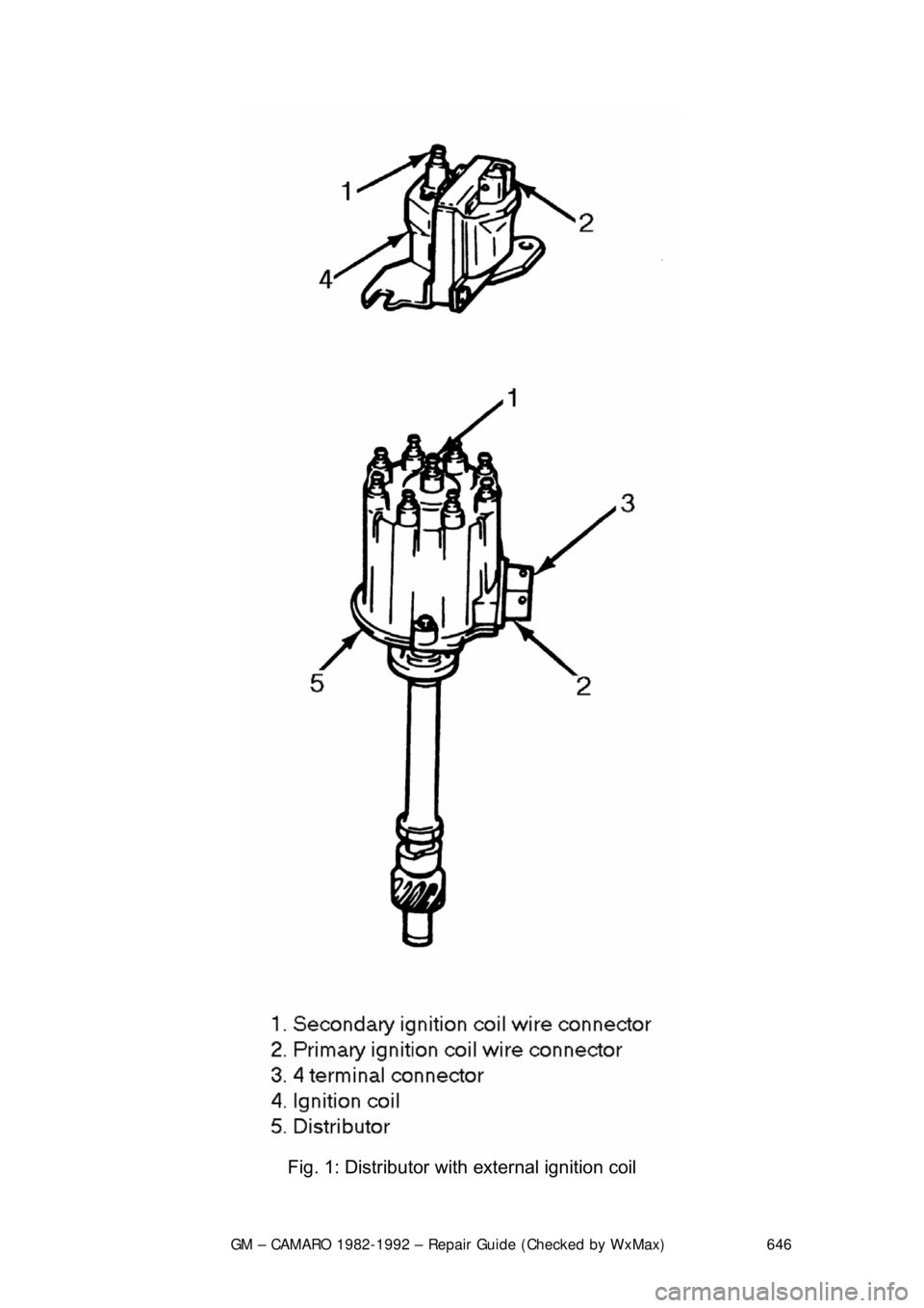
Fig. 1: Distributor with external ignition coil
Page 648 of 875
GM – CAMARO 1982-1992 – Repair Guide (Checked by WxMax) 648
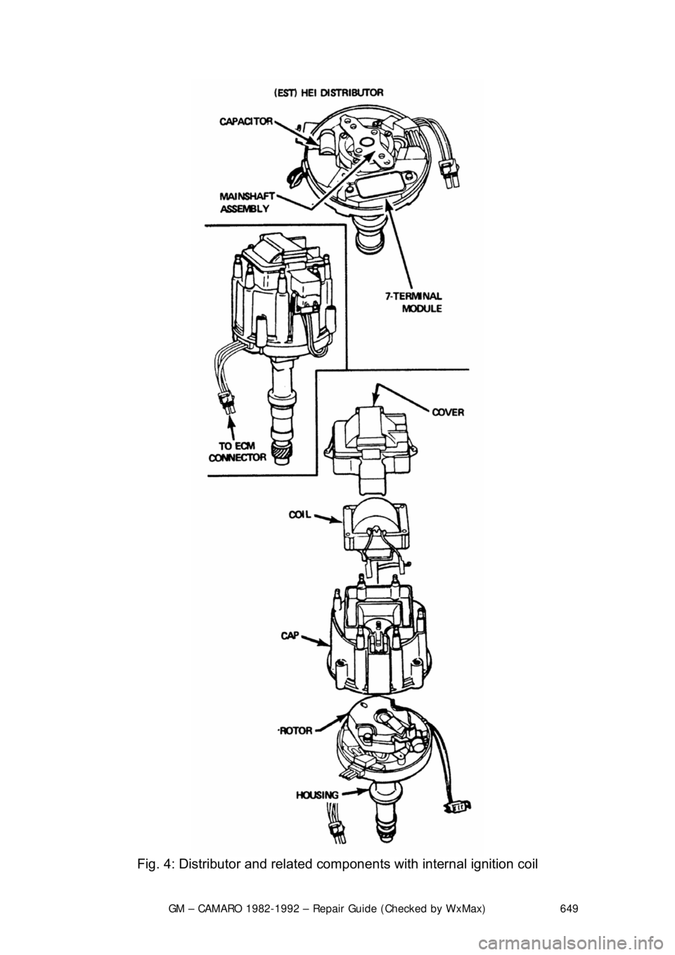
INTERNALLY MOUNTED
1. Disconnect the negative battery cable.
2. Remove the cover and wire retainer.
3. Disconnect the battery feed wire and coil connections from the cap.
4. Remove the coil cover attaching screws and cover.
5. Remove the coil attaching screws and lift the coil assembly from the
distributor cap.
To install: 6. Position the ignition coil and the leads into the cap. Be certain that the
resistor brush, ground lead and s eal are properly positioned.
7. Install the mounting screws.
8. Install the coil cove r and retainers. Reconnec t the feed wires and coil
connections to the cap.
9. Install the cover and wire retainer. Reconnect the negative battery cable.
Page 649 of 875
GM – CAMARO 1982-1992 – Repair Guide (Checked by WxMax) 649
Fig. 4: Distributor and related com ponents with internal ignition coil
Page 650 of 875
GM – CAMARO 1982-1992 – Repair Guide (Checked by WxMax) 650
DISTRIBUTOR CAP
1. If removing the ignition wires at the cap, take a moment to label the spark
plug wire positioning for each cylinder, at each tower. This will avoid
improper wire placement during assembly.
2. Disconnect the ignition switch wir e from the distributor cap. Also
disconnect the tachometer wire, if so equipped.
3. Release the coil connec tors from the cap.
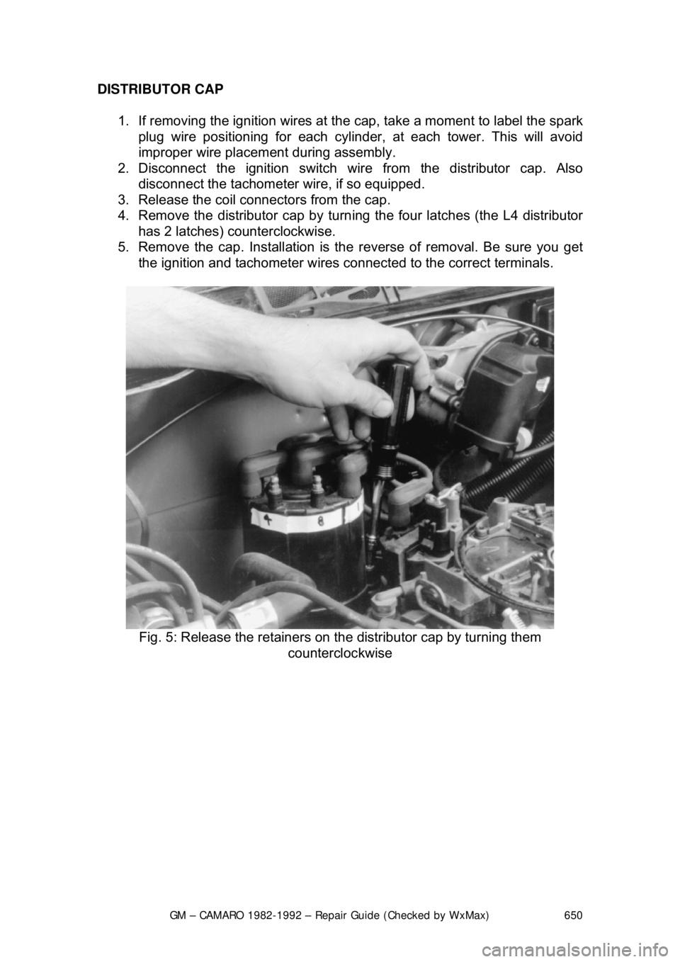
4. Remove the distributor cap by turn ing the four latches (the L4 distributor
has 2 latches) counterclockwise.
5. Remove the cap. Installation is the reverse of removal. Be sure you get
the ignition and tachometer wires c onnected to the correct terminals.
Fig. 5: Release the retainers on t he distributor cap by turning them
counterclockwise
Page 651 of 875
GM – CAMARO 1982-1992 – Repair Guide (Checked by WxMax) 651
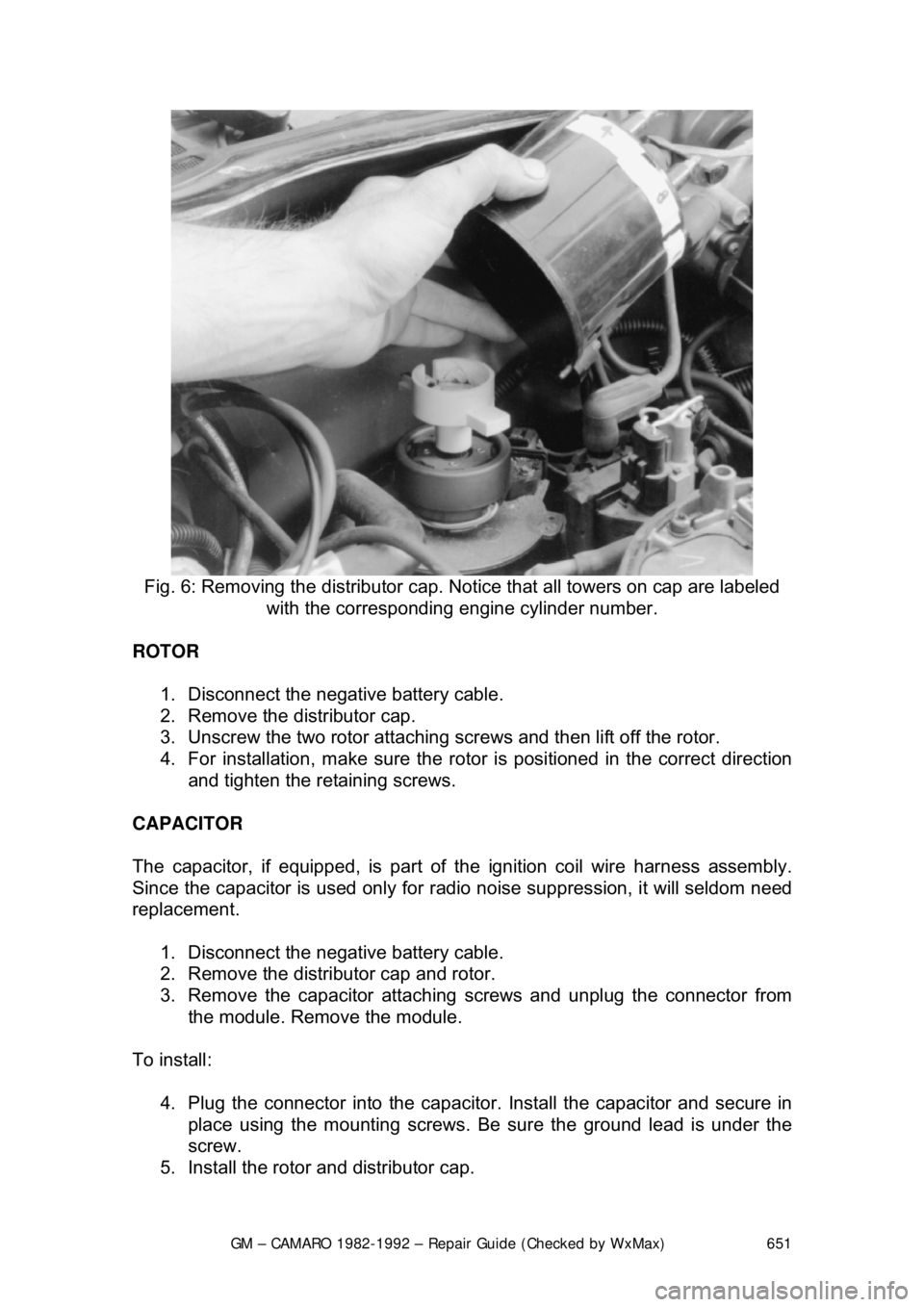
Fig. 6: Removing the distri butor cap. Notice that all towers on cap are labeled
with the corresponding engine cylinder number.
ROTOR 1. Disconnect the negative battery cable.
2. Remove the distributor cap.
3. Unscrew the two rotor attaching screws and then lift off the rotor.
4. For installation, make sure the roto r is positioned in the correct direction
and tighten the retaining screws.
CAPACITOR
The capacitor, if equipped, is part of the ignition coil wire harness assembly.
Since the capacitor is used only for radio noise suppres sion, it will seldom need
replacement.
1. Disconnect the negative battery cable.
2. Remove the distributor cap and rotor.
3. Remove the capacitor attaching screws and unplug the connector from
the module. Remove the module.
To install: 4. Plug the connector into the capacitor. Install the capacitor and secure in
place using the mounting screws. Be sure the ground lead is under the
screw.
5. Install the rotor and distributor cap.
Page 652 of 875
GM – CAMARO 1982-1992 – Repair Guide (Checked by WxMax) 652
6. Connect the negative battery cable.
MODULE
It is not necessary to remove t he distributor from the vehicle.
1. Disconnect the negative battery cable.
2. Remove the distributor cap, rotor and pickup coil.
3. Remove the 2 module attaching screws and lift the module up. Remove
the leads from the module, observi ng the colors on each lead. These
leads can not be interchanged.
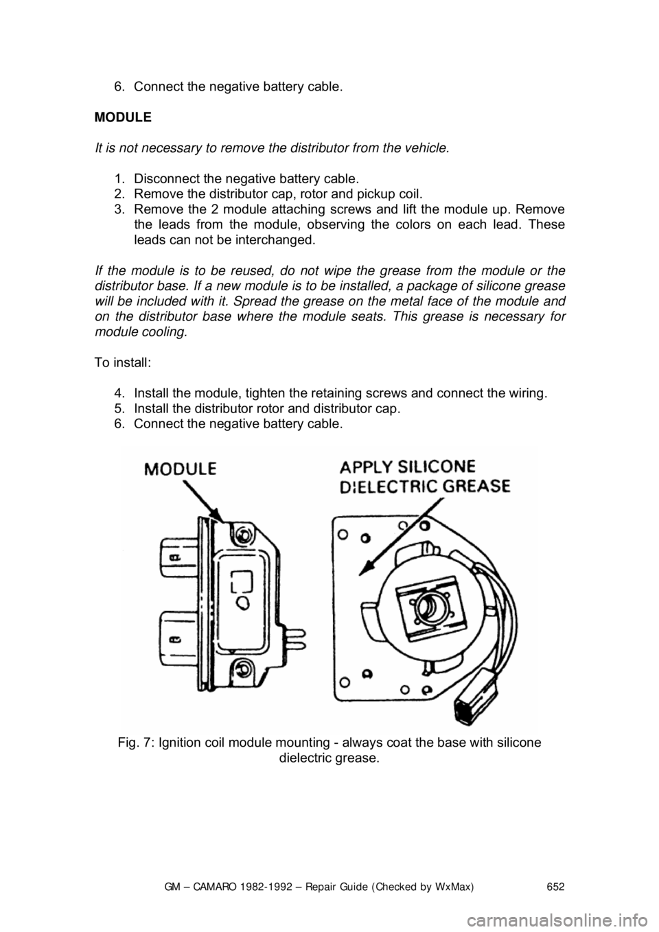
If the module is to be reused, do not wi pe the grease from the module or the
distributor base. If a new module is to be installed, a package of silicone grease
will be included with it. Spr ead the grease on the metal face of the module and
on the distributor base wher e the module seats. This grease is necessary for
module cooling.
To install: 4. Install the module, tighten the reta ining screws and connect the wiring.
5. Install the distributor rotor and distributor cap.
6. Connect the negative battery cable.
Fig. 7: Ignition coil module mounting - always coat the base with silicone
dielectric grease.
Page 653 of 875
GM – CAMARO 1982-1992 – Repair Guide (Checked by WxMax) 653
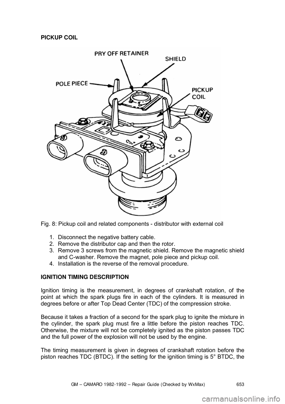
PICKUP COIL
Fig. 8: Pickup coil and related component s - distributor with external coil
1. Disconnect the negative battery cable.
2. Remove the distributor cap and then the rotor.
3. Remove 3 screws from the magnetic shield. Remove the magnetic shield
and C-washer. Remove the magnet, pole piece and pickup coil.
4. Installation is the revers e of the removal procedure.
IGNITION TIMING DESCRIPTION
Ignition timing is the measurement, in de grees of crankshaft rotation, of the
point at which the spark plugs fire in eac h of the cylinders. It is measured in
degrees before or after Top Dead Center (TDC) of the compression stroke.
Because it takes a fraction of a second for the spark plug to ignite the mixture in
the cylinder, the spark plug must fire a little before the piston reaches TDC.
Otherwise, the mixture will not be complete ly ignited as the piston passes TDC
and the full power of the explosion will not be used by the engine.
The timing measurement is given in degr ees of crankshaft rotation before the
piston reaches TDC (BTDC). If the setting fo r the ignition timing is 5° BTDC, the
Page 655 of 875
GM – CAMARO 1982-1992 – Repair Guide (Checked by WxMax) 655
2. Clean off the marks and coat them wit
h white paint or chalk, if necessary,
so that they may be seen.
3. Run the engine until it reaches no rmal operating temperature, then shut
off the engine.
4. With the ignition OFF, connect a ta chometer to the distributor, and a
timing light with an inductive pickup lead to the No. 1 spark plug wire.
WARNING - Never pierce a secondary ignition wire in order to connect a timing
light. A pierced wire may lead to engine misfiring and driveability problems.
5. To properly set the ignition timing , the EST must be placed in the bypass
mode. a. On the 2.5L engine, refer to t he emission control label for the
procedure.
If the label is missing or unreadable, c ontact your Chevrolet dealer for a
replacement.
b. On 2.8L and 5.0L ca rbureted engines, disconnect the 4-wire EST
connector at the distributor. (Fault code 42 may be set in ECM memory,
and must be cleared once the procedur e is completed). Proceed to Step
7.
c. On 2.8L, 5.0L and 5.7L fuel inje cted engines, with the engine RUNNING
and all accessories off, use a jumper wire to connect diagnostic terminal
B and ground terminal A of the 12-terminal Assembly Line Diagnostic
Link (ALDL) usually located under t he left side of the instrument panel.
DO NOT disconnect the 4-wir e EST connector at the distributor. Aim the
timing light at the timing mark; the li ne on the balancer or pulley will line
up with the timing mark. Increase engine speed and check for timing
advance. If the timing still advances with engine speed, perform Step 6. If
timing does not advance with engi ne speed, proceed to Step 7.
If timing advances with engine speed, it will be necessary to disconnect the
single-wire Set Timing connector. (Faul t code 42 may be set in ECM memory,
and must be cleared once the procedure is completed).
6. Remove the jumper wire from t he ALDL, and shut off the ignition.
Disconnect the Set Timing connector, usually located under the plastic
cover above the heater unit, in the engi ne compartment. (The wire in this
connector is normally Tan/Black.)
7. With the engine running and all accessories off, aim the light at the timing
mark. The line on the balancer or pulle y will line up with the timing mark.
If a change in timing is necessary, loosen the hold-down clamp bolt at
the base of the distributor . While observing the timing mark, rotate the
distributor slightly unt il the line indicates the correct timing. Use the
timing specification on the emi ssion control label in the engine
compartment. If this label is missi ng or damaged, refer to the Tune-Up
Specifications chart in this Section.