engine overheat CHEVROLET CAMARO 1982 Repair Guide
[x] Cancel search | Manufacturer: CHEVROLET, Model Year: 1982, Model line: CAMARO, Model: CHEVROLET CAMARO 1982Pages: 875, PDF Size: 88.64 MB
Page 135 of 875

GM – CAMARO 1982-1992 – Repair Guide (Checked by WxMax) 135
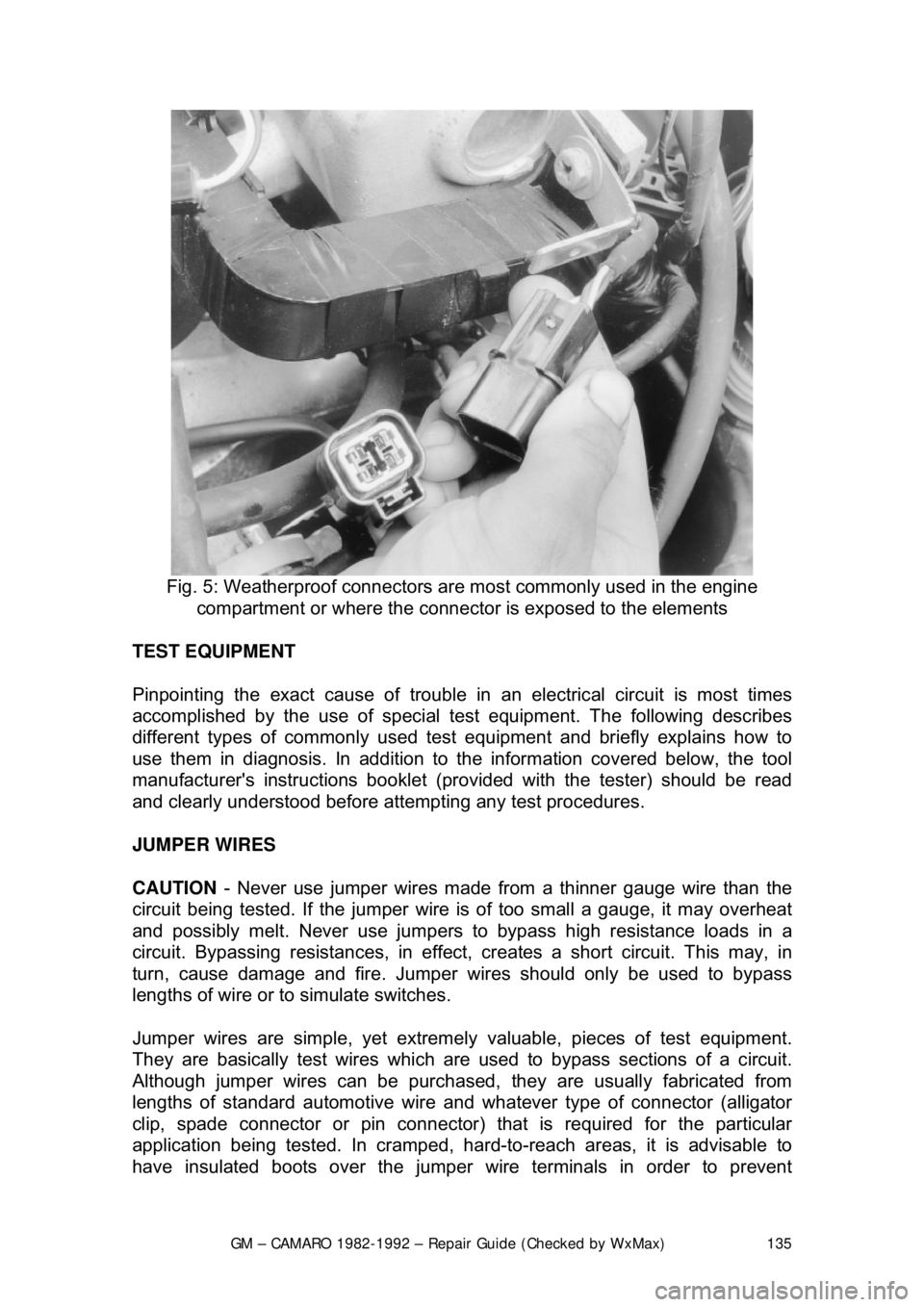
Fig. 5: Weatherproof connectors ar e most commonly used in the engine
compartment or where the connecto r is exposed to the elements
TEST EQUIPMENT
Pinpointing the exact cause of trouble in an electrical circuit is most times
accomplished by the use of special te st equipment. The following describes
different types of commonly used test eq uipment and briefly explains how to
use them in diagnosis. In addition to t he information covered below, the tool
manufacturer's instructions booklet (pro vided with the tester) should be read
and clearly understood before atte mpting any test procedures.
JUMPER WIRES
CAUTION - Never use jumper wires made from a thinner gauge wire than the
circuit being tested. If the jumper wire is of too small a gauge, it may overheat
and possibly melt. Never use jumpers to bypass high resistance loads in a
circuit. Bypassing resistances, in effect, cr eates a short circuit. This may, in
turn, cause damage and fire. Jumper wi res should only be used to bypass
lengths of wire or to simulate switches.
Jumper wires are simple, yet extremel y valuable, pieces of test equipment.
They are basically test wir es which are used to bypass sections of a circuit.
Although jumper wires can be purchased, they are usually fabricated from
lengths of standard automot ive wire and whatever type of connector (alligator
clip, spade connector or pin connector) that is required for the particular
application being tested. In cramped, hard- to-reach areas, it is advisable to
have insulated boots over the jumper wire terminals in order to prevent
Page 487 of 875

GM – CAMARO 1982-1992 – Repair Guide (Checked by WxMax) 487
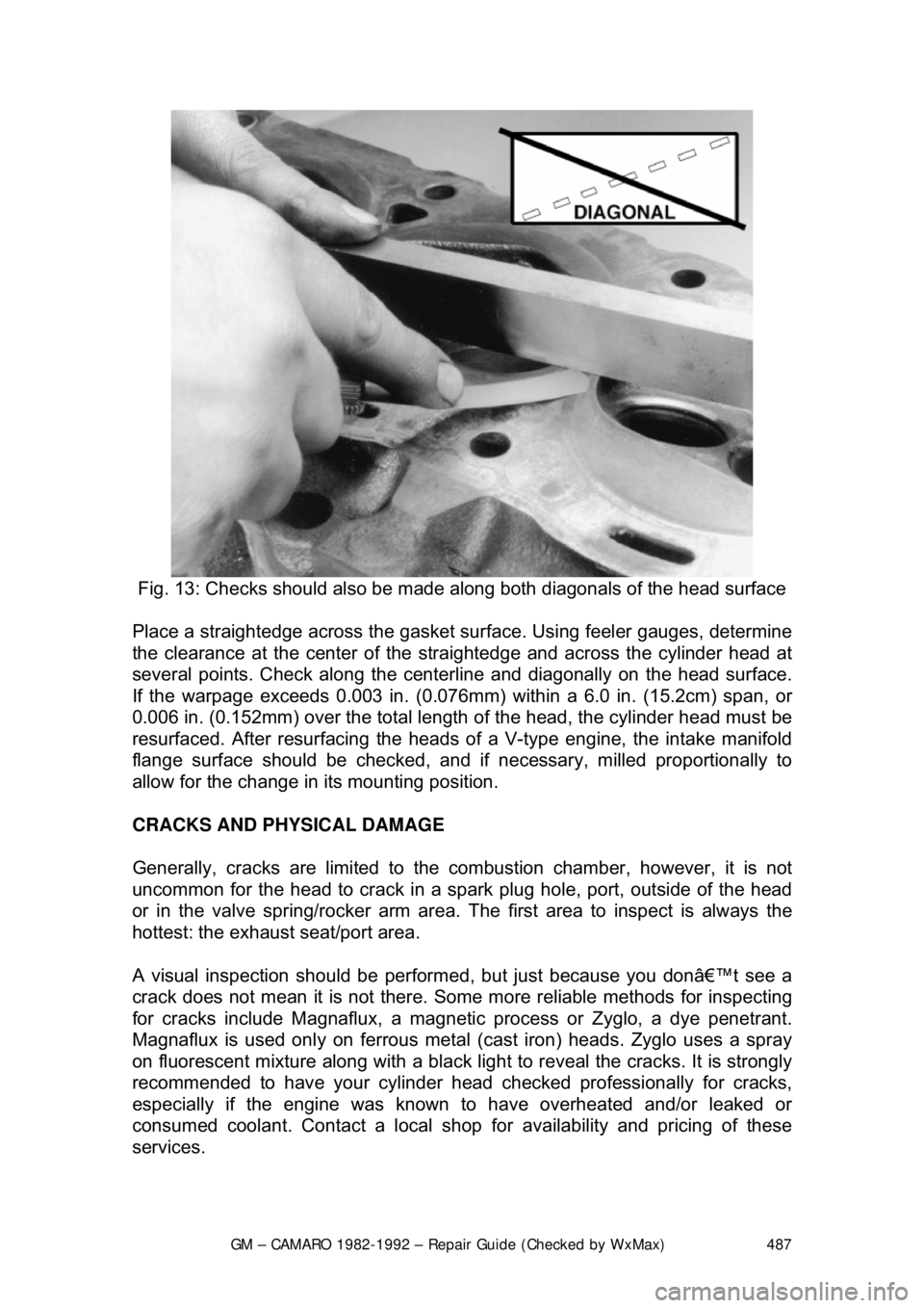
Fig. 13: Checks should also be made al ong both diagonals of the head surface
Place a straightedge across the gasket surf ace. Using feeler gauges, determine
the clearance at the cent er of the straightedge and across the cylinder head at
several points. Check along the centerli ne and diagonally on the head surface.
If the warpage exceeds 0.003 in. (0.076mm) within a 6.0 in. (15.2cm) span, or
0.006 in. (0.152mm) over the total length of the head, the cylinder head must be
resurfaced. After resurfacing the heads of a V-type engine, the intake manifold
flange surface should be checked, and if necessary, milled proportionally to
allow for the change in its mounting position.
CRACKS AND PHYSICAL DAMAGE
Generally, cracks are limited to the comb ustion chamber, however, it is not
uncommon for the head to crack in a s park plug hole, port, outside of the head
or in the valve spring/rocker arm area. The first area to inspect is always the
hottest: the exhaust seat/port area.
A visual inspection should be perform ed, but just because you don’t see a
crack does not mean it is not there. Some more reliable methods for inspecting
for cracks include Magnaflux, a magnetic process or Zyglo, a dye penetrant.
Magnaflux is used onl y on ferrous metal (cast iron) heads. Zyglo uses a spray
on fluorescent mixture along with a black light to reveal the cracks. It is strongly
recommended to have your cylinder head c hecked professionally for cracks,
especially if the engine was known to have overheated and/or leaked or
consumed coolant. Contact a local shop fo r availability and pricing of these
services.
Page 495 of 875

GM – CAMARO 1982-1992 – Repair Guide (Checked by WxMax) 495
Again, rotate the engine, this time
to position the number one cylinder bore
(head surface) up. Turn the crankshaft until the number one piston is at the
bottom of its travel, this should allow t he maximum access to its connecting rod.
Remove the number one co nnecting rods fasteners and cap and place two
lengths of rubber hose over the rod bolts/studs to protect the crankshaft from
damage. Using a sturdy wooden dowel and a hammer, push the connecting rod
up about 1 in. (25mm) from the cranks haft and remove the upper bearing insert.
Continue pushing or tapping the connecti ng rod up until the piston rings are out
of the cylinder bore. Remove the piston and rod by hand, put the upper half of
the bearing insert back into the rod, in stall the cap with its bearing insert
installed, and hand-tighten the cap fasteners. If the parts are kept in order in this
manner, they will not get lost and you wil l be able to tell which bearings came
form what cylinder if any problems are discovered and diagnosis is necessary.
Remove all the other piston assemblie s in the same manner. On V-style
engines, remove all of the pistons from one bank, then reposition the engine
with the other cylinder bank head surface up, and remo ve that banks piston
assemblies.
The only remaining component in the engine block should now be the
crankshaft. Loosen the main bearing ca ps evenly until the fasteners can be
turned by hand, then remove them and the caps. Remove the crankshaft fro\
m
the engine block. Thoroughly clea n all of the components.
INSPECTION
Now that the engine block and all of its components ar e clean, it's time to
inspect them for wear and/or damage. To accurately inspect them, you will need
some specialized tools:
• Two or three separate micromet ers to measure the pistons and
crankshaft journals
• A dial indicator
• Telescoping gauges for the cylinder bores
• A rod alignment fixture to check for bent connecting rods
If you do not have access to the proper tools, you may want to bring the
components to a shop that does.
Generally, you shouldn't expect cracks in the engine block or its components
unless it was known to leak, consume or mix engine fluids, it was severely
overheated, or there was ev idence of bad bearings and/or crankshaft damage.
A visual inspection should be performed on all of the components, but just
because you don't see a crack does not mean it is not there. Some more
reliable methods for inspecting for cracks include Magnaflux, a magnetic
process or Zyglo, a dye penetrant. M agnaflux is used only on ferrous metal
(cast iron). Zyglo uses a spray on fluoresce nt mixture along with a black light to
reveal the cracks. It is strongly recommended to have your engine block
checked professionally for cracks, especia lly if the engine was known to have
overheated and/or leaked or consumed coolant. Contact a local shop for
availability and pricing of these services.
Page 547 of 875

GM – CAMARO 1982-1992 – Repair Guide (Checked by WxMax) 547
EXHAUST GAS RECIRCULATION (EGR) SYSTEM
OPERATION
All models are equipped with
this system, which consists of a metering valve, a
vacuum line to the carburet or or intake manifold, and cast-in exhaust passages
in the intake manifold. The EGR valve is controlled by vacuum, which opens
and closes in response to the vacuum signals to admit exhaust gases into the
air/fuel mixture. The exhaust gases lower peak combustion temperatures,
reducing the formation of NOx. The valve is closed at idle and wide open
throttle, but is open between the two extreme positions.
There are actually four types of EGR systems: Ported, Positive Back-Pressure,
Negative Backpressure and Digital. The pr inciple of all the systems are the
same; the only difference is in the me thod used to control how the EGR valve
opens.
Too much EGR flow at idle, cruise or during cold operation may result in the
engine stalling after cold start, the engine stalling at idle after deceleration,
vehicle surge during cruise and rough idle . If the EGR valve is always open, the
vehicle may not idle. Too little or no EGR flow allows combustion temperatures
to rise, which could result in spar k knock (detonation), engine overheating
and/or emission test failure.
A Thermal Vacuum Switch (TVS) or vacuum control solenoid may sometimes\
be used in combination with the EGR va lve. The TVS will close off vacuum
during cold operation. A va cuum control solenoid uses Pulse Width Modulation
(PWM) to turn the solenoid ON and OFF numerous times a second and varies
the amount of ON time (pulse width) to vary the amount of ported vacuum
supplied the EGR valve.
PORTED VALVE
In the ported system, the amount of ex haust gas admitted into the intake
manifold depends on a ported vacuum signal. A ported vacuum signal is one
taken from the carburetor above the th rottle plates; thus, the vacuum signal
(amount of vacuum) is dependent on how far the throttle plates are opened.
When the throttle is closed (idle or dec eleration) there is no vacuum signal.
Thus, the EGR valve is closed, and no exhaust gas enters the intake mani\
fold.
As the throttle is opened, a vacuum is produced, which opens the EGR valve,
admitting exhaust gas into the intake manifold.
POSITIVE BACKPRE SSURE VALVE
This valve operates the same as the ported, except, it has an internal air bleed
that acts as a vacuum regulator. T he bleed valve controls the amount of
vacuum inside the vacuum chamber duri ng operation. When the valve receives
sufficient exhaust backpressure through the hollow shaft, it closes the bleed; at
this point the EGR valve opens.
Page 559 of 875

GM – CAMARO 1982-1992 – Repair Guide (Checked by WxMax) 559
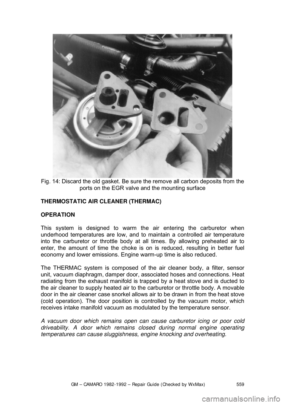
Fig. 14: Discard the old gasket. Be sure the remove all carbon deposits from the
ports on the EGR valve and the mounting surface
THERMOSTATIC AIR CLEANER (THERMAC)
OPERATION
This system is designed to warm the air entering the carburetor when
underhood temperatures are low, and to ma intain a controlled air temperature
into the carburetor or throttle body at all times. By allowing preheated air to
enter, the amount of time t he choke is on is reduced, resulting in better fuel
economy and lower emissions. Engine warm-up time is also reduced.
The THERMAC system is composed of th e air cleaner body, a filter, sensor
unit, vacuum diaphragm, damper door, a ssociated hoses and connections. Heat
radiating from the exhaust manifold is tr apped by a heat stove and is ducted to
the air cleaner to supply heated air to t he carburetor or throttle body. A movable
door in the air cleaner case snorkel allows air to be drawn in from the heat stove
(cold operation). The door position is co ntrolled by the vacuum motor, which
receives intake manifold vacuum as modulated by the temperature sensor.
A vacuum door which remain s open can cause carburetor icing or poor cold
driveability. A door which remains clos ed during normal engine operating
temperatures can cause sluggishne ss, engine knocking and overheating.
Page 795 of 875

GM – CAMARO 1982-1992 – Repair Guide (Checked by WxMax) 795
Fill the cooling system wit
h a 50/50 mixture of water and Ethylene Glycol
antifreeze. Freezing protection should be appropriate for temperatures of -34°F
(-37°C). When filling the coolant system, add two cooling system sealer pellets
(GM part no. 3634621 or equivalent).
9. Firmly set the parking brake. Run t he engine with the radiator cap OFF,
until normal operating tem perature is reached.
CAUTION - Under some conditions, ethylene glycol is flammable. To avoid
being burned when adding engine coolant, do not spill it on the exhaust system
or on hot engine parts.
10. With the engine idlin g, add engine coolant to t he radiator until the level
reaches the bottom of t he radiator fill neck. Install the cap assembly.
When installing the cap, make sure t hat the arrows on the cap line up
with the overflow tube.
Never add cold water to an overheated engine.
11. Add coolant to the recovery tank, as necessary.
12. After filling the radiator and recovery tank, run the engine until it reaches
normal operating temperature, to ma ke sure that the thermostat has
opened and all the air is bled from the system.
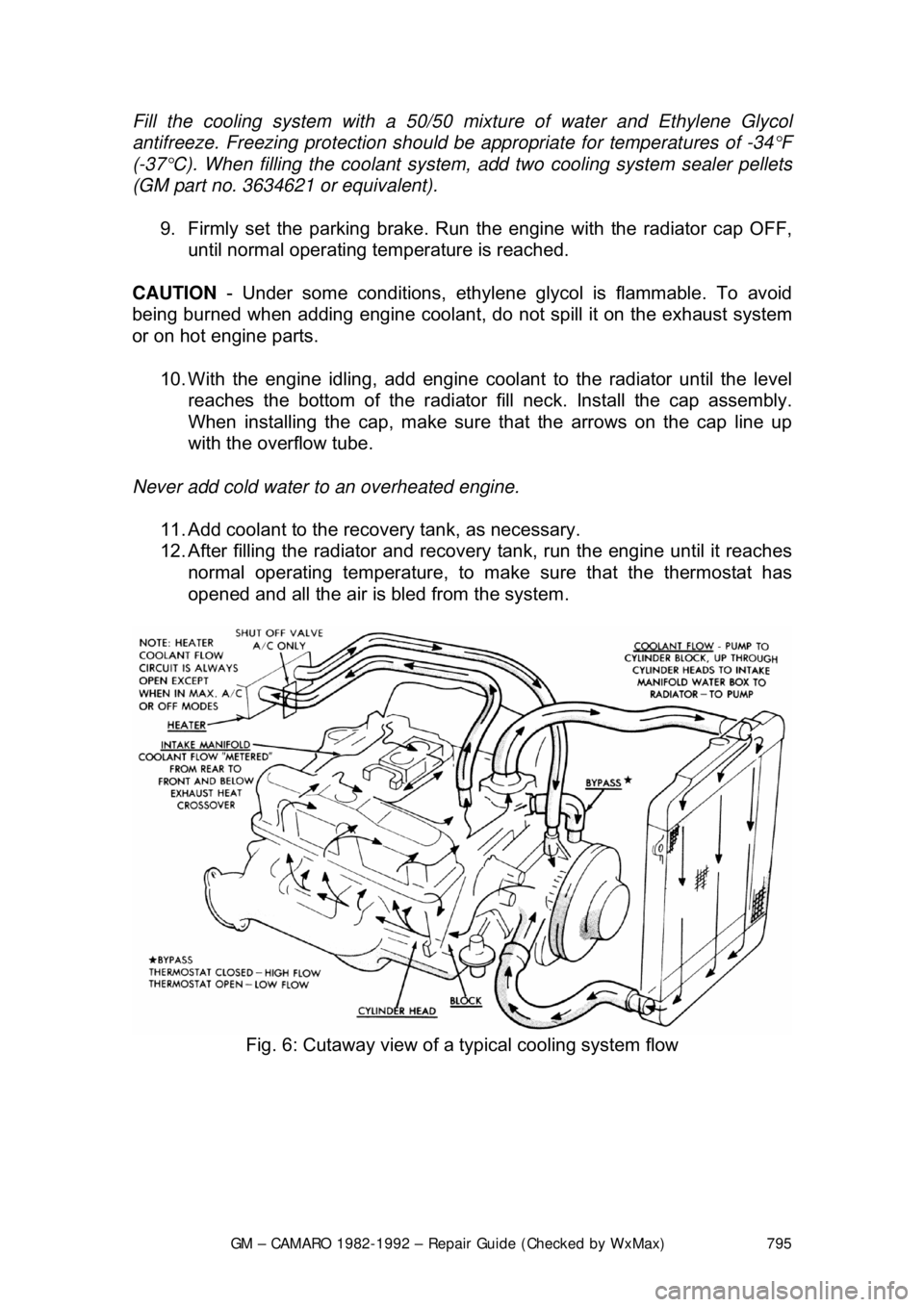
Fig. 6: Cutaway view of a typical cooling system flow