heating CHEVROLET CAMARO 1982 Repair Guide
[x] Cancel search | Manufacturer: CHEVROLET, Model Year: 1982, Model line: CAMARO, Model: CHEVROLET CAMARO 1982Pages: 875, PDF Size: 88.64 MB
Page 151 of 875

GM – CAMARO 1982-1992 – Repair Guide (Checked by WxMax) 151
ARMING THE SYSTEM
1. Turn the ignition key to the LO CK position and remove the key.
2. On vehicles with a passenger side ai r bag, reconnect the yellow two-way
connector assembly located near the yellow 24-way DERM harness
connector. Install the glov e box door assembly.
3. Connect the yellow two-way connector assembly at the base of the
steering column.
Always be sure to reinstall the Connec tor Position Assurance (CPA) device.
4. Install the left side trim panel and rein stall the fuse in the fuse block.
5. Turn the ignition key to the RUN posit ion and verify that the warning lamp
flashes seven to nine times and then turn s OFF. If it does not operate as
described, have the system repair ed by a qualified technician.
HEATING AND AIR CONDITIONING
BLOWER MOTOR
REMOVAL & INSTALLATION 1. Disconnect the negative battery cable. If necessary, remove the diagonal
fender brace at the right rear corner of the engine compartment to gain
access to the blower motor.
2. Disconnect the electrical wiring fr om the blower motor. If equipped with
air conditioning, remove the blower relay and bracket as an assembly
and swing them aside.
3. Remove the blower motor cooling tube.
4. Remove the blower mo tor retaining screws.
5. Remove the blower motor and fan as an assembly from the case.
To install: 6. Position the blower motor into pl ace and install the retaining screws.
7. Install the blower motor cooling tube.
8. Connect all the electrical connections.
9. Connect the negative battery cable.
Page 167 of 875

GM – CAMARO 1982-1992 – Repair Guide (Checked by WxMax) 167
BLOWER SWITCH
With the control head removed from t
he vehicle, the blower switch may be
removed by pulling the blower switch knob off and removing the retaining clip or
retaining screws.
VACUUM MOTORS
OPERATION
Used on certain heating and air condition ing systems, the vacuum actuators
operate the air doors determining the differ ent modes. The actuator consists of
a spring loaded diaphragm connec ted to a lever. When vacuum is applied to the
diaphragm, the lever moves t he control door to its appropriate position. When
the lever on the control panel is moved to another position, vacuum is cut off
and the spring returns the actuator lever to its normal position.
TESTING 1. Disconnect the vacuum line from the actuator.
2. Attach a hand held vacuum pump to the actuator.
3. Apply vacuum to the actuator.
4. The actuator lever should move to its engaged position and remain there
while vacuum is applied.
5. When vacuum is released it should move back to its normal position.
6. The lever should operat e smoothly and not bind.
REMOVAL & INSTALLATION 1. Remove the vacuum li nes from the actuator.
2. Disconnect the linkage from the actuator.
3. Remove the hardware attaching the actuator.
4. Remove the actuator.
To install: 5. Install the actuator and attaching hardware.
6. Connect the linkage to the actuator.
7. Connect the vacuum lines to the actuator.
8. Test system to confirm proper functioning of the actuator.
Page 547 of 875

GM – CAMARO 1982-1992 – Repair Guide (Checked by WxMax) 547
EXHAUST GAS RECIRCULATION (EGR) SYSTEM
OPERATION
All models are equipped with
this system, which consists of a metering valve, a
vacuum line to the carburet or or intake manifold, and cast-in exhaust passages
in the intake manifold. The EGR valve is controlled by vacuum, which opens
and closes in response to the vacuum signals to admit exhaust gases into the
air/fuel mixture. The exhaust gases lower peak combustion temperatures,
reducing the formation of NOx. The valve is closed at idle and wide open
throttle, but is open between the two extreme positions.
There are actually four types of EGR systems: Ported, Positive Back-Pressure,
Negative Backpressure and Digital. The pr inciple of all the systems are the
same; the only difference is in the me thod used to control how the EGR valve
opens.
Too much EGR flow at idle, cruise or during cold operation may result in the
engine stalling after cold start, the engine stalling at idle after deceleration,
vehicle surge during cruise and rough idle . If the EGR valve is always open, the
vehicle may not idle. Too little or no EGR flow allows combustion temperatures
to rise, which could result in spar k knock (detonation), engine overheating
and/or emission test failure.
A Thermal Vacuum Switch (TVS) or vacuum control solenoid may sometimes\
be used in combination with the EGR va lve. The TVS will close off vacuum
during cold operation. A va cuum control solenoid uses Pulse Width Modulation
(PWM) to turn the solenoid ON and OFF numerous times a second and varies
the amount of ON time (pulse width) to vary the amount of ported vacuum
supplied the EGR valve.
PORTED VALVE
In the ported system, the amount of ex haust gas admitted into the intake
manifold depends on a ported vacuum signal. A ported vacuum signal is one
taken from the carburetor above the th rottle plates; thus, the vacuum signal
(amount of vacuum) is dependent on how far the throttle plates are opened.
When the throttle is closed (idle or dec eleration) there is no vacuum signal.
Thus, the EGR valve is closed, and no exhaust gas enters the intake mani\
fold.
As the throttle is opened, a vacuum is produced, which opens the EGR valve,
admitting exhaust gas into the intake manifold.
POSITIVE BACKPRE SSURE VALVE
This valve operates the same as the ported, except, it has an internal air bleed
that acts as a vacuum regulator. T he bleed valve controls the amount of
vacuum inside the vacuum chamber duri ng operation. When the valve receives
sufficient exhaust backpressure through the hollow shaft, it closes the bleed; at
this point the EGR valve opens.
Page 559 of 875

GM – CAMARO 1982-1992 – Repair Guide (Checked by WxMax) 559
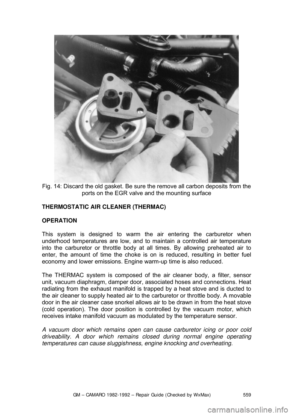
Fig. 14: Discard the old gasket. Be sure the remove all carbon deposits from the
ports on the EGR valve and the mounting surface
THERMOSTATIC AIR CLEANER (THERMAC)
OPERATION
This system is designed to warm the air entering the carburetor when
underhood temperatures are low, and to ma intain a controlled air temperature
into the carburetor or throttle body at all times. By allowing preheated air to
enter, the amount of time t he choke is on is reduced, resulting in better fuel
economy and lower emissions. Engine warm-up time is also reduced.
The THERMAC system is composed of th e air cleaner body, a filter, sensor
unit, vacuum diaphragm, damper door, a ssociated hoses and connections. Heat
radiating from the exhaust manifold is tr apped by a heat stove and is ducted to
the air cleaner to supply heated air to t he carburetor or throttle body. A movable
door in the air cleaner case snorkel allows air to be drawn in from the heat stove
(cold operation). The door position is co ntrolled by the vacuum motor, which
receives intake manifold vacuum as modulated by the temperature sensor.
A vacuum door which remain s open can cause carburetor icing or poor cold
driveability. A door which remains clos ed during normal engine operating
temperatures can cause sluggishne ss, engine knocking and overheating.
Page 784 of 875

GM – CAMARO 1982-1992 – Repair Guide (Checked by WxMax) 784
b. If fluid is warm, the le
vel should be close to the ADD mark, either
above or below.
c. If fluid is too hot to touc h, the level should be at the FULL mark.
3. If the fluid level is low, add Dexr on®II automatic transmission fluid (ATF)
through the dipstick tube. This is eas ily done with the aid of a funnel.
Check the level often as you are f illing the transmission. Be extremely
careful not to overfill it. Overfilling will cause slippage, seal damage and
overheating. Approximately 1 pint (0.473L) of ATF will raise the fluid level
from one notch/line to the other.
If the fluid on the dipstick appears discolored (brown or black), or smells burnt,
serious transmission troubles, probably due to overheating, should be
suspected. The transmission should be inspected by a qualified technician to
locate the cause of the burnt fluid.
DRAIN AND REFILL
Please refer to the "PAN AND FILTER SERVICE" procedure listed in this
section.
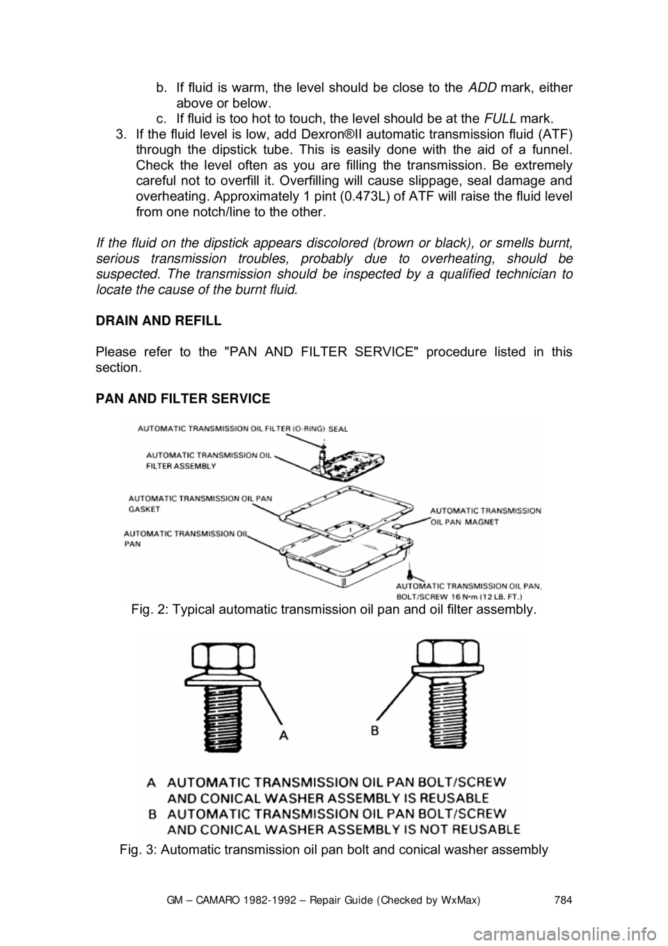
PAN AND FILTER SERVICE
Fig. 2: Typical automatic transmiss ion oil pan and oil filter assembly.
Fig. 3: Automatic transmission oil pan bolt and conical washer assembly