tires CHEVROLET CAMARO 1982 Repair Guide
[x] Cancel search | Manufacturer: CHEVROLET, Model Year: 1982, Model line: CAMARO, Model: CHEVROLET CAMARO 1982Pages: 875, PDF Size: 88.64 MB
Page 75 of 875

GM – CAMARO 1982-1992 – Repair Guide (Checked by WxMax) 75
5. Have your assistant sl
owly depress the brake pedal. As this is done, open
the bleeder screw 3/4 of a turn and allow the flui d to run through the tube.
Then close the bleeder screw before the pedal reaches the end of its travel.
Have your assistant slo wly release the pedal. Rep eat this process until no
air bubbles appear in the expelled fluid.
6. Repeat the procedure on the other three br akes, checking the level of fluid in
the master cylinder reservoir often.
7. Upon completion, check the brak e pedal for sponginess and the brake
warning light for unbalanced pressure . If necessary, repeat the entire
bleeding procedure.
FRONT DISC BRAKES
CAUTION - Some brake pads contain asbest os, which has been determined to
be a cancer causing agent. Never clean the brake surfaces with compressed
air! Avoid inhaling any dust from any brake surface! When cleaning brake
surfaces, use a commercially available brake cleaning fluid.
BRAKE PADS
CAUTION - Some brake pads contain asbest os, which has been determined to
be a cancer causing agent. Never clean the brake surfaces with compressed
air! Avoid inhaling any dust from any brake surface! When cleaning brake
surfaces, use a commercially available brake cleaning fluid.
INSPECTION
The pad thickness should be inspected ever y time that the tires are removed for
rotation. The outer pad can be checked by looking in each end, which is the
point at which the highest rate of wear occurs. The inner pad can be checked by
looking down through the inspection hole in the top of the caliper. If the
thickness of the pad is worn to within 0.030 in. (0.8mm) of the rivet at either end
of the pad, all the pads should be replaced.
Always replace all pads on both front wheel s at the same time. Failure to do so
will result in uneven braking action and premature wear.
REMOVAL & INSTALLATION
Page 122 of 875

GM – CAMARO 1982-1992 – Repair Guide (Checked by WxMax) 122
REAR DISC BRAKES
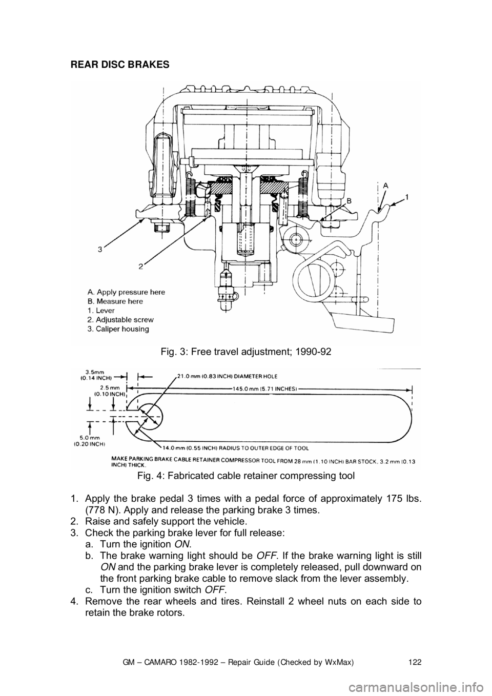
Fig. 3: Free trav el adjustment; 1990-92
Fig. 4: Fabricated cable retainer compressing tool
1. Apply the brake pedal 3 times with a pedal force of approximately 175 lbs.
(778 N). Apply and release t he parking brake 3 times.
2. Raise and safely support the vehicle.
3. Check the parking brake lever for full release: a. Turn the ignition ON.
b. The brake warning light should be OFF. If the brake warning light is still
ON and the parking brake lever is comple tely released, pull downward on
the front parking brake cable to remove slack from the lever assembly.
c. Turn the ignition switch OFF.
4. Remove the rear wheels and tires. Reinstall 2 wheel nuts on each side to
retain the brake rotors.
Page 337 of 875

GM – CAMARO 1982-1992 – Repair Guide (Checked by WxMax) 337
7. Use a suitable tool to remove the pinion seal.
To install: 8. Inspect the sealing surfaces of the pinion yoke for nicks or damage and
replace, as necessary. Examine the carrier bore and remove any burrs
that may cause leaks around the outside of the seal.
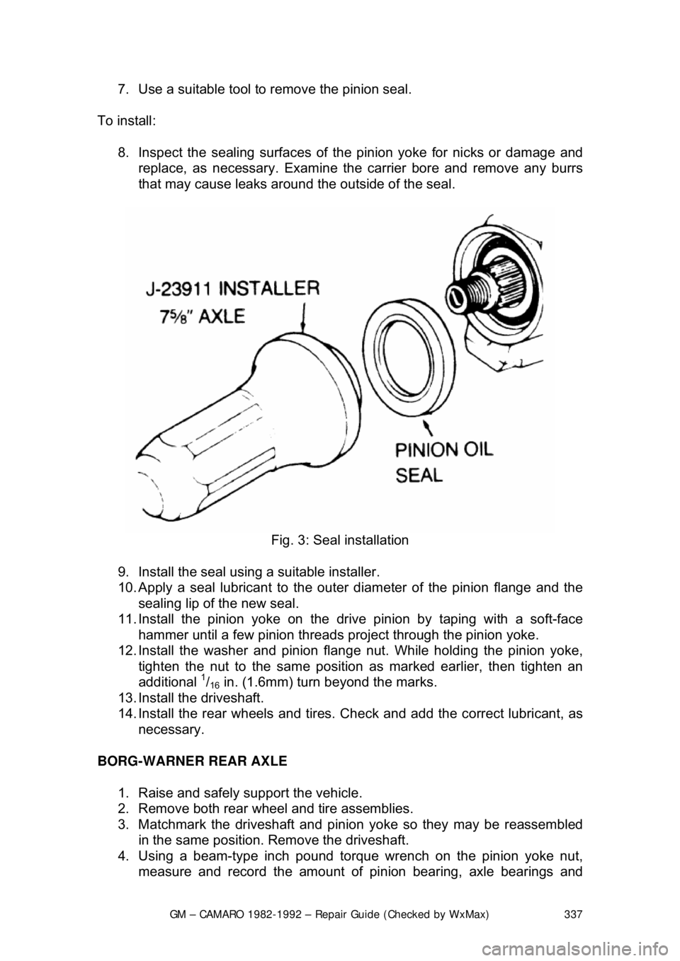
Fig. 3: Seal installation
9. Install the seal using a suitable installer.
10. Apply a seal lubricant to the outer diameter of the pinion flange and the
sealing lip of the new seal.
11. Install the pinion yoke on the drive pinion by taping with a soft-face
hammer until a few pinion threads project through the pinion yoke.
12. Install the washer an d pinion flange nut. While hol ding the pinion yoke,
tighten the nut to the same positi on as marked earlier, then tighten an
additional
1/16 in. (1.6mm) turn beyond the marks.
13. Install the driveshaft.
14. Install the rear wheels and tires. Check and add the correct lubricant, as
necessary.
BORG-WARNER REAR AXLE 1. Raise and safely support the vehicle.
2. Remove both rear wheel and tire assemblies.
3. Matchmark the driveshaft and pinion yoke so they may be reassembled
in the same position. Remove the driveshaft.
4. Using a beam-type inch pound to rque wrench on the pinion yoke nut,
measure and record the amount of pi nion bearing, axle bearings and
Page 338 of 875

GM – CAMARO 1982-1992 – Repair Guide (Checked by WxMax) 338
seal preload. Turn the torque wrenc
h smoothly for several rotations and
record the amount of preload as the a ssembly is turning, not the initial
force required to start the assembly moving.
Preload is measured as the amount of torque required to turn the assembly.
5. Using a suitable tool to hold the pi nion yoke in place, remove the pinion
yoke nut and washer.
6. Place a suitable contai ner under the differential to catch any fluid that
may drain from the rear axle. Using a suitable tool, remove the pinion
flange.
7. Use a suitable tool to remove the pinion seal.
To install: 8. Inspect the seal surface of the pinion flange for tool marks, nicks or
damage and replace, as necessary. Examine the carrier bore and
remove any burrs that might cause leaks around the outside of the seal.
9. Install the seal 0.010 in. (0.2 5mm) below the flange surface using a
suitable seal installer.
10. Apply suitable seal lubricant to t he outer diameter of the pinion flange
and the sealing lip of the new seal.
11. Install the pinion flan ge on the drive pinion by taping with a soft hammer
until a few pinion threads projec t through the pinion flange.
12. Install the washer and pinion fla nge nut. While holding the pinion flange,
tighten the nut a little at a time and turn the drive pinion several
revolutions after each tightening, to set the bearing rollers. Check the
preload each time with a suitable inch pound to rque wrench until the
preload is 5 inch lbs. (0.6 Nm) more then the reading obtained during
disassembly.
13. Install the driveshaft.
14. Install the rear wheels and tires. Check and add the correct lubricant, as
necessary.
AXLE HOUSING
REMOVAL & INSTALLATION 1. Raise the vehicle and support it sa fely. Be sure that the rear axle
assembly is supported safely.
2. Disconnect shock absorbers from ax le. Remove the wheel assemblies.
3. Mark driveshaft and pinion flange, then disconnect driveshaft and support out of the way.
4. Remove brake line junction block bolt at axle housing. If necessary,
disconnect the brake lines at the junction block.
Page 817 of 875

GM – CAMARO 1982-1992 – Repair Guide (Checked by WxMax) 817
SUSPENSION & STEERING
SUSPENSION AND STEERING WHEELS
REMOVAL & INSTALLATION
• Park the vehicle on a level surface.
• Remove the jack, tire iron and, if nec essary, the spare tire from their
storage compartments.
• Check the owner's manual or refer to General Information & Maintenance
of this repair guide for the jacking poi nts on your vehicle. Then, place the
jack in the proper position.
• If equipped with lug nut trim caps, remo ve them by either unscrewing or
pulling them off the lug nuts, as appr opriate. Consult the owner's manual,
if necessary.
• If equipped with a wheel cover or hub c ap, insert the tapered end of the
tire iron in the groove and pry off the cover.
1. Apply the parking brake and block the diagonally opposite wheel with a
wheel chock or two.
Wheel chocks may be purchased at your lo cal auto parts store, or a block of
wood cut into wedges may be used. If possi ble, keep one or two of the chocks
in your tire storage compartment, in case any of the tires has to be removed on
the side of the road.
2. If equipped with an automatic transmi ssion, place the selector lever in P
or Park; with a manual transmission, place the shifter in Reverse.
3. With the tires still on the ground, use the tire iron/wrench to break the lug
nuts loose.
If a nut is stuck, never use heat to loosen it or damage to the wheel and
bearings may occur. If the nuts are seized, one or two heavy hammer blows
directly on the end of the bol t usually loosens the rust. Be careful, as continued
pounding will likely damage the brake drum or rotor.
3. Using the jack, raise the vehicle unt il the tire is clear of the ground.
Support the vehicle safely using jackstands.
4. Remove the lug nuts, then remove the tire and wheel assembly.
To install:
5. Make sure the wheel and hub mating su rfaces, as well as the wheel lug
studs, are clean and free of all foreign material. Always remove rust from
the wheel mounting surfac e and the brake rotor or drum. Failure to do so
may cause the lug nuts to loosen in service.
6. Install the tire and wheel asse mbly and hand-tighten the lug nuts.
7. Using the tire wrench, tighten all the lug nuts, in a crisscross pattern, until
they are snug.
8. Raise the vehicle and withdraw the jackstand, then lower the vehicle.
Page 819 of 875

GM – CAMARO 1982-1992 – Repair Guide (Checked by WxMax) 819
INSPECTION
Inspect the tires for lacerations, puncture
marks, nails and other sharp objects.
Repair or replace as necessary. Also check the tires for treadwear and air
pressure as outlined in General Information & Maintenance of this repair guide.
Check the wheel assemblies for dents, crac ks, rust and metal fatigue. Repair or
replace as necessary.
WHEEL LUG STUDS
REMOVAL & INSTALLATION
WITH DISC BRAKES
1. Raise and support the appropriate end of the vehicle safely using
jackstands, then remove the wheel.
2. Remove the brake pads and caliper. Support the caliper aside using wire
or a coat hanger. For details, please re fer to Brakes of this repair guide.
3. Remove the outer w heel bearing and lift off the rotor. For details on
wheel bearing removal, installation and adjustment, please refer to
General Information & Maintenan ce of this repair guide.
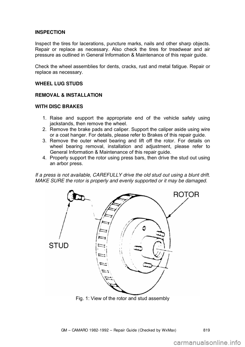
4. Properly support the rotor using pre ss bars, then drive the stud out using
an arbor press.
If a press is not available, CAREFULLY drive the old stud out using a blunt drift.
MAKE SURE the rotor is properly and ev enly supported or it may be damaged.
Fig. 1: View of the rotor and stud assembly